Tightening torques for gazelle threaded connections
Attention! Experienced mechanics advise choosing the middle range from the data below. Since all torque wrenches have a small error.
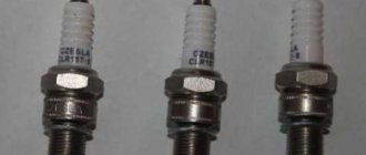
There are only 10 bolts on the cylinder head of Gazelle engines. Their caps have a diameter of 14 mm. After all the bolts have been tightened, you need to go through them again to make sure that they are all tightened as needed.
On ZMZ 406 and 405 models, pulling the bolts of the device is carried out in the following steps:
- Stage one. The parts of the device are pulled using a torque wrench with a force of 40-60 Nm.
Stage two. The threaded parts of the device are pulled with a force of 127 - 142 Nm.
Repair of the ZMZ-53-11 engine. Engine assembly. Part 3.
Repair of the ZMZ-53-11 engine. Engine assembly.
Part 3
Continuation. See the beginning of the article here: part 1, part 2
25. Install the oil sump with the gasket on the cylinder block and tighten the nuts securing it. Lubricate the joints of the rear oil seal holder and the timing gear cover with the block with sealant.
26. Install the water pump with the gasket in place. Place the tension pulley bracket onto the water pump mounting studs and secure the water pump housing to the timing gear cover.
27. the inner and outer pulleys and the fan spacer on the water pump hub Install two flat washers and one spring washer under the bolts. (When installing the fan, the flat washers are removed).
28. Install the oil pump with a gasket on the block, put a thrust sleeve on the long pin and secure the pump with two nuts and spring washers.
29. Install the gasoline pump with a gasket and screw it with two bolts.
30. Assemble the cylinder heads :
- a) place the valve spring support washers on the valve guides;
- b) press oil seals onto the guide bushings of the intake valves;
- c) install the valves in their seats to which they were ground;
- d) install valve springs. The springs are made with a uniform pitch along the entire length, so they can be installed on the head at any end;
- e) place spring plates on the valve springs;
- f) using a puller, compress the spring and insert the valve cotters into their seats;
- g) release the spring and remove the puller.
- For better running-in, lubricate the stems of new valves with graphite grease before assembly.
31. Remove the cylinder liner holders.
32. Place the cylinder head gaskets onto the head studs, press in the locating pins, install the heads and secure them with 18 nuts and flat washers. It is recommended to tighten these nuts in two steps: preliminary tightening by hand (all nuts evenly) and final tightening with a torque wrench with a tightening torque of 7.3 - 7.8 daNm (7.3 - 7.8 kgf m). Tightening of the head fastening nuts , both preliminary and final, is carried out in the order shown in Fig. 65.
33. Assemble the valve rocker arms with adjusting bolts and nuts.
34. Assemble the rocker axles :
- a) insert a cotter pin into one of the holes in the rocker arm axis and separate its ends;
- b) wipe and lubricate the rocker arm axle and valve rocker arm bushings with oil;
- c) put the gas distribution parts on the axle;
- d) insert a cotter pin into the second hole of the axle and separate its ends.
Assemble the axles in such a way that the holes for the fastening studs in the axle and struts are shifted away from the rocker arm adjusting bolts.
35. the valve tappets along the guides in the block and install them in their places . The lightly lubricated pusher should move smoothly into the guide under its own weight.
36. Insert the rods into the pushers.
37. Install the assembled rocker arm axles onto the cylinder heads. The adjusting bolts with their spherical part must be placed on the spheres of the upper tips of the rods. Tighten the nuts securing the rocker arm axles.
38. Place the side gaskets on the intake pipe mounting studs, and the front and rear gaskets of the intake pipe on the block. Lubricate the joints of the gaskets with sealant. Install the intake pipe assembly with the oil filter.
39. Tighten the two eye nuts .
40. fine fuel filter bracket with the filter assembly, the accelerator shaft with the bracket and levers assembly, and the accelerator spring bracket onto the studs for fastening the intake pipe. Tighten the intake pipe mounting nuts.
Tightening torques for threaded connections of the GAZ-3110 car — DRIVE2
An experienced mechanic or fitter does not need to measure the tightening torque. With experience, he already feels it. But sometimes on particularly important components you need to control yourself and use a torque wrench. This especially applies to such important components as tightening the main and connecting rod yokes, tightening the flywheel, tightening the cylinder head, tightening the propeller shaft nuts, etc. ZMZ-4062 engine Name of connection Tightening torque, N m (kgf m) Main bearing cover bolt 100-110 (10.0-11.0) Nut of connecting rod cap bolt 68-75 (6.8-7.5) Flywheel bolt 72-80 (7.2-8.0)
Cylinder head bolt:
– first stage 40-60 (4.0-6.0) – second stage 130-145 (13.0-14.5) Camshaft cover mounting bolt 19-23 (1.9-2.3) Crankshaft pinch bolt (ratchet) 104-128 (10.4-12.8) Camshaft gear mounting bolt 56-62 (5.6-6.2) Intake pipe mounting nut 29-36 (2.9-3.6) Front mounting bolt cylinder head covers 22-27 (2.2-2.7) Water pump pulley bolt 22-27 (2.2-2.7) Water pump bolt 22-27 (2.2-2.7) Gear wheel bolt intermediate shaft 22-27 (2.2-2.7) Nut securing the receiver to the intake pipe 19-23 (1.9-2.3) Nut securing the exhaust manifold 20-25 (2.0-2.5) Oil sump mounting bolt 12- 18 (1.2-1.8) when ensuring tightness, a moment is allowed
6 N m (0.6 kgf m)
Bolt for fastening the cylinder head cover 5.0-8.0 (0.5-0.8) when ensuring tightness, a torque of 3 N m (0.3 kgf m) is allowed. Bolt for fastening the oil seal holder 12-18 (1.2-1.8) Bolt fastening the fuel line with injectors 5.0-8.0 (0.5-0.8) Bolt fastening the inductive sensors 5.0-8.0 (0.5-0.8) Spark plug 31-38 (3.1-3.8 )Starter mounting bolt 67-75 (6.7-7.5) Generator bracket mounting nut 12-18 (1.2-1.8) Clutch pressure plate mounting bolt 20-25 (2.0-2.5) Clutch housing mounting bolt 42 -51 (4.2-5.1) Clutch housing amplifier mounting bolt 29-36 (2.9-3.6) Clutch release fork support mounting bolt 42-51 (4.2-5.1) Other connections Steering adjusting tube clamp nut traction 15-18 (1.5-1.8) Front suspension lower arm pin 180-200 (18-20) Front suspension upper arm axle nut 70-100 (7.0-10.0) Threaded joint pin nut 120-200 (12, 0-20.0) Bolt and nut for fastening the axle of the upper arms 44-56 (4.4-5.6) Bolt for fastening the wheel 100-120 (10-12) Nut for the flange of the drive gear of the rear axle 160-200 (16-20) Bolt for fastening the front suspension to the body 125-140 (12.5-14) Steering mechanism mounting nut 50-60 (5.0-6.0) Steering wheel mounting nut 65-75 (6.5-7.5) Steering mechanism bipod mounting nut 105- 120 (10.5-12) Bolt for fastening the pendulum arm bracket 50-62 (5.0-6.2) Bolt and nut for fastening the steering column to the instrument panel 12-18 (1.2-1.8) Steering wedge nut 18-25 (1.8-2.5) Suction fitting of the power steering pump 32-40 (3.2-4.0) Bolt fitting of the control valve of the built-in power steering 80-100 (8.0-10.0) Nut of the upper and lower discharge hose ends of the built-in power steering 44-62 (4.4-6.2) Nut of the upper and lower ends of the discharge hose of the built-in power steering 44-62 (4.4-6.2) Nut of the drain hose tube of the built-in power steering 44-62 (4.4-6.2) Nut connecting the tip of the injection hose and the hoses of the power cylinder of the separate power steering 32-40 (3.2-4.0) Bolt fitting for the drain hose of the built-in power steering 80-100 (8.0-10 ,0) Bolt for fastening the steering knuckle, lever and bracket 80-100 (8.0-10.0) Turn limiter 80-100 (8.0-10.0) Nut for fastening the axis of the brake and clutch pedal pusher 32-36 (3.2- 3.6) Rear brake shield mounting bolt 65-80 (6.5-8.0) Front brake caliper mounting bolt
110-125 (11,0-12,5)
Rear brake wheel cylinder mounting bolt 8.0-18.0 (0.8-1.8) Rear brake pressure regulator mounting nut 8.0-18.0 (0.8-1.8) Brake master cylinder mounting nut 24-56 (2 ,4-5.6) Vacuum booster mounting nut 8.0-18.0 (0.8-1.8) Bolt securing the splined yoke of the rear propeller shaft 50-56 (5.0-5.6) Nut securing the propeller shaft to the rear bridge 27-30 (2.7-3.0) Nut securing the intermediate support cross member to the body 27-30 (2.7-3.0) Bolt securing the intermediate support to the cross member 12-18 (1.2-1.8) Box mounting nut gears to clutch housing
50-62 (5,0-6,2)
* For other threaded connections, the tightening torques are as follows: - for M6 - 6–8 N m (0.6-0.8 kgf m) - for M8 - 14–18 N m (1.4-1.8 kgf m) — for M10 — 28–36 N m (2.8-3.6 kgf m)
— for M12 — 50–62 N m (5.0-6.2 kgf m)
There is a universal method for general purpose fasteners determined by the size of the key:
This information is available in scattered form, both on D2 and on the Internet, but when you sit in the garage and encounter difficulties in tightening bolts, everything is here in one place. I also have a Word file with signs (more cultured there), I can send to anyone who needs it. There was information about 402ZMZ too. I hope it helps someone. That's true for me. Don't be shy about liking.)))) Reliable fastening to everyone.)))
Repair of the ZMZ-53-11 engine. Engine assembly. Part 3.
Repair of the ZMZ-53-11 engine. Engine assembly.
Part 3
Continued. See the beginning of the article here: part 1, part 2
25. Install the oil sump with the gasket on the cylinder block and tighten the nuts securing it. Lubricate the joints of the rear oil seal holder and the timing gear cover with the block with sealant.
26. Install the water pump with the gasket in place. Place the tension pulley bracket onto the water pump mounting studs and secure the water pump housing to the timing gear cover.
27. the inner and outer pulleys and the fan spacer on the water pump hub Install two flat washers and one spring washer under the bolts. (When installing the fan, the flat washers are removed).
28. Install the oil pump with a gasket on the block, put a thrust sleeve on the long pin and secure the pump with two nuts and spring washers.
29. Install the gasoline pump with a gasket and screw it with two bolts.
30. Assemble the cylinder heads :
- a) place the valve spring support washers on the valve guides;
- b) press oil seals onto the guide bushings of the intake valves;
- c) install the valves in their seats to which they were ground;
- d) install valve springs. The springs are made with a uniform pitch along the entire length, so they can be installed on the head at any end;
- e) place spring plates on the valve springs;
- f) using a puller, compress the spring and insert the valve cotters into their seats;
- g) release the spring and remove the puller.
- For better running-in, lubricate the stems of new valves with graphite grease before assembly.
31. Remove the cylinder liner holders.
32. Place the cylinder head gaskets onto the head studs, press in the locating pins, install the heads and secure them with 18 nuts and flat washers. It is recommended to tighten these nuts in two steps: preliminary tightening by hand (all nuts evenly) and final tightening with a torque wrench with a tightening torque of 7.3 - 7.8 daNm (7.3 - 7.8 kgf m). Tightening of the head fastening nuts , both preliminary and final, is carried out in the order shown in Fig. 65.
33. Assemble the valve rocker arms with adjusting bolts and nuts.
34. Assemble the rocker axles :
- a) insert a cotter pin into one of the holes in the rocker arm axis and separate its ends;
- b) wipe and lubricate the rocker arm axle and valve rocker arm bushings with oil;
- c) put the gas distribution parts on the axle;
- d) insert a cotter pin into the second hole of the axle and separate its ends.
Assemble the axles in such a way that the holes for the fastening studs in the axle and struts are shifted away from the rocker arm adjusting bolts.
35. the valve tappets along the guides in the block and install them in their places . The lightly lubricated pusher should move smoothly into the guide under its own weight.
36. Insert the rods into the pushers.
37. Install the assembled rocker arm axles onto the cylinder heads. The adjusting bolts with their spherical part must be placed on the spheres of the upper tips of the rods. Tighten the nuts securing the rocker arm axles.
38. Place the side gaskets on the intake pipe mounting studs, and the front and rear gaskets of the intake pipe on the block. Lubricate the joints of the gaskets with sealant. Install the intake pipe assembly with the oil filter.
39. Tighten the two eye nuts .
40. fine fuel filter bracket with the filter assembly, the accelerator shaft with the bracket and levers assembly, and the accelerator spring bracket onto the studs for fastening the intake pipe. Tighten the intake pipe mounting nuts.
41. a bypass hose onto the fittings of the inlet pipe and water pump .
42. Reinstall the carburetor with the gasket and secure it with four nuts.
43. Install the pneumatic centrifugal speed limiter sensor with a gasket on the timing gear cover.
44. Install the fuel line pipes from the pump to the filter and from the filter to the carburetor. Install the tubes of the pneumatic centrifugal crankshaft speed limiter from the sensor to the carburetor, the sensor lubrication tube, and the oil filter discharge and discharge tubes.
45. Install exhaust manifolds with gaskets and tighten the fastening nuts. Install the starter screen under the right manifold mounting nuts.
46. Install the distributor drive and secure it with a holder and nut.
Install the distributor drive in the following order:
- a) set the crankshaft to the TDC position. compression stroke in the first cylinder (Fig. 66);
- b) insert the distributor drive into the hole in the cylinder block so that the slot in the drive shaft is directed along the engine axis and shifted to the left, along the direction of the vehicle;
- c) secure the ignition distributor drive housing with a holder and a nut so that the bracket with a threaded hole for fastening the ignition distributor is directed back and turned at an angle of 23° to the left from the longitudinal axis of the engine, as shown in Fig. 67.
47. Install the generator on the bracket and screw it using two bolts with washers and locknuts.
48. Place the alternator drive belt on the water pump and alternator pulleys and tighten it.
49. Place the water pump drive belt on the crankshaft, tension roller and water pump pulleys . Tension the belt using the tension roller.
50. Install the starter and screw it with two bolts.
51. Install the gearbox on the clutch housing, first placing the clutch release bearing on the front cover and secure it with four nuts.
52. Install the ignition distributor into the distributor drive housing. Installation should be carried out with the crankshaft position corresponding to TDC. in the first cylinder of the compression stroke; in this case it is necessary:
- a) before installing the distributor in place, check the gap in the contacts of the breaker and, if necessary, adjust it. The gap in the contacts should be within 0.3 - 0.4 mm;
- b) use the octane corrector nuts to turn the distributor body so that the arrow points to the zero scale mark;
- c) turn the distributor rotor so that it faces the terminals of the first cylinder. The first cylinder terminal on the ignition distributor cap is marked with the number 1;
- d) put the distributor cap with wires on the distributor and attach the wires to the spark plugs in the order of operation of the engine cylinders (1-5-4-2-6-3-7-8).
53. Attach the vacuum regulator tube to the carburetor and ignition distributor.
54. Adjust the gaps between the ends of the valve stems and the toes of the rocker arms. The gaps between the rocker arms and the valves on a cold engine (15 - 20 °C) should be 0.25 - 0.30 mm for the middle valves; for the outer valves (i.e., the first and eighth intake and fourth and fifth exhaust), the gap can be reduced up to 0.15 - 0.20 mm.
To adjust the clearances, it is necessary to set the crankshaft to the TDC position. in the first cylinder of the compression stroke when both valves are fully closed.
The gap is set in the following order: loosen the nut of the adjusting bolt on the rocker arm and, by rotating the adjusting bolt, set the required gap on the feeler gauge; Tighten the locknut while holding the bolt from rotating with a screwdriver.
Rotating the crankshaft a quarter turn each time, set the gaps between the valves and rocker arms of the remaining cylinders in the order of their operation (1-5-4-2-6-3-7-8).
55. Place rubber gaskets on the rocker covers, and install seals in the holes of the covers. Place the covers on the cylinder heads, put special washers on the seals and secure each cover with two nuts.
56. Place the wire holders on the brackets and place the high-voltage wires from the ignition distributor to the spark plugs in them.
57. Install oil separator and secure it with a bolt. Install the hoses of the main and additional ventilation branches.
58. On the right valve cover, close the oil filler neck with a cap with a sealing gasket.
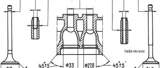
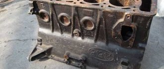
Formation of shells on the plane of the head
The main problem with the cylinder head is the formation of shells. On the plane of the head. Sinks are formed from the contact of the cylinder head with the coolant. Sinks can eat through the contact areas of the liner and the block head. What causes the breakthrough of gases from the combustion chamber.
If such damage occurs, head repair is necessary. The problem is eliminated by grooving the plane of the block head. But this is only if the depth of the shells allows them to be removed. Otherwise, the sink areas are fused using argon welding. And then the plane of the head is machined on a milling machine.
How to stretch the head on a GAZ 53
The procedure for tightening the gas cylinder head 53 from the center according to this diagram
It is advisable to make the first tightening with a little force. To pre-align the plane of the head relative to the cylinder block.
After the head is positioned correctly. You can repeat the tightening, but using a torque wrench. Also with a little effort. To press the head against the gasket and align the liners.
The tightening torque can now be increased to half the maximum tightening torque.
The GAZ 53 head is finally tightened with a tightening torque of 77-82 Nm
After some time, check the set tightening torque. And we perform a control broach with maximum effort.
The more uniformly the force is applied to each pin. The less likely it is that the threads in the cylinder block will break. Problem with threads being pulled out of the block. It becomes more relevant with each subsequent engine overhaul.
During the first and second overhaul of the engine, there is no need to worry about the studs. But every subsequent repair. Loosens the thread. Therefore, broaching must be done carefully and using a torque wrench.
Consequences of incorrect cylinder head installation
Correct tightening of the cylinder head is very important, since the performance of the motor directly depends on it. The cylinder head acts as a cylinder cover, and any violations in its fit affect the processes occurring inside the power unit.
Insufficient tightening of the head leads to a drop in compression due to loss of tightness at the junction of the cylinder head with the cylinder block, burnout of the gasket, breakthrough of working gases from the cylinders and their entry into the channels of the lubrication or cooling systems, penetration of technical fluids into the combustion chambers, which in turn is negative affects the functioning of the power unit and can cause very serious damage.
Excessive tightening also does not bring anything good; in this case, damage to the head often occurs - cracks appear, or fasteners are destroyed - bolts break, threads break, etc.
Uneven or incorrect tightening often causes warping of the head, due to which gaps appear at the junction of it with the block, which leads to the same consequences as insufficient tightening.
Process and order
Our resource advises novice motorists to think twice before tightening the cylinder head pins with their own hands. In practice, novice car enthusiasts, having no experience, begin the procedure without understanding how sadly it can turn out. Of course, in case of incorrect actions. Let's consider this procedure for a GAZ 53 car. Remember that each individual engine has its own operating nuances.
Required Tools
If you have already installed the cylinder head in place, then you will not need a whole set of tools. To tighten, you need to prepare one tool - a torque wrench. It is needed to carry out work, since it is only possible to correctly determine the moment with its help. Few people have such a tool at home, because it has a certain specificity of work. You can try asking the mechanics at the service station for it, but not for free. If you decide to purchase such a key for yourself, keep in mind that its cost is at least 1,200 rubles or 350 hryvnia.
Torque wrench
One more tip. Sometimes little-understood “auto experts” advise not to use a torque wrench, but to use a regular wrench. Their reasoning is that the screws need to be tightened to the maximum, and buying a torque tool is a waste of money. It can be said that they do not realize the seriousness of the situation. Therefore, if you want the repair process to go correctly, stock up on a torque wrench.
Step by step instructions
If you are the owner of a GAZ 53, we recommend using the service manual for the car. Perhaps the engine of your GAZ 53 has certain nuances in its operation or its own specifics. The instructions below are relevant for all GAZ 53. If you are ready to carry out these works, you can begin. If you changed the sealing gasket or repaired the motor, then reassemble it and install a new seal.
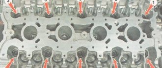
- Inspect the cylinder head bolts. They must be in perfect condition. If mechanical damage or signs of deformation are noticed on the screws, they need to be replaced. Reusing bolts is not recommended, but if their condition is ideal or close to it, then use of the pins is allowed. Pay attention to the thread - it must be clean. Pin sockets too. If you notice dirt or metal shavings on the elements, they need to be cleaned with a wire brush.
- The pins should be lubricated before tightening; motor fluid is suitable for this.
- Insert the screws into the holes and tighten them according to the order in the diagram. Using a torque wrench, all pins must be tightened to a torque of 7.3 - 7.8 kgm. Maintain order when doing this. If the temperature in the room where you are carrying out repairs is sub-zero (below -5 degrees), then the cylinder head tension moment should be 7.3 kgm. If it is 20 degrees, then the tension torque should correspond to the lower limit.
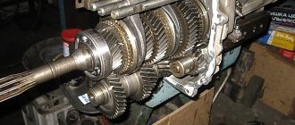
Disassembling the crankshaft
Disassembly of the crankshaft is required before grinding its journals and to replace the timing sprocket.
Use a puller to compress the coupling.
If there is no puller, remove it with blows through a brass mandrel.
Using a screwdriver, remove the rubber ring, having previously knocked the key out of the shaft slot.
We press the sprocket with a brass mandrel and, using a screwdriver, remove the sprocket key.
After grinding the crankshaft journals with a bolt with a “14” head and locked nuts, we unscrew the plugs.
We thoroughly clean the oil passages in the crankshaft from deposits and abrasive residues.
We wash the crankshaft channels with kerosene, gasoline or diesel fuel and blow with compressed air.
Screw the oil channel plugs into place
We use a beard to open the edges of the plugs
We assemble the shaft in reverse order. We begin pressing the sprocket and coupling by installing the corresponding keys into the groove of the crankshaft.
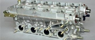
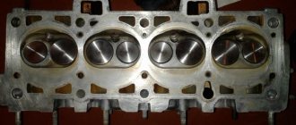
Part Features
The cylinder head is a structurally quite complex part. It is a massive plate in which there are channels for the circulation of fluids of the lubrication and cooling system, and technological holes - spark plugs, for injectors (in diesel engines), mounting holes.
Also on top of the cylinder head there is a so-called “bed” of the camshaft - a seat for its installation.
Despite its massiveness, the block head is a fragile part due to the voids inside, so excessive tightening force often leads to cracks in the walls and bridges.
For the manufacture of cylinder head, two types of metals are used - aluminum (the most common) and cast iron.
To secure the latter, steel bolts or studs with nuts are used. For example, the head of the UAZ 31519 block is secured with studs.
The difference in the materials used to make the head and its fasteners has one negative factor - different thermal expansion of the components when heated, especially for aluminum cylinder heads.
Uneven tightening of fasteners (nuts, studs, etc.) during thermal expansion leads to the appearance of excessive stress in the metal structure, resulting in warping of the head.
When is it necessary to puff?
Not every car enthusiast realizes the importance of this nuance. And not all drivers understand that they need to follow the order of tightening the cylinder head pins. This point is important, and it is not recommended to neglect it. If you are the owner of a GAZ 53 and have tightened the cylinder head screws incorrectly, this may cause other malfunctions. Accordingly, engine repairs will entail a lot of cash costs.
Truck GAZ 53
Ten years ago, the procedure for tightening the cylinder head screws in a vehicle was carried out by specialists during vehicle maintenance. Amendments were made to the legislation, according to which this procedure was abolished. Now tightening screws is a headache for car owners. In what cases should it be performed?
- If you notice that consumables, namely engine oil, are leaking from under the cylinder head. In some cases, this may be a consequence of mechanical damage to the head gasket. Or the gasket could simply be worn out. But sometimes oil leaks occur as a result of the cylinder head screws loosening.
- If you disassembled the engine of your GAZ 53. When assembling and installing the cylinder head, the torque and tightening order of the screws must be observed in any case. If this is not done, then during long-term operation of the cylinder head, its deformation may occur.
Note that experienced car enthusiasts recommend that all drivers, without exception, periodically check the quality of bolt tension.
If you see that the bolts can be tightened, then this needs to be done. The cylinder head screws can become loose at random while the vehicle is in use. Therefore, it is necessary to diagnose tension once every 3 thousand kilometers.
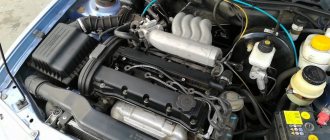
Replacing UMZ 4216 engines
If they purchase a Gazelle with an unsuccessful engine, car owners try to get rid of the power unit by replacing it with an internal combustion engine of another model. Many different options can be considered as a replacement, but most often owners of commercial vehicles install ZMZ-405 engines; this particular engine is chosen for a number of reasons:
- the Trans-Volga engine is not capricious - it “digests” Russian fuel well and does not break down often;
- relative to imported power units (Cummins, Toyota, Nissan), the ZMZ-405 is inexpensive;
- When installing the ZMZ, a minimum of rework is required.
Recently, Gazelle Business cars have been equipped with a Cummins turbodiesel as standard, but owners of cars with UMZ-4216 almost never consider this engine as a replacement:
- Cummins doesn't come cheap;
- The American engine is very sensitive to the quality of fuel, and if the car is fueled with bad diesel fuel, the Cummins can quickly fail.
Another advantage of the ZMZ-405 (or 406) is that many used engines in good working condition are sold on the secondary market, and their price is several times lower than a new internal combustion engine. True, when buying a used unit there are no serious guarantees - you have to take the seller’s word for it. Repair of UMZ 4216 engine; Replacing the cylinder head (gasket) Gazelle gasket. But even if the 405 requires minor repairs (replacing chains or piston rings), purchasing it along with repairs is still much cheaper than purchasing an expensive imported engine. Replacing the cylinder head gasket of a VAZ 2110. Another disadvantage of an imported internal combustion engine is that if it was not installed as standard on the Gazelle, you will have to purchase it together with the gearbox or be puzzled by the adjustment of mounting the Gazelle gearbox to the new engine.
Replacing the cylinder head gasket of the ZMZ-406 engine
Typically, the head gasket is changed in case of the following damage: — Gas breakthrough into the cooling system;
— Oil getting into the cooling system;
— Insufficient compression in one or more cylinders (less than 1 MPa).
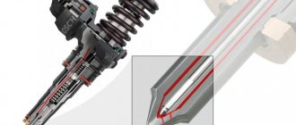
Removal
The cylinder head can be removed with the receiver and exhaust manifold.
If the cylinder head is removed from an engine installed on a car, you must first perform the following operations:
Disconnect the fuel supply and drain lines.
Remove the battery.
Drain the engine cooling system.
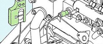
7. Disconnect the phase sensor connector from the wiring harness.
Unscrew the screws and disconnect the wires from the oil pressure indicator sensors 1 and emergency oil pressure sensors 2.
Disconnect the connectors from the engine temperature sensors 5, the coolant temperature indicator 4, and the coolant overheat indicator 3.
Loosen the clamp and remove the hose to the expansion tank from fitting 6 of the thermostat.
Loosen clamp 1 and remove hose 2 from the fitting to the check valve of the vacuum brake booster.
Disconnect connector 3 from the throttle position sensor.
Unscrew nut 1 and remove the blue ground wire from the stud at the front end of the receiver.
Unscrew nut 4 and pull out accelerator cable 3 from the air throttle valve drive sector.
Disconnect plug 2 from the wiring harness, located between the engine intake pipes, the speed sensor and the crankshaft synchronization sensor installed near the crankshaft pulley ring gear.
Move the cable gland 3 from the threaded end 2 of the cable shell, unscrew the nut 1 securing the cable end and pull out the end 2 from the bracket fixed to the engine intake pipe, sliding it back.
Then remove the accelerator cable from the bracket upwards.
Bend the accelerator cable holder and remove the cable from it.
Move the accelerator cable away from the engine.
Disconnect the wires from the generator.
Disconnect connector 1 from the idle speed control.
Unscrew nut 2 and remove the ground wires from the stud at the rear end of the receiver.
Disconnect connector 1 from the air temperature sensor.
Loosen clamp 2 and remove the coolant supply hose from the heater tap fitting
source
re-pulling the cylinder head
Hello again :) However, I am often asked, “Do I need to re-broach the cylinder head?” There are many who think that they put the head on, tighten it and don’t touch it anymore.
In the course of my rather long work as a motor mechanic, and this is already more than a quarter of a century, I was convinced from my own experience that if you are too lazy to pull the head through the time set for pulling it, then after some more time, and this largely depends on the driving style the driver and the distance traveled simultaneously will have to be removed.
Usually the gasket burns out within a year, and if a person travels a long distance, then even after a month. So my advice is this: don't drive very far with the head loose, otherwise you'll have to remove it on the road. But you know, I noticed that if the equipment came straight from the factory, then after the required mileage for broaching, the heads rarely weaken. It is possible that the material of the gasket that is installed there is different.
So how long does it take to pull the cylinder head? On average after a thousand km. mileage This is written in the instructions and this is confirmed by practice. In the instructions for this. It is also written that after ten thousand you need to re-tighten or check the head broaching.
Well, in most cases, one pull was enough. But rarely, of course, but there were cases that when the gasket burned out, the head was weak even after one pull. In my opinion, it all depends on the material of the cylinder head gasket, which shrinks a lot, and which doesn’t sink at all.
The physics of this phenomenon, namely the weakening of the head broach, is obvious. Typically, cylinder heads are aluminum, and the mounting bolts or studs are also steel. When heated, aluminum has a greater coefficient of expansion than steel, and when the engine heats up, the expanding head compresses the gasket like a press, and when it cools down, it also releases and the gasket is already compressed, and the bolts are naturally loosened.
There is a rule: you cannot pull a hot engine, only a cold one. I’ll tell you a list of engines that need to be pulled from my experience with which I dealt, namely: ZMZ405,406,409. engines ZMZ-402, UAZ 417,421. Engines ZMZ 511,512,523, ZIL-130, Ural.
I won’t say anything about others, but usually VAZ heads rarely sag. I can’t say anything about foreign cars either, because I haven’t looked through them much, and I don’t want to waste it. That's all for now.
No, that's not all. In order to avoid the hassle of re-pulling the head, you have to disassemble almost half of the engine in order to make sure that it is not loose, but sometimes this happens. Depends on the gasket material. You won't guess right away.
In order not to re-stretch the heads, you can install a metal package. You can read about that here. And although I wrote about the UAZ-Patriot, this can apply to many engines. Good luck friends!
Tightening torque cylinder head tightening force gas 53
Hello dear friends! Today we will finally finish the series of articles related to the “Major overhaul” of the ZmZ 511 engine and modifications (Gaz 53). In the last article, we installed the pistons and connecting rods in place. Now all we have to do is close the pan, the front cover with the pump, replace the cylinder head (cylinder head) and close the plate (spider). And with this our engine will be ready for installation on the car. Let's look at everything in order.
After you are done with the crankshaft and pistons, do not forget to put the oil receiver in place before closing the pan. Before installing the oil receiver, change the rubber sealing ring. Usually, after prolonged use and exposure to oil, it becomes tanned, that is, it becomes hard. Therefore, during a major overhaul, it is better to replace it.
Oil receiver Gas 3307, Gas 53.
Now you need to close the front cover. But first we need to replace the crankshaft oil seal, which is installed in the front cover. The front cover oil seal, like all oil seals, is made of special oil-resistant rubber, but over time it also hardens, cracks, and wears out. Therefore, it also needs to be replaced. The rubber seal of the front cover of the ZMZ 511 (Gaz 53) engine is pressed into a special iron frame.
Front cover seal ZMZ 511 (Gas 53).
And so, after replacing the front cover oil seal, you can close the front cover, having first replaced the gasket. Yes, I almost forgot, before you install the front cover, be sure to pay attention to the rubber seal that is installed with the crankshaft pulley flange key.
Over time, it also becomes tanned and, accordingly, also needs to be replaced during a major overhaul. Many people don’t even know that such a seal exists. So, if it is not installed or replaced, then there may be an oil leak.
Installing the intake manifold
Then the intake manifold and all accessories are installed. The intake manifold is mounted on rubber gaskets. It cannot be overtightened. The gaskets will be squeezed out. If you do not hold on, a coolant leak will occur. And a torque wrench won't help here. The effort is very weak. It is better to stretch the intake manifold twice. Preliminarily with a force that does not allow the gasket to be squeezed out. Then let it sit for a bit. So that the elastic takes its place. And then again literally half a turn of the nut. But again you need to monitor the gasket.