Strict necessity
The automatic transmission is designed in such a way that almost all manipulations in it occur with the help of oil injected under pressure. The pressure is pumped up by a special oil pump, which in its structure and design resembles an engine cooling pump and works in a similar way.
The oil circulates at incredible speed. To at least roughly imagine what this speed is, you need to open a water tap and in your imagination increase the pressure and pressure of this water several tens of times.
An inexperienced motorist, and indeed a person who does not repair automatic transmissions on his own, will have a logical question: why is such high pressure needed, and why is it so useful when operating an automatic transmission?
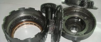
In fact, all movements of the clutches, which are similar in principle to the gear shafts of mechanical transmissions, are carried out precisely due to a powerful jet of oil. This oil flows through a system of automatically shutting channels called solenoids. Depending on the path for oil provided by the solenoid, the clutches move under pressure in such a way that they eventually form packages that connect the engine and wheels in a certain way.
When an automatic transmission is operating, the oil inevitably heats up: this is caused simultaneously by high pressure in the oil channels and strong friction achieved when connecting the clutches and their synchronous movement. The temperature sensor allows the automatic transmission control unit to receive data about the state of the technical fluid in the crankcase and how efficient the entire functional unit is.
Auxiliary automatic transmission control sensors
In addition to the main sensors related directly to the gearbox, its electronic control unit can also use information obtained from additional sources. Typically these are the following sensors:
The combination of automatic transmission sensors ensures its proper operation and comfort during vehicle operation. If sensor malfunctions occur, the balance of the system is disrupted, about which the driver will be immediately warned by the on-board diagnostic system (i.e., the corresponding “error” will light up on the instrument cluster). Ignoring malfunction signals can lead to serious problems in the main components of the car, therefore, if malfunctions are detected, it is recommended to immediately contact a specialized service.
Operating principle of the sensor
The operating principle of the sensor is as follows:
- You change the position of the selector lever.
- The position taken by the curtain is recorded in an electronic device. At the same second, it transmits this data to the electronic control unit of the machine.
- The program is launched in the on-board computer.
- According to the given signal, the hydraulic system begins to work. The necessary valves open, the brake band clamps the friction discs, and the desired gear is engaged.
This is how the gear selector position device works. But in addition to its main function, it is responsible for some components of the car. More on this in the next block.
What is the sensor responsible for?
The selector lever position sensor is a multifunctional device. The signal from it turns on the reversing lamps. The inhibitor controls the operation of the starter drive in the “P” and “N” positions. That is why the serviceability of the device is important.
The driving mode is determined using a potentiometer. The resistance of the device depends on the position of the slider. At the same time, the output voltage also changes. And the voltage directly works with the valve body valves, opening or closing them.
Where is it located?
It can be found on the device selector shaft. In most cases it is connected to the spool valve actuator in the hydraulic plate.
Attention! The sensor is opened by drilling out rivets.
Now you know what the device is and how to find it. Next, I will talk about common causes of device malfunctions and point out signs of failure.
In the meantime, write in the comments whether you have already disassembled the automatic transmission selector position sensor or replaced it?
Sensors in the automatic transmission
So, the main task is the smooth operation of the automatic transmission, speed of response, minimizing wear of loaded automatic transmission elements, etc.
Simply put, the electronic system must change gears at the most appropriate moment.
It is quite obvious that to implement such a task it is necessary to take into account a number of individual parameters. For this reason, the automatic transmission control unit is programmed in such a way as to dynamically select the most suitable transmission operating mode, taking into account the readings that are recorded and transmitted by the sensors.
In an automatic transmission, the main sensors are:
- speed sensor. This sensor is necessary to determine the rotation speed of the input and output shaft of the box;
- Automatic transmission oil pressure sensor, transmission fluid temperature sensor;
- automatic transmission selector position sensor, which is also called automatic transmission inhibitor or automatic transmission shift sensor;
- The automatic transmission control unit is closely connected to the ECM of the entire vehicle, which allows it to receive information from other sensors.
The automatic transmission speed sensor is one of the main elements. Often there are two such sensors, one “reads” the speed of rotation of the primary (input) shaft, while the other transmits to the ECU data on the speed of rotation of the output shaft or differential gear on automatic front-wheel drive cars.
As for the automatic transmission ECU, information from the first sensor allows the controller to determine the degree of load on the internal combustion engine and select the most suitable gear. Readings from the second sensor are needed in order to monitor the operation of the gearbox (how the ECU command is executed, whether the desired gear has been engaged, etc.)
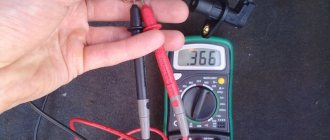
If we talk about the speed sensor and its design, such an element is a well-known Hall sensor. Frequent problems include damage to the housing and problems with contacts. However, it will not be possible to quickly check the speed sensor with a multimeter, so during diagnostics it is recommended to install a known-good element.
Let us also add that on some cars you can also find an inductive speed sensor. The sensor works on the principle that when a gear tooth of the gearbox passes through the magnetic field of the sensor, voltage appears in the coil. This voltage forms a signal and is transmitted to the ECU.
The block takes into account the total number of gear teeth, which allows you to calculate the current speed. It is important to understand that the Hall sensor is visually similar to an inductive one, but the second option is very different in operating principle, it generates an analog signal, does not use a reference voltage, etc. By the way, the inductive sensor can be checked with a multimeter.
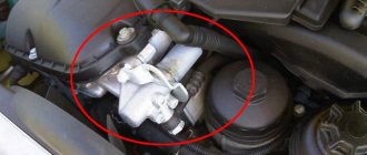
- The automatic transmission selector position sensor is necessary for the control unit to “switch on” the appropriate operating mode of the box. In other words, this sensor allows the unit to determine how to operate the hydraulic system, taking into account the position of the automatic transmission selector (PNRD-2-1, manual control M +/-, etc.).
Often the specified sensor is called an automatic transmission inhibitor. This sensor is usually located on the gearbox selector shaft. Also, on some automatic transmissions it can be connected to the mode selection spool valve drive in the valve body itself.
The automatic transmission selector position sensor is also responsible for turning on the reversing lights and controls the operation of the starter drive in the selector positions P and N. If we talk about the device, such sensors may differ, but they are often based on a potentiometer that changes the resistance depending on the position there is a selector.
In a nutshell, the sensor consists of resistive plates and a movable slider directly connected to the selector. Taking into account the position of the slider, the resistance of the sensor also changes, which also leads to a change in the output voltage.
As a rule, over time, this sensor may become unusable or begin to work incorrectly. In some cases, disassembling the closed case and carrying out preventive maintenance helps, but after this further malfunctions are possible. For this reason, experts recommend immediately replacing the automatic transmission selector position sensor.
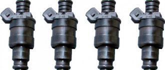
- Temperature and pressure sensors record parameters directly related to ATF. An automatic transmission temperature sensor is necessary because the operation of friction clutches greatly depends on the properties of the working fluid, oil level and temperature.
In simple words, to protect the clutches and gearbox from overheating, a thermistor is installed that can change the resistance when the temperature changes. It turns out that the sensor voltage changes depending on the ATF temperature, and the corresponding signals are transmitted to the ECU.
The automatic transmission temperature sensor is installed in the gearbox housing or integrated into the wiring inside the automatic transmission housing. If, according to sensor readings, the ECU detects significant overheating, the automatic transmission usually goes into emergency mode.
As for the automatic transmission pressure sensor, indicated sensors are usually installed in the valve body channels, measure pressure readings and transmit electrical signals to the automatic transmission electronic control unit.
Such sensors can be discrete and analog. The first type registers deviations from certain parameters during automatic transmission operation. Normally, the sensor contacts are closed; if the pressure drops at the location of the sensor, the contacts will be open, the ECU receives a signal and increases the pressure.
An analog sensor takes into account changes in pressure more flexibly by sending different signals. This allows the unit to more accurately make the necessary adjustments, affecting the operation of the automatic transmission.
- In the list of sensors that are used to control the automatic transmission, the electronic control unit of the automatic transmission also receives signals from other ECM sensors. For example, the unit receives signals from the brake pedal sensor to lock the selector when turning on the “parking” mode, the accelerator pedal position sensor (if the gas pedal is electronic), the TPS to determine the current load on the internal combustion engine and select the most suitable gear, etc.
Gear shift sensor in automatic transmission: features, principles
It is a mechanism that is responsible for the peculiarities of transmitting information about the position of the lever responsible for switching speeds to the box controller. The meter is also responsible for controlling other elements.
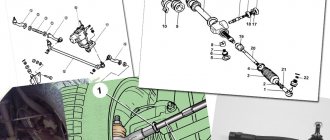
In most cases, the gear sensor is located in the area of the selector shaft.
Automatic transmission selector position sensor
The machine contains several types of devices that monitor the parameters of the gearbox so that deviations do not occur. When any part breaks or the device fails, it sends a signal to the control panel monitor.
Automatic transmission sensors:
- device for determining speed. Determines the rotation speed of the input and output shafts;
- lubricant pressure and automatic transmission temperature sensors;
- ECU. The electronic control unit is the brain of the vehicle system;
- and, finally, the automatic transmission inhibitor we need or the selector position sensor.
The position sensor consists of resistive plates and a slider that moves.
Attention! The automatic transmission selector position device is a sealed device, which is better not to disassemble, but to replace completely. Since disassembly and reassembly can lead to subsequent system failures. And a hacked inhibitor is difficult to configure to function adequately.
Speed sensor
Speed sensor
As a rule, two speed sensors are installed in an automatic transmission. One records the rotation speed of the input (primary) shaft, the second measures the rotation speed of the output shaft (for a front-wheel drive transmission, this is the rotation speed of the differential gear). The automatic transmission ECU uses the readings of the first sensor to determine the current load on the engine and select the optimal gear. Data from the second sensor is used to monitor the operation of the gearbox: how correctly the commands of the control unit were executed and exactly the gear that was needed was engaged.
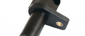
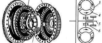
The design of the Hall sensor and its signal shape
Structurally, the speed sensor is a magnetic non-contact sensor based on the Hall effect. The sensor consists of a permanent magnet and an integrated Hall chip located in a sealed housing. It records the rotation speed of the shafts and generates signals in the form of alternating current pulses. To ensure the operation of the sensor, a so-called “pulse wheel” is installed on the shaft, which has a fixed number of alternating protrusions and depressions (quite often this role is played by a regular gear). The principle of operation of the sensor is as follows: when a gear tooth or wheel protrusion passes through the sensor, the magnetic field it creates changes and, according to the Hall effect, an electrical signal is generated. It is then converted and sent to the control unit. A low signal corresponds to a depression, and a high signal corresponds to a protrusion.
The main malfunctions of such a sensor are depressurization of the housing and oxidation of the contacts. A characteristic feature is that this sensor cannot be “ringed” using a multimeter.
Less commonly, inductive speed sensors can be used as speed sensors. The principle of their operation is as follows: when a gear tooth passes through the magnetic field of the sensor, a voltage arises in the sensor coil, which is transmitted to the control unit in the form of a signal. The latter, taking into account the number of gear teeth, calculates the current speed. Visually, an inductive sensor is very similar in appearance to a Hall sensor, but has significant differences in the signal shape (analog) and operating conditions - it does not use a reference voltage, but produces it independently due to the properties of magnetic induction. This sensor can be “ringed”.
Temperature sensor
Transmission temperature measurement is not used on all vehicles. The main functions that the sensor provides:
- prevention of torque converter overheating and thermal damage to clutches>;
- optimal heating of the automatic transmission in winter conditions;
- adjusting the operating mode of the gearbox when approaching a critical temperature;
- more accurate choice of settings for chip tuning>;
- display of information to the car owner.
The main symptoms of incorrect temperature measurement are:
- The automatic transmission cannot be taken out of emergency mode;
- when the operating temperature is reached, the emergency mode is triggered;
- constant indication of automatic transmission overheating;
- Shocks when driving when cold.
For accurate diagnosis, reading the error with a special scanner is required. If the equipment is missing, you can check the sensor by replacing it with a known good one. You should also visually inspect the contacts and housing for mechanical damage.
It is prohibited to use a vehicle with faulty automatic transmission sensors. In addition to the loss of comfort from driving a car, as a result of the ECU receiving unreliable information, the car's power plant can suffer serious damage. The safety of the car is also reduced, since slipping and jerking while changing gear ratios can cause the driver to skid and lose control.
Range Sensor: Features
In order to make sure that the box is working properly, you need to check the adjustment of the box range meter. This procedure is available using special diagnostic complexes and systems. The transmission range meter is used to transmit a signal about the position of the selector lever to the TCM. The position of the selector lever is assessed based on data analysis, in particular a transmission range meter.
Pressure meter
To determine the intensity of circulation of the working fluid in the automatic transmission, a pressure sensor may be provided in the system. There may be several of them (for different channels). The measurement is carried out by converting the pressure of the working fluid into electrical signals, which are supplied to the electronic control unit of the gearbox.
There are two types of pressure sensors:
- Discrete – record deviations of operating modes from a given value. During normal operation, the sensor contacts are connected. If the pressure at the location where the sensor is installed is lower than required, the sensor contacts open, and the automatic transmission control unit receives the corresponding signal and transmits a command to increase the pressure.
- Analog – converts the pressure level into an electrical signal of the appropriate magnitude. The sensitive elements of such sensors are capable of changing resistance depending on the degree of deformation under pressure.
Auxiliary automatic transmission control sensors
In addition to the main sensors related directly to the gearbox, its electronic control unit can also use information obtained from additional sources. Typically these are the following sensors:
- Brake pedal sensor - its signal is used when the selector is locked in the “P” position.
- Gas pedal position sensor – installed in the electronic accelerator pedal. It is necessary to determine the current driving mode request from the driver.
- Throttle position sensor – located in the throttle body. The signal from this sensor shows the current operating load of the engine and influences the choice of the optimal gear.
The combination of automatic transmission sensors ensures its proper operation and comfort during vehicle operation. If sensor malfunctions occur, the balance of the system is disrupted, about which the driver will be immediately warned by the on-board diagnostic system (i.e., the corresponding “error” will light up on the instrument cluster). Ignoring malfunction signals can lead to serious problems in the main components of the car, therefore, if malfunctions are detected, it is recommended to immediately contact a specialized service.
Signs of a broken gear shift sensor
What can cause a sensor to fail? The reason may be abrasion of contacts due to constant use of the lever, or water getting inside due to a leak, especially if the crankcase protection is not installed. If the gear shift sensor fails, the control unit stops receiving information about the position of the selector. There are several signs that the sensor is faulty:
• the “HOLD” light on the dashboard is active, the automatic transmission goes into emergency mode. Turning off the engine and starting it again does not solve the problem.
• There is only a shift to first speed, there are no other shifts.
• When driving, there are no gear changes, either up (from 2 to 3, from 4) or down (from 4 to 3, from 3 to 2).
Additional automatic transmission sensors
In addition to the main sensors, the design includes additional sensors. They belong to the gearbox. The information received from these sensors can also be used by the electronic control unit. Auxiliary sensors include:
- Brake pedal sensor;
- Gas pedal position sensor;
- Throttle position sensors.
The brake pedal sensor is used when the selector lever is locked when it is in the “P” position. The gas pedal position sensor is installed in the electronic accelerator pedal and is necessary to determine the current driving mode request from the motorist. But the throttle position sensor is already located in the throttle body itself and is used to display the current operating load of the engine. It also influences the choice of the optimal gear. Together, all these sensors ensure the correct operation of the systems and the vehicle. If a problem occurs in any of the sensors, the overall operation of the entire system is disrupted. Information about this usually appears on devices in the form of an error. Under no circumstances should you ignore such vehicle calls, as this can lead to more serious problems in the main components of the vehicle.
More details about automatic transmission sensors will be discussed in this video:
Causes of failure
- erasing contacts;
- if water gets inside due to a leak;
- in the absence of protection.
If the meter fails, the information does not reach the control unit.
Gear shift sensor in automatic transmission: features, principles
It is a mechanism that is responsible for the peculiarities of transmitting information about the position of the lever responsible for switching speeds to the box controller. The meter is also responsible for controlling other elements.
In most cases, the gear sensor is located in the area of the selector shaft.
Causes of failure
- erasing contacts;
- if water gets inside due to a leak;
- in the absence of protection.
If the meter fails, the information does not reach the control unit.
Signs of breakdown
- if the device is broken, switching speeds up and down is not possible;
- the “HOLD” light is on;
- Restarting the engine does not solve the problem.
If the device fails, its replacement is indicated, which is best carried out by qualified services. Experienced specialists will determine the cause of the breakdown, help with repairs and efficiently replace such a meter.
Sensor replacement technology
We move the selector lever to “N”, remove everything under the hood that may interfere with access: battery, air filter, etc. We disconnect the rod to the gear selection rod and fix it to avoid spontaneous gear shifting.
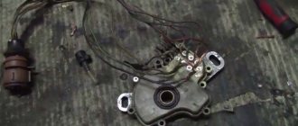
Slightly loosen the rod nut, reducing the fit on the shaft. And now, carefully, with swinging to the sides, we remove the rod from the rod. Disconnect the electrical connector of the sensor. We free the sensor body from extraneous “overlays” that prevent its removal. This could be an oil level dipstick guide, an electrical connector casing, etc., it all depends on the design features of the car. Now use the appropriate heads to unscrew the pin and bolt securing the sensor. Rocking from side to side, remove the automatic transmission gear shift sensor . All. The old one is for disposal, the new one is in its place. Assembly is carried out, as you might guess, in the reverse order.
What types of automatic transmission sensors are there and how do they work?
Among the main goals of automatic transmission control, one can highlight the determination of the optimal gear shift moment. To achieve this, there are always some factors to consider. In modern designs, a dynamic control program is provided for this. With its help, you can select the appropriate mode, which will depend directly on operating conditions and the current driving mode, which are determined by sensors. The main ones in an automatic transmission are speed sensors, pressure and temperature sensors of the working fluid, as well as a selector position sensor. Each of them has its own purpose and, accordingly, its own design.