Why does a diesel engine need a governor?
There is no control rack position for a diesel engine that would allow the diesel engine to accurately maintain its speed without the aid of a governor. At idle, for example, without a speed controller, the engine speed will either drop until the engine stops, or will continue to increase, eventually causing the engine to self-destruct.
The latter possibility is due to the fact that the diesel engine operates with excess air, which means that there is no effective throttling of the mixture entering the engine as its speed increases.
For example, if a cold engine is started and left to idle while the initial amount of fuel continues to be injected, then the characteristic friction will soon begin to decrease. The same applies to the engine load from the units driven from it, such as a generator, air compressor, fuel injection pump, etc. This means that if the position of the control rack remains unchanged and the rack is not retracted to reduce the amount of fuel supplied (as a governor would do), then the engine speed will increase more and more (due to the above drop in friction) until it reaches the point self-destruction. In other words, it is mandatory that the diesel engine be equipped with a speed controller. Currently, in-line injection pumps use either mechanical (centrifugal) regulators or an electronic diesel control (EDC) system.
Pneumatic regulators controlled by intake manifold pressure were previously installed on small fuel injection pumps. They had to be abandoned as a result of increased demands on the accuracy of regulation and on the operation of the regulator.
Design of the injection advance device
The injection advance device for an in-line injection pump is installed directly at the end of the injection pump cam shaft. The main differences between injection advance devices are open type and closed type.
The closed-type injection advance device has its own lubricating oil reservoir, which makes the device independent of the engine lubrication system. The open design is connected directly to the engine lubrication system. The body of the device is screwed to the gear, and the compensating and adjusting eccentrics are installed in the body so that they rotate freely. The compensating and adjusting eccentrics are guided by a pin, which is rigidly connected to the body. In addition to lower price, the “open” type has the advantage of requiring less space and lubricating more efficiently.
What is the injection pump used for?
The main difference between a gasoline unit is the ignition of the combustible mixture inside the cylinders. In a gasoline engine, the mixture is ignited by spark plugs. In a diesel engine, the mixture spontaneously ignites under compression. The injection pump is needed for the timely supply of diesel fuel to the cylinders at the moment of compression.
By design, injection pump pumps differ as follows: in-line type, main type and distribution type. In an in-line engine, diesel fuel is pumped into each cylinder from its own pair of plungers. The distributor provides all cylinders with one or two pairs of plungers. Mainline devices are used to pump diesel fuel into the fuel accumulator.
Remember, injection pump and injectors are the main elements of the diesel ignition system. They are present in most diesel units and are of the electronic type.
Checking and adjusting the gas distribution mechanism
The correct installation of timing parts (drive gears, camshaft, pushers, rods, levers, valves) is ensured by fixing the drive gears on the crankshaft and camshaft, fixing the camshafts and setting the gap between the levers and valves, between the cam washers and the pushers.
When the valve timing parts are installed correctly, the valve timing (the timing of the opening and closing of the intake and exhaust valves relative to the crankshaft crankshaft) exactly corresponds to the pie chart of the valve timing drawn up by the builder.
Typically, a violation of the valve timing during diesel operation is unlikely, since all drive parts are fixed and marked with special marks. A violation of the gas distribution can occur after disassembling the gas distribution parts during repairs and especially when replacing drive gears.
To check the correct installation of the gas distribution, the movement parts of the first cylinder are installed in the c. m.t., then turn the crankshaft against the direction of rotation at an angle corresponding to the advance angle of the intake valve opening, according to the valve timing diagram. With this position of the gas distribution parts, a feeler plate with a thickness of 0.03-0.05 mm is placed between the cam washer and the pusher roller. If, when turning the crankshaft in the direction of correct rotation, the plate “bites” and the lever rests on the valve stem, then the gas distribution is set correctly. Usually there is no need to check the opening of the exhaust valve and the valves of the remaining cylinders, as well as to check the gas distribution of the diesel engine in reverse, since the cam washers of the forward and reverse strokes of the intake and exhaust valves are either forged together with the camshaft or jammed on the camshaft one relative to the other under a certain angle.
Installation of the cam washers is ensured by their tight fit on the camshaft on the keys and fixation with a special pin, the ends of which are slightly riveted.
To ensure a tight fit of the valve in the seat when installing gas distribution parts, a thermal gap is installed between the lever and the valve stem to allow free extension of the valve. Typically, the clearance for the exhaust valve is slightly larger than for the intake valve, since the former heats up more. During diesel operation, thermal clearances are periodically checked and adjusted by tightening or unscrewing the impact bolt on the lever or changing the length of the pusher rod.
Diesel injection systems
Conceptually, internal combustion engines - gasoline and diesel - are almost identical, but there are a number of distinctive features between them. One of the main ones is the different occurrence of combustion processes in the cylinders. In a diesel engine, fuel ignites due to exposure to high temperatures and pressure. But for this it is necessary that diesel fuel is supplied directly to the combustion chambers not only at a strictly defined moment, but also under high pressure. And this is provided by diesel engine injection systems.
The constant tightening of environmental standards and attempts to obtain greater power output with lower fuel costs ensure the emergence of ever new design solutions in the diesel fuel system.
The operating principle of all existing types of diesel injection is identical. The main power elements are the high-pressure fuel pump (HFP) and the injector. The task of the first component is to inject diesel fuel, due to which the pressure in the system increases significantly. The nozzle ensures the supply of fuel (in a compressed state) to the combustion chambers, while atomizing it to ensure better mixture formation.
It is worth noting that fuel pressure directly affects the quality of combustion of the mixture. The higher it is, the better the diesel fuel burns, providing greater power output and less pollutants in the exhaust gases. And to obtain higher pressures, a variety of design solutions were used, which led to the emergence of different types of diesel power systems. Moreover, all the changes concerned exclusively the two indicated elements - the injection pump and injectors. The remaining components - tank, fuel lines, filter elements, are essentially identical in all available types.
Pump injectors
Pump injectors can be considered a separate branch in diesel power systems, since the injection pump design as such is not used.
The peculiarity of this system is that the nozzle and plunger pair are combined into a single structure. The drive of the section of this fuel unit is carried out from the camshaft.
It is noteworthy that such a system can be either completely mechanical (injection control is carried out by a rack and regulators) or electronic (solenoid valves are used).
Pump nozzle
A variation of this type of injection is the use of individual pumps. That is, each injector has its own section, driven by the camshaft. The section can be located directly in the cylinder head or placed in a separate housing. This design uses conventional hydraulic nozzles (that is, the system is mechanical). Unlike injection with a high-pressure fuel pump, the high-pressure lines are very short, which made it possible to significantly increase the pressure. But this design was not particularly widespread.
The positive qualities of power pump injectors include:
- Significant indicators of the created pressure (the highest among all injection types used);
- Low metal consumption of the structure;
- Accuracy of dosage and implementation of multiple injections (in injectors with solenoid valves);
- Possibility of engine operation if one of the injectors fails;
- Replacing a damaged element is not difficult.
But there are disadvantages to this type of injection, including:
- Unrepairable pump injectors (if they break down, they need to be replaced);
- High sensitivity to fuel quality;
- The pressure generated depends on the engine speed.
Pump injectors are widely used in commercial and truck vehicles, and this technology has also been used by some passenger car manufacturers. Nowadays it is not used very often due to the high cost of maintenance.
Other methods of bleeding the fuel system of a diesel engine
So, above we looked at the main way to bleed a diesel fuel system. At the same time, many specialists and experienced car enthusiasts separately point out that in some cases such attempts to bleed the pump can have serious consequences for the power system.
Please note that the reason for this concern is that if there is mechanical damage, bleeding in this manner can cause irreparable damage. Let's look at other existing methods
First of all, the bolt on the fuel return line (the so-called “return”) is loosened. Next, you should carefully monitor how the fuel comes out. If air bubbles are visible, then this means that the system is airy.
If so, you can use a simple tire inflator or compressor. Next, the hose is removed from the fuel pump and the air pump hose is installed in its place. The basic idea is that pumping occurs, which allows the pressure in the system to increase. This pressure makes it possible to pump diesel fuel into the fuel pump.
So, first the fuel filter is removed and its housing is dried. Then the individual elements are wiped, then reassembled. Next you will need to locate two fittings on the filter housing. One of the fittings is needed for draining diesel fuel, and the other is suitable for pumping.
Having prepared the vacuum cleaner, you also need a regular medical syringe and a hose 30-40 cm long. For these purposes, it is recommended to use a transparent type of hose. The syringe is inserted into the hose, and the other end of the hose is put on the bleeder fitting.
Next, the piston is pulled out of the syringe, and the vacuum cleaner tube is inserted into the syringe. The main thing is to achieve reliable fixation and a tight fit. Also, the joints can be sealed by putting on pieces of hoses of different diameters, winding electrical tape, etc.
Now you can unscrew the fitting a little, after which the vacuum cleaner turns on. After a few seconds, yellowish foam can be seen in the syringe. This is a mixture of diesel fuel and air. Further pumping comes down to ensuring that the syringe is filled with clean diesel fuel instead of foam.
Let's consider another solution that allows, in some cases, to quickly pump the diesel fuel system. To do this, it is enough to completely fill the fuel filter housing with diesel fuel, after which the engine starts. Next, you need to let the engine run at high speeds, as a result of which the power system is pumped.
Internal combustion engine and ignition timing
Before focusing on ignition angles, you should understand the operating principle of the entire system. It's no secret that ignition timing plays a huge role in the operation of internal combustion engines.
It occurs before the piston reaches its highest point during the compression stroke. The consequence of such a mini-explosion is the expansion of gases, as a result of which the piston continues its movement and the working stroke occurs.
Despite the fact that all these processes occur very quickly, they still take some time. And since the crankshaft also rotates at enormous speed, therefore, the piston has time to travel some distance from the moment the mixture ignites until the gases expand. So, if ignition occurs strictly while the piston is at TDC, then combustion will occur at the beginning of the power stroke and will also end a little later. This will all reduce the gas pressure.
Car crankshaft
But when the ignition of the combustible mixture occurs, on the contrary, very early, the gas pressure will reach its maximum even before the piston is in its uppermost position. This means that there will be some opposition to his movement. This has the most negative impact on the operation and condition of the engine.
Therefore, it is very important to adjust the ignition timing
Before we touch on adjusting the ignition timing (IPA), let's figure out what it is and what its effect on the condition of the car is. The optimal situation is when the combustible mixture ignites and burns completely before the piston reaches the TDC position. It is customary to determine this moment by the position of the crankshaft, and the designations are carried out in degrees. In other words, we are talking about the angle between the crankshaft and top dead center. If the shift occurs towards TDC, then such an angle is called late, in the opposite direction, respectively, early.
Ignition timing
It should be noted that the value of the SOP depends on the crankshaft speed. The higher it is, the earlier the ignition timing must be set. If this characteristic is selected incorrectly, then the engine power is reduced, overheating occurs and the unit will fail prematurely, which will entail large material costs. Fuel consumption will also increase and the amount of harmful substances in the exhaust gases will increase. So you will harm not only your car and financial situation, but also the environment.
Regulator operation
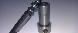
There is no doubt that when a load is applied to the engine, the injection pump must always provide the engine with the required amount of fuel. All in-line injection pumps have a separate plunger pair (plunger (3) and liner (1)), also called a discharge section (element), for each engine cylinder.
The plunger is moved in the direction of fuel supply by a cam shaft driven by the engine, and returns back under the action of a return spring. Since the stroke of the plunger cannot be changed, the amount of fuel pumped can only be adjusted by changing the effective (active) stroke of the plunger.
Rice. Regulator operation
The plungers are equipped with an inclined spiral cut (channel), so that the required effective stroke is selected by turning the plunger. The rotation is carried out using a control rack (5), which is engaged with the plunger and itself moves longitudinally with the help of a regulator. Rotation of the plunger moves the helix (notch) (4) to control when the feed ends (also known as release or opening of the sleeve) and the amount of feed. Feeding begins at the moment when the upper edge of the plunger closes the inlet hole (2) in the wall of the sleeve.
In the case of maximum flow (c), no discharge occurs until the maximum effective stroke of the plunger, in other words, with the maximum possible amount of fuel supplied. With partial feed (b), the release occurs earlier depending on the position of the plunger when turning. In the final position, which is required for zero feed (a), i.e. at the moment when the engine must be stopped, the longitudinal groove of the plunger is located directly opposite the inlet hole. This means that the discharge chamber above the plunger is connected to the fuel line during the entire stroke of the plunger, i.e. fuel is not supplied.
There are several different helix configurations.
In the case of a plunger with only a bottom spiral (notch), fuel delivery begins at the same point in the upward stroke of the plunger, while the end of delivery occurs earlier or later depending on the rotation of the plunger. When the plunger has an upper spiral (notch), the start of the feed may change. There are also plungers equipped with both upper and lower ones.
Finding dead spots
The starting positions for adjusting the diesel distribution elements are the upper and lower extreme positions of the movement parts, which are respectively called top or bottom dead centers.
Usually, special marks are applied to the flywheel rim mounted on the crankshaft, the combination of which with a special arrow-pointer attached to a stationary part of the diesel engine (flywheel housing, frame) corresponds to the installation of the crank arm of a given cylinder in the crankshaft. m.t.
On both sides of the mark, and sometimes along the entire rim of the flywheel, there are graduations to regulate gas, fuel, and air distribution.
To determine the upper and lower extreme positions of crosshead diesel engines, there are special marks on the slides and parallels, the combination of which indicates the extreme position of the movement parts of the desired cylinder, however, if the reliability of the installation of the movement parts at dead points is in doubt, there are several ways to install them in. m. t. and n. m.t. without special graduation and markings.
To determine c. m.t. for a crosshead diesel engine, turn the crankshaft in the direction of rotation and, without bringing the crank 20-30° to the e.g. m.t., cause risks (Fig. 168):
- anywhere on the slider;
- on parallels against the first mark;
- on the shaft anywhere;
- opposite the third mark on the bearing shell.
Then turn the crankshaft in the direction of rotation until the first mark coincides with mark 2 (position B) and apply mark 5 on the bearing shell opposite the moved mark 3 on the shaft.
Having measured the distance between marks 4 and 5, divide it in half and put mark 6 on the bearing shells. Rotating the crankshaft until marks 3 coincide with mark 6, install the movement parts in c. m.t.
To determine the dead points of a trunk engine, the injector is removed, a rod is inserted into the hole, which rests against the bottom of the piston and moves with it, acting as a slider, and instead of marking the parallels, a rigid pointer is installed on the cylinder cover. The rest of the determination of dead spots remains the same as for a crosshead diesel engine.
General description of fuel injection pump assembly
Before assembling the fuel injection pump, it is necessary to wash and troubleshoot it. It is advisable to wash fuel pump parts and injector bodies in drum-type washers operating in a closed cycle. For the last 5 months, the author has been using a Geyser sink with a drum diameter of 700 mm.
When troubleshooting parts of the injection pump and regulator, the author recommends replacing the following spare parts when the plunger pairs are worn:
- 2 418 455 727 – Plunger pair – 8 pcs.;
- 2 418 459 037 – Discharge valve – 8 pcs.;
- 2 414 612 005 – Valve spring – 8 pcs.;
- 2 410 422 013 – Rotating sleeve of the plunger (if there is wear on the ball, look through an 8x magnifying glass);
- 2 417 010 022 – Complete fuel injection pump repair kit;
- 2 427 010 049 – Repair kit for fuel injection pump regulator;
- 2 421 015 057 – Regulator gasket;
- 2 447 010 043 – Repair kit for high pressure fuel pump valves.
When troubleshooting, pay attention to the working surfaces of the cam shaft, pushers, bearings and springs. The injection pump housing must be cleaned; before washing, all rings remaining after dismantling the plunger bushings must be removed
Figure 1.1 shows the tools for installing the plunger and pusher and fixing the pusher.
Figure 1.1 – Tool kit for installing and fixing the plunger
The position of the pusher lock is such that the catalog number indicated on the pusher body is located on top, and the 0 mark on the rotating part of the lock is on the bottom. Install and dismantle the pusher stoppers on fully depressed cams in order to prevent breakage of the stoppers.
The cam shaft should be installed as shown in Figure 1.2.
Figure 1.2 – Position of the camshaft cams when installing and removing the pusher stops
Install the cam shaft as shown in Figure 1.3.
Figure 1.3 – Installation of the injection pump cam shaft
It should be noted that on the fuel injection pump shown in the photo, it is more convenient to dismantle and install the cam shaft from the regulator side. Many models use tapered bearings, so dismantling the cam shaft should be done through the front part of the injection pump after removing the front HF bearing cover.
Dismantling and installation of the cam shaft into the fuel injection pump housing is carried out using a press or with light blows through a copper or aluminum adapter.
It is recommended to carry out all impact work with rubber hammers.
Use metal plugs only once.
Adjustment procedure
The need to install injection arises when replacing a high-pressure fuel pump (HPF) or installing it after repair, as well as after repairing the piston group of a diesel engine. The adjustment is carried out provided that the fuel equipment, injection pump and the adjusted gas distribution mechanism of the diesel engine are in good working order. The installation process consists of the sequential operations described below.
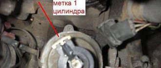
Installing the first cylinder on the compression stroke
On the right side, in the direction of travel of the machine, in the wall of the engine mounting to the clutch housing, above the longitudinal beam of the tractor frame near the oil filler neck, there is an installation dipstick. With its short threaded part it is screwed into the mounting wall and with its long threadless part it is installed outside. If it is necessary to install the first cylinder in the “compression” stroke position, the dipstick is installed in the hole, resting its long part against the engine flywheel. Slowly turning the diesel crankshaft, find a position in which the probe will fall into the hole on the flywheel and enter the body of the part completely by 4-5 cm. It is important not to confuse the installation hole with the technological, balancing drillings of the flywheel, which are much smaller in depth. The found position corresponds to an advance of 26 ̊ before the piston of the first or fourth cylinder approaches TDC. This position corresponds to the technical requirements of D 240 for setting the start of fuel injection into the cylinder during the “compression” stroke. To determine which of the cylinders in the first or fourth the “compression” stroke has begun, you need to remove the valve cover. A pair of closed valves will indicate in which of the two cylinders (first or fourth) the “compression” stroke has begun.
Installation probe for D 240
To change the position of cylinders 1 and 4 during the “compression” and “exhaust” strokes, you need to rotate the crankshaft 360 ̊ until the hole coincides with the dipstick again. In practice, it does not matter for which cylinder the injection timing is set to 1 or 4.
Disconnecting the pump drive
To establish synchronization of the engine and fuel injection pump operating cycles, you need to understand that the pump drive connecting through the engine timing gears must be disconnected. The drive is connected by connecting the holes of the pump drive gear 4 with the adjusting holes of a special washer 5 along the perimeter through a splined bushing fixed to the pump shaft. Access to the drive is achieved by opening the front cover 8 of the pump. To disconnect, unscrew two fastening bolts 3 with strip 7 and remove the adjusting washer from the splined sleeve. In this position, the rotation of the shaft cranks will not be transmitted through the camshaft gear drive to the pump shaft 6 .
Injection pump drive device D 240
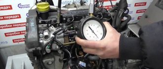
Momentoscope installation
After identifying the cylinder in the “compression” stroke and disconnecting the drive on the fuel pump, install a torque scope on the corresponding supply section of the pump instead of the high pressure pipeline connecting the section to the cylinder injector. To more accurately determine the beginning of the injection moment, set the manual fuel supply lever to the maximum position. To determine the moment of injection, if necessary, pump the fuel equipment with a manual pump pump, removing air from the system.
Injection installation operations
The momentoscope is a glass or plastic transparent tube, which is screwed onto the fitting of the fuel pump section with its threaded part.
Determining and setting the timing of fuel supply
By turning the injection pump camshaft clockwise and observing the fuel level in the device tube, you need to determine the position of the pump shaft at the moment fuel supply begins in this section. The moment the supply begins will be the position at which the fuel level in the device tube begins to rise, shifting as a result of the start of the supply cycle, running the injection pump shaft cam onto the plunger pusher of the corresponding section. It is very important to determine the beginning of this cycle by observing the fuel level in the momentoscope.
Injection pump drive with adjusting washer assembly Adjusting washer for the injection pump drive Splined sleeve in the injection pump drive Engine installation probe D 240
Experienced tractor drivers and repairmen establish the timing of fuel supply by observing the hole in the recess of the section fitting. The feeding moment is determined when the fitting recess begins to be filled with fuel.
Setting the position of the pump drive shim
Having determined the moment of the start of injection on the section by the position of the injection pump shaft, connect the pump drive by installing a splined adjusting washer on the splined bushing. The fastening bolts with the strip are screwed into the most aligned holes of the washer and the flange of the pump drive gear. In this case, the bolts should fit freely without snagging. Then install the pump cover by tightening the three bolts around the perimeter of the cover. The axial clearance of the drive gear is adjusted using the adjusting central screw in the cover. To do this, unscrew the lock nut of the screw, screw it all the way into the washer bar and unscrew it 1/3 or 1/2 turn, after which the position is fixed with a lock nut.
Attention! Before starting the diesel engine, do not forget to remove the installation probe from the flywheel and screw its short threaded part into the installation hole.
When it is necessary to adjust injection
At the factory there is a special machine for adjusting the injection pump. Therefore, it works well without adjustments. But, there are times when, after some repair work, you have to adjust the injection angle, for example:
- After replacing the timing belt
- You removed the fuel injection pump, and you cannot install its pulley according to the special marks.
- Any other unavoidable repair work that disrupts the injection angle adjustment.
Let me remind you, dear readers, that to fully adjust the fuel injection pump you need a special stand. Therefore, disassembling it into parts or turning all the screws on it is simply stupid. You will misadjust the device so much that later, without a stand, you will no longer be able to adjust the operation of the motor back. Therefore, if you don’t understand what and why to turn, do not touch the pump’s full load screw and other screws, because you will not be able to adjust them back. You don't need extra problems and expenses, do you?
Useful tips
The main recommendation before any work related to dismantling fuel equipment with your own hands is to apply and refresh marks on all gears, pulleys and other elements. Stripes are applied with paint or permanent marker. So that when assembling, combining them, it is easier to assemble the equipment and not disturb the ignition adjustment.
You can regulate the ignition on a diesel engine in the following ways:
- Adjustment by marks, if any.
- Selection of injection experimentally.
How to correctly set the fuel injection pump on a diesel engine
Hello everyone, the fuel injection pump is the heart of a diesel car. If the injection angle fails, the engine begins to smoke and knock. Today I’ll tell you how to adjust the injection angle of a fuel injection pump, because detonation knocks destroy the engine.
Smoking is also not a good sign; the fuel does not burn completely, releasing soot, which settles on engine parts and gets into the oil, gradually clogging the oil channels and forming plaque on the valves. This increases diesel consumption and reduces compression. You can adjust the injection angle yourself, avoiding problems and unnecessary costs.
Controlling the moment when fuel supply starts
The moment the fuel supply begins is regulated by a closed-loop electronic control system (feedback control system). An injector needle movement sensor installed in one of the injectors (usually in the first cylinder) sends a signal to the electronic control unit about the actual moment of fuel injection. This information is used to determine the actual injection start point in degrees of rotation of the engine crankshaft, which in turn can then be compared with the setting value of this value and subsequent adjustment is made according to the electrical signal sent to the fuel start actuator.
The actuator (drive) for starting fuel supply is “structurally rigid”. For this reason, you can dispense with a special feedback sensor. Structural rigidity means that the directions of action of the forces of the electromagnet and the spring always have a precisely defined point of intersection, that is, these forces are always in equilibrium. Thus, the linear movement of the electromagnet armature is proportional to the strength of the electric current, which is equivalent to the action of feedback in a closed-loop control system.
Ignition control
Electronic ignition control
How to set the ignition angle? On systems with electronic ignition control systems, this can be done using computer diagnostics that connect to the Electronic Control Unit (ECU) or the “brains” of the car. And there you can see how the engine operates in real time - what signals are received from the sensors, what engine speed, fuel consumption, injection timing, ignition timing and other input and output data.
Diesel engine: power system design
Basically, you don’t need to change anything during operation unless you change the firmware. That is, if the machine somehow began to work incorrectly, then most likely there could be several reasons:
- An incorrect signal is received from the sensors; in this case, you can replace the supposed faulty sensor with a replacement one that is known to be working, and see if the result changes.
- The voltage in the network is incorrect and, accordingly, the sensors give the wrong signal. The input signal to the sensor is 5V, if this indicator is different, the ECU will receive incorrect input data and the engine will not be able to operate normally.
- The ECU is faulty. Quite often it happens that after going through everything possible, it turns out that your brains have flown. But don’t worry, they are inexpensive at VAZ.
Therefore, as such, the ignition is not set on injection machines, it is already built into the system, but it is worth checking whether the marks are set correctly.
Adjusting the ignition marks on the VAZ-2110 injector
When the engine is running, there are some phases that must work synchronously, the camshaft must coincide with the crankshaft, and the timing of fuel injection and ignition must correlate with them. Let's look at all this using the example of the VAZ-2110.
How to set the ignition on a VAZ 2110 injector
If the car doesn't start, it shoots, sneezes and everything goes wrong - the marks are not set somewhere and you need to sort it out.
On any car, the timing marks must be set perfectly, only then it will work normally. On the VAZ-2110, the crankshaft mark is located on the flywheel. You need to look through the inspection window on the gearbox housing; you can see the flywheel through it. It’s better to illuminate it with a flashlight, because it’s so easy to see.
The marks must match exactly. But... This may not happen. The fact is that when disassembling the engine, the flywheel can be placed on the other side, and then no one will need these marks. Let's consider other methods of how to deal with such a situation. To be honest, I have never set the timing belt to a mark on the flywheel; I don’t like this method.
A similar mark is present on the front belt pulley. Two points must coincide - one on the toothed pulley, and the second on the oil pump. If they coincide, it means that the pistons are at TDC of the 1st and 4th cylinders, and the crankshaft is set to its original position. It remains to do the same with the camshaft.
On single-shaft heads VAZ-2114, 2108, 2110, it is necessary to combine the boss on the sprocket and the protrusion on the rear timing belt cover.
What is ignition timing and how to set it yourself
For twin-shaft 16-valve engines, which are found on the VAZ-2112, the diagram looks a little different, the marks on the sprockets of both camshafts should look clearly upward, there are corresponding marks on the back cover with which they should coincide.
If all the marks match, great, the timing belt is ideal. Now all that remains is to check whether the crankshaft sensor is set correctly.
The crankshaft position sensor on the VAZ-2110 is installed in the front part of the engine; it reads readings from the sprocket, which is mounted on the pulley. This asterisk is placed on the key. And there are a few things to check here.
Since the pulley is placed on a key, a situation is possible when this seat breaks and the pulley is installed at a different angle, slightly turned out. From here, an incorrect signal will be sent to the crankshaft sensor, earlier or later than expected, and accordingly, the ignition will occur at an unknown time. It will be necessary to align the broken pulley more precisely, or change it along with the key.
Another problem may be that the crankshaft position sensor may be located too far from the pulley sprocket (maybe the sensor is slightly non-standard, or incorrectly installed), in which case the signal will be received incorrectly.
These are, perhaps, all the reasons that lead to ignition failure on a VAZ.
It plays one of the leading roles in the engine control system. This technology is needed to ignite the mixture of air and gasoline in the engine. A flash of the mixture is achieved due to the work of a spark from a candle. If problems arise with this element, it must be changed promptly, since otherwise you will not be able to start the car.
Adjusting high pressure fuel pumps
Regulation of the injection pump must be carried out on special stands by highly qualified specialists. When adjusting the pump, use the bench injectors or injectors with which the pump was installed on the engine, marking the number of each injector in accordance with the cylinder. Before checking and adjusting the high-pressure pump, all injectors (if engine injectors are used) must be carefully checked and adjusted on a special stand in accordance with the specifications for the given type and model of injectors. After adjusting the pump, each injector should be installed on a cylinder corresponding to the pump section that was adjusted together with that injector.
The overall performance of the pump plunger pairs can be assessed using bench injectors adjusted to an injection start pressure 1.8…2 times higher than the nominal one. If in this case the pump provides supply, then the plunger pairs are in normal condition.
***
Cycle feed adjustment
The main adjustment of the fuel pump is to adjust the quantity and uniformity of the cyclic supply at nominal mode. To do this, the injection pump rail (or the dispenser for a single-plunger pump) is installed with a special screw in the nominal flow position. At the nominal rotation speed, the cyclic flow of all sections is measured, monitoring the fuel level in the measuring tubes for each section of the pump.
To control the amount of cyclic flow across pump sections, glass graduated test tubes are used, mounted on a test bench and connected to the outlet fitting of the section, or (in modern stands) on a display that visually displays the cyclic flow across sections of the fuel injection pump being tested. The cyclic flow must comply with the specifications for the pump and be adjusted for the specific engine model.
Deviation by sections (unevenness of supply) is allowed no more than 3...5%. Otherwise, for pumps of the 33 (KAMAZ) and 60 (ZIL) series, loosen the fastening of the section housing and turn it, moving the housing lock washer by one or two teeth. Some pumps (4UTNM, YAZDA, ChTZ) have special clamps for fastening sections, which, if necessary, loosen and correct the cyclic flow by turning the section body.
Adjusting the feed start angle
This angle is checked and adjusted on a bench.
In in-line pumps, a momentoscope is installed on the first section, and in V-shaped pumps of the 33 series - on the eighth section - a glass tube connected through a rubber pipe to a high-pressure fuel line (see figure). The rack is set to the nominal feed position and by manually rotating the pump shaft (by the injection advance clutch), the momentoscope tube is filled with fuel. By turning the shaft back and then slowly rotating it forward, determine the moment when the fuel surface (meniscus) in the momentoscope tube shakes. The rotation is stopped. In this case, the dial of the stand will show the angle to the axis of symmetry of the plunger drive cam. This angle must be within the specifications for that particular pump. So, for the eighth section of a series 33 pump (KAMAZ), this angle should be 42...43˚, and for the first section of 4UTNM pumps - 56˚.
After checking the first (or eighth) section, the torque scope is installed on the remaining sections according to the order of operation of the engine cylinders. The deviation of the injection advance angles by sections should not exceed 20′.
In order to adjust the advance angle of the start of flow in series 33 pumps (KAMAZ), the pusher heel is replaced, which is produced in 18 repair sizes. In pumps such as UTNM, TN, YAZDA, the plunger pusher screw is moved for these purposes. After adjusting the section, this screw is locked with a lock nut.
***
Academic disciplines
- Engineering graphics
- MDK.01.01. "Car design"
- General structure of the car
- car engine
- Car transmission
- Steering
- Brake system
- Suspension
- Wheels
- Body
- Car electrical equipment
- Basic car theory
- Basics of technical diagnostics
- Fundamentals of hydraulics and heat engineering
- Metrology and standardization
- Agreecultural machines. Agreecultural equipment
- Basics of agronomy
- Transportation of dangerous goods
- Materials Science
- Management
- Technical mechanics
- Tips for graduate student
Olympics and tests
- "Engineering graphics"
- "Technical Mechanics"
- "Engine and its systems"
- "Car chassis"
- "Car electrical equipment"
Checking injection timing on distribution-type pumps is more difficult.
It will require the already mentioned sensor, as well as locating pins depending on the type of engine. This operation, as well as checking the injection advance using the dynamic method using a special diesel stroboscope (Bosch, Sun, AVL, Time Track Stanodyne, Technotest, etc.), is more profitable to carry out by professionals at a service station.
The injection advance on distribution-type pumps is statically adjusted as follows. Rotating the crankshaft, set the piston of the first cylinder to TDC. Refer to the alignment marks, or use the alignment pin:
Remove the plug from the fuel pump, insert the sensor in its place in a special holder and proceed in accordance with the instructions. The sensor should show the specified amount of injection advance. If adjustment is necessary, loosen the pump and rotate it accordingly, then recheck the timing.
When making adjustments, do not touch the fastenings indicated by the arrows:
Checking the tightness of the nozzle needle, adjusting the needle opening pressure and spray quality.
The main malfunctions in the operation of injectors can be clogging of the nozzle holes, jamming of the injector, leakage of fuel as a result of a loose needle fit in the socket, leakage of fuel between the needle and its guide, cracks in the guide sleeve, and fuel getting into the cooling cavity.
To prevent malfunctions, it is necessary to periodically carry out preventive inspections, control checks and repairs of injectors; main activities: grinding the needle against the seat, cleaning the nozzle holes, checking the density of contacting surfaces, setting the needle opening pressure.
In all cases, the nozzle must be disassembled and washed in kerosene or diesel fuel.
Grinding of the needle along the socket is carried out using a thin lapping paste, followed by washing; If a deep belt appears on the needle, it must be removed on a grinding machine, followed by grinding into the seat.
Control of the nozzle density, as well as adjustment of the needle lifting pressure, is carried out using a special press (Fig. 170, c). The press consists of a single-plunger pump 2, a pressure tank 4, a pressure gauge 3, a tripod 5, a fuel collector 6. The pump is driven by lever 1. After grinding in the mating parts and assembly, the nozzle is installed in a tripod and connected to the single-plunger pump.
By tightening the injector spring to a pressure slightly higher than the needle lifting pressure, fill the tube and injector with fuel and create the pressure specified by the manufacturer's instructions.
The quality of lapping is determined by the condition of the nozzle: for high-quality lapping, the nozzle must be dry. If the gap between the needle and the needle holder has not reached critical values, then the pressure in the system will drop gradually, over the time specified in the instructions.
In case of a rapid drop in pressure, the needle holder along with the needle is replaced. Then they move on to adjusting the needle opening pressure, for which a pressure exceeding the opening pressure is again created in the system, then the nozzle spring tension is gradually reduced so that the needle rises at the required pressure.
Checking and adjusting the uniformity of power distribution among the cylinders
As a result of misadjustment of the fuel equipment and violation of the dosage of fuel supplied to the cylinders, as well as changes in the volume of the compression chamber and deterioration of the condition of the compression rings, the engine can create rated power due to underloading of some cylinders and overloading of others. This phenomenon can lead to serious malfunctions in overloaded cylinders; to the appearance of cracks in the cylinder cover, cylinder liner and piston; to intense carbon formation as a result of poor fuel combustion due to a decrease in the excess air ratio and wear of the cylinder-piston group.
Uneven distribution of load across the cylinders causes uneven wear of the crank and frame bearings and bending of the crankshaft line.
The simplest control over the distribution of load across the cylinders can be carried out by the temperature of the exhaust gases and the temperature of the cooling water leaving the back space of the cylinder, and by the temperatures of water or oil leaving the piston. A more accurate distribution of power among the cylinders can be determined by taking and processing indicator diagrams.
After processing the indicator diagrams and determining the average indicator pressure “pt” for individual cylinders, the indicator power of each cylinder is determined.
Permissible deviations in power distribution should not exceed the average value by more than 2.5%. If the deviations are higher than these values, it is necessary to adjust the fuel equipment, determine the height and volume of the compression chamber, the compression end pressure, and the condition of the cylinder compression rings. If one of the cylinders fails and it is impossible to eliminate the malfunction, the diesel engine can be operated on the remaining cylinders, but the diesel power must be reduced so that the parameters of individual cylinders do not exceed the nominal values.
Checking the density of plunger pairs
The degree of wear of the plunger pairs can be checked at constant pressure, for which the plunger pair is installed on a special stand (Fig. 170, a).
Having filled the sub-plunger space with fuel, load the plunger with a control weight and at the same time start the stopwatch. The fuel leakage time between the plunger and the bushing is compared with the recommended one: if the time is reduced below the permissible level, the plunger pair is replaced.
Testing at variable pressure is carried out on a stand (Fig. 170, b). By pumping pressure into the plunger pair to the value recommended by the construction plant, the time it drops by approximately 100-200 bar is recorded and compared with the control. If this time is unknown, it can be determined by testing a new plunger pair.
The fact that advanced fuel injection for diesel engines is very important does not need to be explained to anyone. Naturally, for each engine speed, a certain value of the advance angle will be optimal, for example, for idle speed 800 rpm is 3°, 1000 rpm is 4°, 1500 rpm is 5°, etc. . To achieve such a relationship, which, by the way, is not linear, there is a special mechanism in the injection pump housing. However, this is just a piston (sometimes in the literature it is called a timer), which moves inside the fuel injection pump under fuel pressure and, through a special driver, rotates a special washer with a wave profile to a particular angle. If the piston is pushed further, the washer wave will hit the plunger a little earlier, it will begin to move and begin supplying fuel to the injector earlier. In other words, the injection advance angle depends on the fuel pressure inside the injection pump housing and on the degree of wear of the wave profile of the washer. As a rule, there are no problems with fuel pressure. Well, unless the fuel filter gets clogged, the plunger of the pressure relief valve gets stuck open, or the blades of the supply pump (inside the fuel injection pump) sink.
Rice. 38. To fully check the pressure relief valve, it can be unscrewed from the injection pump. The plunger inside this pressure relief valve must not be stuck. Whether this is true or not can be checked by pressing the plunger with a match. Under the influence of your hand, the plunger should move easily, compressing the spring.
Rice. 39. It is not difficult to unscrew the pressure reducing valve on an already removed pump. It is more difficult to do the same without removing the injection pump.
All these problems occur quite rarely and are easy to calculate. You can easily and unambiguously assess the condition of the fuel filter if you switch the engine to external power, that is, place a plastic bottle with diesel fuel under the engine hood, and disconnect the fuel injection pump and return lines from their regular places and lower them into this bottle. After this, we start the engine and check its operation. You can even drive several kilometers. If nothing has changed in the behavior of the engine, then the fuel filter and everything located further to the fuel tank are working properly. By the way, if you add 30-50% of any motor oil to a bottle of fuel, the injection pump will be forced to supply thicker fuel (a mixture of diesel fuel and oil). And if there is some wear in the fuel injection pump (for example, plunger pairs), this wear will seem to affect it to a lesser extent, and engine performance will become better. For example, it is very difficult to start a hot engine. The reason for this is often an insufficient volume of fuel supplied due to wear of the main plunger pair. And if this defect (difficult starting) almost disappears with thick fuel, you can confidently remove the injection pump and replace its worn pair. Although in this case, everything in the injection pump usually needs to be changed, and it is easier to throw it away than to repair it and then adjust it. However, this has already been written about above.
The condition of the pressure relief valve (may be jammed) and the feed pump can be assessed using a manual fuel pump. If the engine performance changes after you start pumping with a hand pump while the engine is running, i.e. If you start to manually increase the pressure in the fuel injection pump housing, then either the valve or the pump is faulty. It is easy to unscrew the pressure reducing valve without removing the injection pump and check it. Only on most diesel engines, to do this, you have to remove the corner of the bracket with a thin chisel, after which the head of the pressure reducing valve becomes accessible to a special key. By the way, this pressure reducing valve can also be turned out using a long bit (chisel) without using a key.
Rice. 40. You can increase the pressure in the injection pump housing by pressing the plug (1) of the pressure reducing valve (2) with a thin beard. As a result of these impacts, the spring (3) will press harder on the plunger (4) and it will close the fuel discharge hole (5). To return the plug back (to reduce the pressure in the injection pump housing), you need to punch the plug downwards so that it compresses the spring completely and presses on the plunger so as to push out the stopper (6). After this, both the plunger and the spring easily fall out. Next, you need to turn the pressure-reducing valve over and use a thin beard to push the plug back through. Next, put everything back in place and try again to adjust the pressure.
There, all the seals are made on rubber rings (torics) and no strong tightening is required. If this valve is intact and its plunger is not stuck in the open position, then a malfunction of the feed pump should be suspected. Provided that when pumping fuel, engine operation becomes smoother. True, if fuel with air bubbles flows from the overflow (return) line when the engine is running, then first of all it is necessary to eliminate the air leak. Because if there is an air leak, it will be difficult to create the required pressure in the fuel injection pump, even with a fully operational feed pump. But problems with air leaks are a separate issue. Here we just note that air leaks, even with external power, i.e. when the fuel canister is located above the injection pump, it is possible through the injection pump seal and through the leakage of the central plug on the cast iron part of the injection pump. This plug is used to accurately set the fuel injection pump according to the angle of fuel supply (unscrew it, install a micrometer head and measure the stroke of the plunger, this procedure is described in almost all repair manuals for injection pumps). With a fully operational fuel injection pump, even if it was previously aired, after 10 minutes of engine operation there are no air bubbles in the overflow line.
So, the injection advance angle depends on the engine speed. To save fuel, achieve high power and in terms of the environment, it will be better if this advance angle changes taking into account other engine operating conditions, such as the amount of load on the engine, boost pressure, temperature, etc. But it is possible to fully take into account all these conditions only for fuel injection pumps with electronic control. For conventional mechanical ones, only the fuel pressure in the injection pump housing and, on more modern units, the temperature of the engine coolant are taken into account. The piston in the lower part of the fuel injection pump moves depending on the fuel pressure and, through a special steel “finger,” slightly rotates the profile washer (the same washer is forcibly rotated by the driver from the heating device mechanism). As a result, the wave protrusion of the washer will run into the plunger earlier, and it will begin its movement earlier. This entire system was calculated and made at the factory and, at the very least, coped with its responsibilities. Until intense wear and tear begins. It became intense because the injection pump began to receive fuel without lubrication (our “dry” winter fuel, like kerosene, contains almost no heavy fractions, which ensure the lubrication of all rubbing parts), fuel with air and simply dirty fuel ( with abrasive). However, ordinary old age also takes its toll. As a result, the protrusion on the washer begins to run a little later onto the plunger, and it, in turn, begins its movement a little later. In other words, a later injection begins. The beginning of this phenomenon looks like this. The engine idles and, due to varying wear of the injectors, shakes a little. We add speed to it. At about 1000 rpm the engine stops shaking and seems to freeze - it runs smoothly - smoothly. We are still increasing the speed. And suddenly, in the range of 1500 - 2000 rpm, shudders appear. These shudders (shaking) can appear both with a smooth, but intense, and with a slow increase in speed. When shaking, blue smoke comes out of the exhaust pipe. When the engine warms up completely, the shaking in the region of 1500 - 2000 rpm disappears. This is at the very beginning of the development of the defect. Then the shaking does not go away even after the engine warms up. Exactly the same shaking appears if you increase the injection pressure on the injectors. In this case, if the fuel injection pump is worn out, late fuel injection will also occur. We get rid of this phenomenon by turning the injection pump housing to an earlier injection. Sometimes you have to turn the injection pump almost all the way. But before you do this, listen to the engine. When a diesel engine has too early injection, it starts to work more harshly (they also say that its valves are knocking). And if you make sure that 50-100 revolutions before the start of shaking, this harsh component in the acoustic background of the diesel engine has disappeared, then you definitely need to turn the injection pump. It should be noted here that in worn-out diesel engines the piston-cylinder gap is very large and therefore they begin to work harshly even with the absolutely correct injection advance angle. Using a strobe light to set the injection advance in our case is not entirely justified. Let’s not talk about the fact that stroboscopes more confidently pick up with their microphone the knock of an already badly worn injector. If the injector is in good condition and the fuel supply tube is properly secured, the strobe lamp, as a rule, malfunctions. Using a stroboscope, you can set the injection advance at idle. It is this advance that is given in the technical documentation. But wear in the fuel injection pump is uneven. And very often, having set the advance according to the mark using a strobe light at idle speed, we do not get rid of shaking at speed caused by late fuel supply. That's why we recommend setting the lead by ear. Given the wear and tear that the diesel engines we operate have, this is a more acceptable method. After all, this is the only way to compensate for late injection caused by low fuel pressure in the injection pump housing due to wear of the supply pump. This is almost the same as adjusting the ignition timing for gasoline engines. You can use instruments to set the ignition timing only at idle speed (and the repair manuals do not suggest anything else), but due to a malfunction, for example, of a centrifugal regulator, the car will not drive. It is clear that it needs to be repaired or replaced. But you can, by turning the distributor, set an acceptable ignition timing by ear. The only difference is that for gasoline engines, the criterion for correctly setting the ignition timing without the use of instruments will be detonation knocks and engine power, and for diesel engines - shaking, smoke and knocking in the engine.
It was already mentioned above that most fuel injection pump problems occur due to all kinds of leaks and leaks. For example, a plunger has worn out, a leak has occurred, and so it does not create pressure. What if I replace the fuel with a thicker one? Then the increased gaps in the mating parts will seem to become smaller. And the fuel injection pump will work as if it had no wear at all. Making fuel thick is very easy. Add, as mentioned above, any motor oil to it. Of course, you don’t want to drive like this - the fuel is too expensive (and it’s troublesome, constantly preparing thick fuel). But for checking the condition of the fuel injection pump (as well as for successfully selling a heavily used car at the market), this technique is useful. In the cold season, due to natural laziness, in order to make the fuel thicker, we simply cool the injection pump. For example, a car with a diesel engine comes in with a complaint that it is difficult to start if it sits for five minutes, but the engine is still hot. We start this car (indeed, sometimes we have to turn the starter for 30 seconds), warm it up for another 10 minutes and turn it off. After that, we open the hood and cool the injection pump with snow. Within the same 5 minutes. If after this operation the engine starts better than the first time, we can already talk about severe wear of the fuel injection pump. Of course, both of these tricks (with thick fuel and with cooling the injection pump) are not described in the factory engine repair manuals and therefore cannot be considered very scientific. Those manuals measure the volume of fuel supply at startup (there is such a parameter in the technical data - the volume of supply at a rotation speed of 200 rpm) and checking this parameter at home is also easy. To do this, you need to unscrew all the glow plugs and remove the tube from one injector. Then put the body of a disposable medical syringe on this tube and turn the engine with the starter. Naturally, counting the “zilch”. 200 “zilch” is, of course, a lot. 50 is enough, and then compare the result with the technical data. In this case, we can assume that the injection volume at 200 rpm for all Japanese diesel engines, if they have the same volume, will be the same. If the volume of your engine is slightly different, it is easy to make a proportion with the volume of the diesel engine for which you have data. We also do all this when a hot engine does not start well, although, as follows from practice, everything can be checked in a simpler way. Using snow and motor oil. In other words, if the operation of the injection pump with thick fuel becomes more acceptable, the injection volume must be checked. It’s better, of course, to do all this at a stand (there you can check all operating modes of the fuel injection pump), but in the start mode (i.e. at 200 rpm) the check can be done in the garage.
So, if a diesel engine has shaking in the region of 1500 - 2000 rpm, accompanied by blue exhaust gases, the fuel system must be repaired. And in particular, do fuel injection earlier. To do this, in the simplest case, you need to turn the injection pump to an earlier injection.
Kornienko Sergey
© Legion-Avtodata
Diagnostician Vladivostok