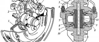
Single disc clutch device
The clutch housing 8, usually cast from cast iron, is usually an intermediate part between the engine and the gearbox, and houses the clutch.
The crankcase has holes for installing the fork shaft 15 of the clutch release mechanism, for ventilation of the clutch (which is necessary for better removal of heat generated when the discs slip), and for access to the adjustment devices of the release levers. Adjusting devices are designed to set the inner ends of the lever in the same plane to avoid distortion of the pressure plate. The crankcase 8, through a gasket 28 and a rubberized flap 29, is closed with a cover 21, in which a plug 24 with a cotter pin and an oil sump flap 25 are installed.
The clutch casing, stamped from sheet steel, is equipped with stiffeners and ventilation holes, and also has recesses to hold the springs 7 from being thrown out under the influence of centrifugal forces. The holes in the casing for fastening the forks 18 and fingers 20 of the release levers 16 in some clutch designs are processed into a sphere to mate with the corresponding sphere of the adjusting nut 17. The casing is secured with its flange by bolts 6 and 23 to the flywheel 2 connected to the crankshaft 1 of the engine. The flywheel and pressure plate 3, which are the driving part of the clutch, are usually made of cast iron and have a carefully machined end surface in contact with the friction surface of the driven disk 26.
The opposite side of the pressure plate has ribs to reduce its warping and better heat removal, lugs for connection with the outer ends of the switching levers, which are usually mounted on the axles using needle bearings 22, which reduces friction losses in the switching mechanism. On the same side of the pressure plate there are bosses on which the peripheral clutch pressure springs are installed. The thickness of the pressure plate must provide a certain heat capacity of the disk to avoid overheating during short-term clutch slipping. Along the outer circumference of the disk there are devices that create a tangential connection with the clutch housing, but allow axial movement when the clutch is engaged and disengaged. These devices in different clutches can have different designs: elastic tangential plates 4 with bushings 5; grooves and projections in the casing and on the disk, respectively; fingers fixed in the casing and flywheel and passed through holes in the disk.
The housing assembly with pressure plate, levers and springs is carefully balanced.
The release levers (stamped steel) are made rigid if the driven disk is equipped with devices that reduce the sharpness of clutch engagement, or elastic (for example, in the form of a diaphragm central spring) when such devices are not provided. Friction losses in the switching mechanism are minimal when both swing axes of each switch lever are mounted on needle bearings. In this case, the swing axis of the lever, installed in the casing fork, can move relative to the casing when turning the lever due to the elastic support plate 19 and the spherical surfaces of the nut on the fork 18 and the socket in the casing hole.
Rice. Single-plate clutch device: 1 - crankshaft; 2 - flywheel; 3 — pressure disk; 4 - elastic plate; 5 — bushing of spring plates; 6 — plate fastening bolt; 7 — pressure spring; 8 — clutch housing; 9 — clutch casing; 10 — heat-insulating gasket of the pressure spring; 11 — clutch release bearing; 12 — bearing coupling; 13 — clutch release spring; 14 — coupling guide; 15 — clutch release fork; 16 — clutch release lever; 17 — fork adjusting nut; 18 — fork; 19 — support plate of the adjusting nut; 20 - fingers; 21 — clutch housing cover; 22 — needle bearings; 23 — bolt securing the clutch housing to the flywheel; 24 — plug with cotter pin; 25 — oil collector shield; 26 — clutch driven disc; 27 — oiler for lubricating the front bearing of the gearbox drive shaft; 28 — gasket; 29 — shield; 30 — gearbox drive shaft; 31 — front bearing of the gearbox drive shaft; 32 — oiler for lubricating the clutch release fork; 33 — flange gasket; 34 - sealing ring
In some cases, the brackets for the swing axes of the switching levers are rigidly attached to the casing. Then, to ensure rotation of the levers, instead of a needle bearing in the fork, two cylindrical rollers are installed along the swing axis; sometimes one of them has a longitudinal flat. These rollers, rolling over one another, provide some displacement of the swing axis when the lever is turned. Adjustment of the position of the inner ends of the release levers in one plane perpendicular to the axis of rotation is carried out either by nuts with a spherical surface, or (in their absence) by special adjusting screws with spherical heads, which come into contact with the end surface of the clutch 12 of the release bearing when the clutch is released. In the adjusted position, the nut and screws are securely fixed by locking devices. In various clutch designs, the number of release levers ranges from 3 to 20.
Clutch springs are made of high quality spring steel and heat treated. The springs, in a partially compressed state, are installed between the housing and the clutch pressure plate, ensuring that the rubbing surfaces of the driving and driven parts of the clutch are pressed in the engaged state. When the clutch is disengaged, when the springs are maximally compressed, their force increases by 15...20%. In permanently closed clutches, the force of the pressure springs in the on, and in some designs, in the off state is closed inside the clutch and is not transmitted to the shaft bearings. Under each spring, on the side of the pressure plate, a heat-insulating gasket 10 is placed to protect the springs from heating and deterioration of their elastic properties when the pressure plate is strongly heated during clutch slipping.
The driven disk 26 of the clutch through the hub transmits, when the clutch is engaged, the engine torque to the drive shaft 30 of the gearbox. To increase the friction force, ring linings made of friction material with a high friction coefficient are attached to the driven disk on both sides. The disc is connected to the hub with rivets or through parts of the torsional vibration damper. Typically the driven disc has radial slots to reduce warping.
The design and principle of operation of the clutch
Everyone probably knows about such a car component as the clutch. And many people know that it is needed to be able to safely change gears even when the car starts moving. But how does the clutch work, this rather capricious unit to master in a driving school?
Earlier, in the article “Car Clutch,” we talked about the purpose and classification of clutches. Now let's take a closer look at the design and operating principle of the most common type of clutch - a dry friction single-plate clutch.
Dry friction clutch device
A dry friction clutch consists of the following main parts:
— Flywheel; — Pressure plate (clutch basket); — Driven disc (clutch disc); — Release bearing (clutch release bearing) and push clutch; — Clutch drive parts.
Flywheel. The flywheel is mounted directly on the engine crankshaft and it is through it that torque is transmitted to the transmission. Today, dual-mass flywheels are usually used: one part is mounted on the crankshaft, and the second plays the role of the clutch drive disc - friction linings are attached to it, which ensures rotation of the driven disc. The flywheel parts are connected through springs, which act as dampers that reduce vibration levels.
Pressure disk (“basket”). This unit consists of a housing (which is shaped like a basket, which is why it got its name) and a pressure plate directly connected to the housing through a spring (or springs). Springs constantly press the pressure plate against the driven disk, due to which torque is transmitted from the engine to the gearbox. The “basket” can use several springs arranged in a circle, but now more often a single spring (diaphragm) is used, consisting of a number of tangential (radially located) plates. On one side the plates are connected to the housing, and in the center - to the release bearing. The basket is rigidly fixed to the flywheel, rotating with it as a single unit.
Driven disk. Located between the flywheel and the pressure plate, its hub is mounted on the input shaft of the gearbox. The disk has a prefabricated design: its basis is a metal disk, on which there are friction linings on both sides. The disc also has damping springs that soften impacts and make torque transmission smoother.
Release bearing and clutch. This is a specially designed bearing that rests against the central part of the diaphragm spring and compresses it when the clutch is depressed. The throwout bearing is necessary here for a simple reason: the basket rotates with the flywheel, and if there were no bearing, the throwout clutch would be subject to severe wear. The presence of a bearing solves this problem, since the clutch presses on its outer part, which does not rotate, and the force on the spring is transmitted through the inner ring.
Clutch drive parts. These are the components for engaging and disengaging the clutch. This includes the clutch release fork (with its help the pressure clutch moves), cables (mechanical drive), hydraulic cylinders and tubes (hydraulic drive), pedal, etc.
ADVANTAGES OF SINGLE DISC CLUTCH:
• Simple design and reliable operation; • Low price compared to other options; • Possibility of converting machines with a double-disc clutch with the additional replacement of only the flywheel and changing the drive control.
Design and operation of a single-plate clutch
This option consists of 3 elements that work together as a clutch kit:
A single-disc clutch performs a number of important functions, the main purpose of which is: 1. To smoothly start the vehicle; 2. Reliable transmission of torque from the gearbox to the internal combustion engine (ICE); 3. To ensure complete connection/disconnection of the motor and transmission when changing speed modes while driving.
If a single-plate friction clutch is found to be faulty or broken, it is necessary to at least understand the cause. This may be due to the failure of interconnected parts and components of the machine. In any case, before changing a single-plate clutch, diagnose the vehicle, and also ask the service station technician to visually inspect the removed parts. Characteristic marks and abrasions of the friction lining or wear of the diaphragm springs of the clutch basket will help you understand what exactly is the cause of the malfunction.
This approach will save money. After all, if it turns out that the cause of the breakdown is not related to the single-plate clutch kit and it is in good condition, then there is no need to change it.
In addition, although it does not entirely comply with the manufacturers’ recommendations, you can understand which of the clutch elements has worn out and buy only the failed disc or bearing. But there is an important nuance - when replacing only one spare part of a KAMAZ or MAZ clutch kit, you must buy a part from the manufacturer whose elements you are leaving behind!
For example: you leave the basket and clutch with Sachs, then the driven disk must be of this particular brand, owned by the German concern ZF.
If you have problems with a single-plate friction clutch, you need advice or an independent expert opinion - contact GAS Quatro LLC!
Working principle of friction clutch
The operation of a dry single-plate friction clutch is very simple and boils down to the following. The clutch is always engaged - this is ensured by a diaphragm spring (or series of springs) that presses the pressure plate against the driven plate and the flywheel. In this position, the entire clutch assembly rotates as a single unit, and the torque is completely transmitted to the gearbox.
When changing gears, the clutch is disengaged: when you press the pedal, the spring is compressed (using the clutch drive, pressure fork, clutch and release bearing), its plates, fixed in the “basket,” act as levers and move the pressure plate away from the driven disk. At this moment, the transmission of torque from the engine to the box stops and you can change gear.
After engaging the desired gear, the clutch pedal is released, the spring returns to its original position, pressing the pressure plate against the drive plate and the flywheel - torque transmission resumes.
However, the main advantage and all the possibilities of traction appear at the moment the car starts to move. The clutch is designed in such a way that the discs can be pressed against each other with different forces, and therefore torque can be transmitted to the extent necessary. If you slightly release the clutch pedal, the discs will be pressed weakly against each other and slip, accordingly, and the torque will not be fully transmitted to the box and wheels - this makes it possible to start and smoothly accelerate the car.
How do all the components work together?
Let's assume that at this very moment you get into your car and hit the road. When you want to change gear, you (as you should) press the pedal to do so. By pushing it, you are actually pushing the pressure fork, which in turn pushes the release bearing, pushing it towards the diaphragm spring.