Gazelle gearbox repair is a complex undertaking that needs to be prepared for in advance. The gearbox operates by transmitting torque to the wheels from the motor shaft. It is worth understanding that the slightest malfunction in the functioning of the transfer case can threaten your safety. If there is no service station nearby, you can repair the fault yourself. If you strictly follow the step-by-step instructions, even a novice motorist can carry out this procedure without any problems.
What are the faults of the Gazelle gearbox?
Gazelle gearboxes are rightfully considered one of the most reliable and durable, but even they can become unusable due to high loads. In order for the replacement of the Gazelle gearbox to go without a hitch, you must know the hardware of the car, study the diagrams, be careful and patient, and also follow the safety rules and understand the principle of operation of the Gazelle 4x4 gearbox.
Gazelle repair may be required in some cases:
- difficulty changing gears. This snag occurs due to the lack of fluid in the cylinder or due to the presence of air in the hydraulic drive. In addition, you can check the locking bolts, which often need additional tightening, as well as the transmission intermediate shaft. You can observe how the device jerks in neutral, and the transmission howls. Another sign is that in 4th gear, fifth or second, the device makes a howl, a lot of noise;
- The gearbox engages with noise and crackling noise when starting. In this case, the synchronizer blocking ring on the transfer case could be worn out or deformed. Also check the power take-off. It is advisable to replace the blocking ring or power take-off box, and to ensure that the new element fits in without problems, use lapping paste. In addition, check the condition of the input shaft, how the mortar works, whether the car is noisy in neutral;
- random shutdown of the manual transmission. If you notice such a problem, first of all check the fastening nuts to the clutch housing, as well as the condition of the gazelle gearbox linkage. In addition, the couplings could wear out (worn out teeth), as well as the locking springs (they can either wear out or weaken). You may also need to adjust the intermediate shaft and input shaft;
- the appearance of extraneous noise. In order to get rid of them, it is necessary to replace bearings or damaged gears, add oil to the crankcase or check its alignment with the crankshaft.
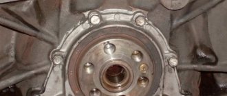
To repair a Gazelle gearbox, you must know everything about the structure of the transfer case, because disassembling the gearbox is not an easy task. This is also necessary to determine the type of failure. The most popular reason for Gazelle owners to replace the gearbox is oil leakage. It occurs due to worn out seals or bushings, worn out gaskets, as well as poor sealing of the plugs. In this case, you will need to add or change the oil in your car, as well as replace the bushing.
How to repair a Gazelle gearbox
The comparative cheapness, coupled with the spaciousness of this car, classified as a commercial vehicle, made it a real “workhorse”. It is in demand and is used throughout the CIS. Another sign of a classic work machine is the ease of finding spare parts. When you need to repair a Gazelle gearbox, and the gearbox is the worst of the components of this Russian light-duty car, you can safely go through everything, from bearings to synchronizers. These parts are available for sale at any auto store.
How to replace a gearbox on a Gazelle
How to remove the box? Replacement of the gearbox is carried out on an overpass or inspection pit. First, drain the oil from the crankcase. Now we remove the cardan. To do this, arm yourself with a file and put a notch on the connecting unit and the continuation of the gearbox on the gazelle. Now remove the support fasteners using keys thirteen and twelve. Using keys seventeen and fourteen, remove the fixation of the cardan to the flange of the main gear gear. We remove the shank and insert a rag into the hole. Now we need to get the lever to install the gearbox. To do this, we get rid of the cover and the top of the lever inside the cabin, unclench the bushing, remove the rubber cushion, floor seal and cover, cap and the lever itself.
Gearbox design on Gazelles Next
In 2013 Russia saw the new Gazelle Next. The developers of this model focused on the car's cabin. Everything for the comfort of the driver and passengers. But it was not taken into account that cars such as Gazelle Next drive long distances. And for this you need not only comfort in the cabin, comfortable seats, but also order under the hood of the car. The factory installed a 5-speed Gazelle Next gearbox. The new manual transmission has an assembly with parts from different manufacturers. When passing 40 thousand, switching speed from 2 to 3 or from 4 to 5, the driver begins to hear noise, crackling and other strange sounds. To determine what kind of sound it is, you need to have at least a superficial idea of what it is?
This is what Gazelle-Next looks like
Manual transmission mechanism
A 5-speed gearbox is a gear reducer that transmits torque from the engine to the wheels. The new gearbox has:
- 2 craters connected by bolts;
- primary, intermediate, secondary shaft. The first and second mechanisms are connected to the cardan and crankshaft.
Appearance of manual transmission on Gazelle NEXT
The intermediate shaft has teeth for first and reverse gears, as well as a gear block and a speedometer drive:
- synchronizers;
- speed fastening components;
- single gear activation blocker;
- device for damping vibrations.
Watch the video: Repairing the gearbox on Gazelle Next.
In 2021, while improving the Gazelle Next, the developers slightly changed the gearbox design:
- changing the width of the gear rims;
- installed the intermediate plate of the second and intermediate shaft;
- bearings were supplied of improved quality for increased load capacity;
- flange contact of cardan transmission.
- Synchronizers from Hoerbiger.
- Joystick handle.
This is what the Gazelle Next gearbox looks like
The designer also strengthened the rear axle for load capacity, and with all this there is a Chinese diesel power unit.
This modernization gave a positive result - high reliability, increased service life, torque transmission of 330 Nm.
External view of the Gazelle Next power plant
During the first inspection of the car, experts give recommendations on how best to run the car and at what speed the speed should be changed. Many car enthusiasts do not pay attention to this fact, since everyone considers themselves professionals. As a result, a problem occurs with the box - it makes noise, knocks, and behaves incorrectly.
Internal structure of the gearbox
The gearbox device is housed in a metal protective casing. The housing can be removed by twisting several fasteners around the perimeter of the assembly according to the user manual.
Gazelle gearbox diagram
When using a lever, one of the shafts is connected to the working system, while the others are disconnected from it.
It is not possible to select multiple speed modes at the same time due to the locking and adjustment systems. The gears don’t just “fly off” until one of the elements of the block system breaks. Torque from the engine is supplied to the transmission input shaft, then transmitted to the secondary shaft, and from there to the rear axle gas 3309.
Names of structural elements of the Gazelle 3309 gearbox
Breaking
If the manual transmission is noisy, there are reasons for this:
- the bearings performed their functions to the end;
- lack of oil.
The second problem is much easier to solve than the first. Check the amount of oil and “add” it.
We advise you to watch: how to repair a manual transmission on Gezali.
The first option requires replacement of spare parts. This is done either in a service center by specialists (if the car is under warranty, this is a big plus for the owner), or manually (but not by yourself). Only a person who knows the business can disassemble and assemble the checkpoint. This procedure requires knowledge, patience and perseverance.
So, the first thing to do is drain the oil. After this, remove the cardan. Mark the hinge points and the box extension, remove the clamp. Unscrew the cardan mount and remove the shank (move it back and pull it out). The result will be a niche. Next, remove all the necessary parts in the cabin, turn off the speedometer and light elements. After these steps, the box is removed and disconnected.
Gearbox design for Gazelle Next
In order to begin disassembling the gearbox, it needs to be made clean (washed thoroughly). Disassembly is carried out step by step only by a knowledgeable person. At the slightest mistake, the gearbox may not work correctly on the Gazelle Next or, in general, show no signs of life. After disassembling the box into parts, they should also be washed from traces of oil.
The cause of the strange sound is being found. It could be:
- wear of the secondary shaft bearing.
- Bearing play.
- Bearing idling.
Watch the video: how to replace the rear axle gearbox.
Other problems with component parts may also occur. Worn and broken components are replaced with new ones.
Possible problems with the Gazelle gearbox
Disassembling and repairing a gearbox (5-speed), regardless of the make and model of a Gazelle car, is always a crucial moment, anticipating serious work. Owners of commercial vehicles encounter this problem most often, so they have replaced it more than once. But is it worth it, having seen an advertisement on the Internet for repair of a Gazelle gearbox, to run there, jingling your wallet? Not necessary. It is quite possible to get by with an assistant, diagrams of the gearbox design and instructions for the necessary work. This is enough to repair or replace worn parts yourself.
The presence of a huge experience base on problems with the Gazelle box allows you to almost accurately draw up a “problem-cause” diagram.
Most often, the problem list looks like this:
- If during operation you hear a dull hum from the side of the box, this is a sure symptom of loosening of the fixing fasteners. Also, such a sound can signal the death of the most worn parts;
- The characteristic “crunching” sound is most often produced by worn-out bearings. In general, to avoid such a problem, it is recommended to replace bearings after 90 - 100 thousand km. On your own, or as planned at a service – it’s up to you to decide what’s convenient for you
- If gear shifting is accompanied by an unpleasant crackling noise, then it makes sense to think about replacing the synchronizer rings;
- There can be many reasons for difficult gear shifting. Perhaps the box drive itself is jammed or jammed. But there may also be wear of a certain group of parts (gears, burrs, etc.). Only a bulkhead will tell you the exact reason.
- Oil leak. According to statistics, this is the most common problem that is addressed to workshops. As in the case of oil loss in the engine, the main culprit here is hardened or, on the contrary, worn out gaskets and seals. But it may turn out that much more serious cracks in the crankcases are to blame.
Gearbox repair for GAZ 3302, GAZ 2705
The gearbox is a component of the transmission . It changes the gear ratio and torque transmitted from the engine to the vehicle's drive wheels. The gearbox has a very impressive service life and is capable of functioning flawlessly throughout the entire life of the vehicle. But this requires timely and high-quality checkpoint maintenance.
Today we will disassemble the gearbox of a Gazelle car. Let's add oil. To do this you will need a 12mm hexagon. If chips are found on the plug, it means there is wear in the gearbox.
The manufacturer recommends filling 1.2 liters. oil into the gearbox, but we recommend pouring at least 1.5 liters to avoid “oil starvation” in fifth gear during overload.
We disassemble the gearbox. For convenience, clamp it in a vice with the shank down, at an angle.
Dismantling the box
The gearbox is one of those parts of the car whose repair begins with complete removal. For newcomers to the automotive business, the task may seem titanically difficult, but this is not entirely true. It is enough to thoroughly study the diagram of the box itself (in this case, the gazelle gearbox, consisting of 5 steps) and its connections with the rest of the vehicle in order to understand how to remove it. So, let's begin.
Stages of removing the gearbox from a Gazelle:
- First of all, you need to drain the oil from the crankcase.
- Next comes the dismantling of the driveshaft. There is one nuance here: before starting removal, you MUST mark with a file or other tool the locations and directions of the location of the hinge and the box extension. And in general all commutations (rear axle and flanges). Then, we proceed to removing the intermediate support fasteners. You can purchase the set of tools required for this yourself, or they can be included in the standard gearbox repair kit. Next you need to separate the shaft from the main gear flange. Left a little. You need to remove the shank of the box. To do this, you need to slightly pull it back and carefully pull it out. The resulting hole needs to be plugged with some rags or unnecessary old clothes.
- We take out the gear shift lever. Everything is simple here - remove the cover and the top of the lever from the cab, unlock the bushing and remove the rubber cushion along with the second bushing. All that remains is to remove the seal with the cover and, turning out the cap, remove the lever itself
- It remains to disconnect the remaining elements from the gearbox - the speedometer and the light switch (reverse). Now you can remove the box itself. To do this, you need to unscrew the receiving pipes and the bracket to the box using the appropriate fasteners. Then we separate our gearbox from the clutch housing by removing the necessary fasteners. But now we will need a medium block of wood, or a small log - this is needed to protect the block head. Now, having removed the transverse fastening, we remove the box itself. Given the significant weight, it is advisable to prepare in advance.
Transmission bulkhead
To make repairs and replace parts, you need to know how to disassemble the Gazelle box itself. Yes, you will have to disassemble it anyway.
There is a chain of actions here:
- bearing cover – rear input axis (bushing) – breather – crankcase separation – fastening the gear shift fork (after putting the car in reverse mode) – lever body and gasket – clamp fittings – switch rods (order – 1, 2, 5, rear, 3, 4) – reverse axle and remove the rear shaft bearing retainer ring – remove the shafts themselves.
The diagram may seem complicated, but if you look at the box in person, everything will become clear. This is what self-removal or replacement of the Gazelle gearbox looks like.
Installation of the entire system is carried out in reverse order. The main thing is to remember to carefully lay out the removed parts so that you don’t get confused during the reverse process.
Disassembling the Gazelle Next gearbox
The gearbox must be disassembled in the following order:
— remove the clutch with the release bearing from the input shaft bearing cover;
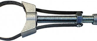
— fix the flange at the secondary shaft, loosen nut 50 and loosen (see figure below) the fastening of the flange at the secondary shaft, but do not remove the flange;
— remove the reverse switch 69 together with the gasket; remove plunger 67 (L=l 5 mm);
— Unscrew speed sensor 51; For ease of disassembly, you can install the box in a device for disassembling and assembling it (see figure below) and secure the box to the plate, placing the input shaft towards the top;
— Unscrew the bolts of cover 1 (see Fig. 3.31 above) at the input shaft bearing and remove it;
— remove retaining ring 81 from the input shaft bearing;
— unscrew the 4 bolts holding the front and rear parts of the plate box together;
— remove the front part of the gearbox housing (see figure below), holding the plate and the rear part of the crankcase. When separating parts of the housing, do not strike the end of the input shaft, this will lead to damage to the synchronizer;
— knock out the cage 71 (see Fig. 3.31 above) of the intermediate shaft bearing from the socket in the front part of the housing and remove the adjusting ring 72;
— unscrew the filling plug and breather from the front part of the housing;
— Unscrew the bolts that secure the gear shift forks 94;
— Unscrew the bolts and remove the housing 43 of the lever.
Unnecessarily, do not remove the pins in the neck of the lever housing and in the left wall, as well as fuses and springs. If the fuses jam and are difficult to rotate under the action of the springs, then it is necessary to knock out the plugs, remove the springs and fuses from the housing.
— place the box in a horizontal position;
— Unscrew the fastening bolts and disconnect plate 20 (see Fig. 3.31 above) of the clamps and the gasket;
— remove three fingers 22, three balls 24 and three springs 23 of the gear shift rod clamp;
— remove the 1st and 2nd gear shift rod 82 in place with the head;
- remove the fork with breadcrumbs;
— Unscrew the locking bolt and remove the 1st-2nd gear switch head from the rod;
— pull out the 3rd and 4th gear shift rod 90 together with the locking pin;
- remove the fork with breadcrumbs;
— remove the locking pin of the rod 89 for engaging 3rd and 4th gears;
— Unscrew the bolt 53 securing the reverse gear axis on the left side of the rear part of the housing;
— Unscrew the bolt and remove the head 83, the locking sleeve 86, and the locking sleeve spring 87 from the reverse and 5th gear engagement rod 85;
— unscrew the nut and remove flange 48 in place of the washer;
— holding plate 65, remove the rear part of the housing;
— knock out the outer race of bearing 37 from the socket in the rear part of the housing and remove the adjusting ring 55. Unscrew the drain plug from the back of the housing and (remove cuff 47;
— Unscrew the bolt securing the reverse and fifth gear shift fork;
— pull out the reverse gear and fifth gear engagement rod, remove the fork with crackers;
— remove the locking plungers 88 from the plates;
— remove rotor 45 from the secondary shaft of the speed sensor and ring 44;
— install a stop to support the input shaft and intermediate shaft in the assembly device (see figure below).
— place the gearbox in a vertical position with the input shaft looking down;
— remove the retaining ring 56 (see Fig. 3.31) of the intermediate shaft bearing 57;
— install the synchronizer clutch 33 of the fifth gear and reverse gear into engagement with the ring gear of the fifth gear synchronizer; fifth gear should be engaged, install the puller on the secondary shaft, secure the puller legs to the grooves of the synchro clutch. fifth gear and reverse gear of the secondary shaft;
— install another puller on the intermediate shaft, while securing its claws to the end of the ring gear of the fifth gear of the intermediate shaft;
— by turning the puller screws one by one, pull out the fifth gear with synchronizer coupling 33, with ring 8, washer 36 and inner ring of bearing 37 and fifth gear gear 58 with intermediate shaft bearing 57;
— remove the needle bearing 35 from the secondary shaft and replace it, install its place during assembly;
— remove two spacer bushings 7 from the secondary shaft;
— remove the locking ring 8 from the fifth gear gear, put a mark on the locking ring to put it in place during assembly;
— remove the retaining ring 32 of the secondary shaft of the synchronizing hub of the fifth gear and reverse gear;
— remove axle 60 assembled with the reverse gear;
— remove the reverse gear 59 from the intermediate shaft;
— remove the hub and clutch 33 of the 5th gear and reverse gear with nuts and springs from the secondary shaft;
— check the alignment of the marks on the engagement clutch and the hub; if they are missing, apply them to install correctly in place of the part during assembly;
— remove the fifth gear and reverse gear clutch from the hub;
— remove three synchronizer locks;
— remove the two synchronizer springs from the hub;
— remove the reverse gear with the locking ring from the secondary shaft;
— remove the locking ring from the reverse gear, put a mark on the locking ring in order to install it in its original place during assembly;
- pull out the needle bearing and put a mark on it so that it is installed in its original place during reassembly;
— the box must be installed in a horizontal position;
— secure the stop (see figure below) to fix the secondary shaft in the assembly fixture;
— install the gearbox in a vertical position so that the input shaft faces upward;
— remove the stop (Fig. 3.34) that holds the input shaft and intermediate shaft;
— turning the intermediate shaft to the side, remove the input shaft together with the blocking ring and rollers 78 from the secondary shaft;
Disassemble the secondary shaft, if necessary, tilting the intermediate shaft to the side;
— remove ring 77 from the third and fourth gear hub;
— remove the hub together with the 3rd and 4th gear clutch assemblies, synchronizer springs and cotters from the secondary shaft;
— check the alignment of the marks on the clutch and hub for the third and fourth gears and, if the marks are missing, they must be applied in order to install the parts in place during assembly;
— remove the 3rd and 4th gear clutch from the hub;
— remove three synchronizer locks;
— remove the two synchronizers from the spring hub;
— remove the third gear gear with the locking ring, bearing and spacers;
— remove the locking ring from the third gear gear, put marks on the ring to put it in place during assembly;
- remove the bearing and mark it to install it in its original place;
— pull out the retaining ring 11 of the secondary shaft;
— remove two pieces of thrust half-rings 12;
— pull out ball 25;
— remove the second gear gear with the bearing and all synchronizer rings, put a mark on the blocking rings to ensure correct installation during assembly;
- pull out the bearing in the cage and put a mark on it in order to correctly install it during assembly;
— remove the retaining ring 14 from the hub of the first and second gears from the secondary shaft;
— Remove the hub from the secondary shaft together with the first and second gear clutch in place with the nuts and synchro rings. Mark the locking rings to ensure correct installation during assembly;
— check the alignment of the marks on the hub and clutch of the first and second gears; if they are missing, apply them in order to install them correctly during assembly;
— remove the clutch for engaging first and second gears from the hub;
— remove three synchronizer locks;
— remove the intermediate shaft assembly from the box plate;
— remove the first gear gear with the bearing from the secondary shaft;
- pull out the bearing in the cage and put a mark on it in order to correctly install it during assembly;
— rotate the device 180° so that the splined part of the secondary shaft faces upward;
— remove the stop (see Fig. 3.35) securing the secondary shaft in the device and pull the secondary shaft together with the bearing from the plate;
— remove the plate with bearings from the device.