Valve clearances d-245, engine adjustment
Checking the gap between valves and rocker arms of diesel engines D-245.7, D-245.9, D-245.12S
3.4.11.1 Check and adjust the gaps between valves and rocker arms during maintenance -2, as well as after removing the cylinder head, tightening the cylinder head mounting bolts and when valve knocking.
3.4.11.2 The gap between the rocker arm striker and the end of the valve stem on an unheated diesel engine should be:
a) intake valves - 0.25 +0.05 mm;
b) exhaust valves - 0.45 -0.05 mm.
3.4.11.3 Make adjustments in the following sequence:
— remove the cylinder head cover cap and check the fastening of the axle struts to the rocker arms;
— turn the crankshaft until the valves in the first cylinder overlap (the intake valve of the first cylinder begins to open, and the exhaust valve finishes closing) and adjust the clearances in the fourth, sixth, seventh and eighth valves (counting from the fan), then turn the crankshaft one revolution by installing overlap in the fourth cylinder, and adjust the clearances in the first, second, third and fifth valves.
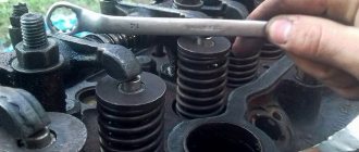
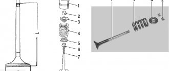
3.4.11.4 To adjust the gap, loosen the lock nut of the screw on the rocker arm of the adjustable valve in accordance with Figure 10 and, turning the screw, set the required gap using the feeler gauge between the rocker arm striker and the end of the valve stem. After setting the gap, tighten the lock nut. After adjusting the valve clearance, replace the cylinder head cover cap.
1 - lock nut; 2 - screw.
Figure 10 — Adjusting the valve clearance.
3.4.12 Replacing the filter element of the diesel fuel fine filter D-245.7, D-245.9, D-245.12S
3.4.12.1 The service life of the filter element depends on the purity of the fuel used.
3.4.12.2 Replace the filter element at 2 TO -2 in accordance with Figure 11, for which:
— drain the fuel from the filter by unscrewing the plug at the bottom of the housing;
— unscrew the nuts securing the cover and remove the cover;
— remove the filter element from the housing;
— wash the internal cavity of the filter housing;
— assemble the filter with a new filter element;
— fill the system with fuel.
1 — filter cover; 2 — filter element; 3 — filter housing; 4 - plug.
Figure 11 — Replacing the filter element of the fine fuel filter.
Unscrew the air bleeder plug on the fuel pump housing and the fitting on the fine fuel filter 1-2 turns. Bleed the system using a booster pump, sequentially closing the plug on the fuel pump body when fuel appears in accordance with Figure 12, and then the fitting on the fine filter.
1- fitting; 2 — booster pump; 3 - plug.
Figure 12 - Removing air from the fuel supply system.
Adjustment on various engine models
The Minsk Plant produces several modifications of diesel engines based on the design of the D-240 engine. The units differ in block configuration, displacement and installation of a turbocharger, which led to an increase in power and a change in the standard distances between moving parts in valve mechanisms.
Engine D-245 of tractor MTZ-82, MTZ-892
After dismantling the top cover and moving the piston in cylinder 1 to TDC (until the valves begin to overlap), it is necessary to adjust the valves located in positions 4, 6, 7 and 8 (counted from the front engine cover). The documentation sets the distance between the rod and the striker to be 0.25 mm for the inlet channel and 0.45 for the outlet. The setting is carried out on a cold diesel engine (warming up to 60° is allowed).
- Loosen the rocker arm nut of the valve being serviced and turn the screw with a screwdriver to achieve the required distance.
- Tighten the locknut of the adjusting screw with a wrench and check the parameters with a feeler gauge. Make sure of the standard value by rotating the rod; if the head of the cylindrical element is worn unevenly, the distance between the striker and the valve stem may change. A damaged or worn rod must be replaced.
- By analogy, adjust the gaps in the remaining valves.
- Rotate the shaft a full turn (until TDC is reached in the last cylinder), and then adjust the distance in the mechanism to the required value for valves 1, 2, 3 and 5.
- Reinstall the removed elements in their original places and check the operation of the power unit.
Engine D-260 of tractor MTZ-1221, MTZ-1523
The manufacturer requires that the valve mechanism be adjusted during maintenance corresponding to 500 hours of operation. Before starting adjustment, it is recommended to check the tightness of the bolts securing the head. It is allowed to tune the motor, warmed up to a temperature of 60°C.
To adjust a 6-cylinder in-line diesel engine, you need to remove the valve cover , and then set the piston of the first cylinder to the uppermost position (by analogy with the D-240 and 245 engines), and then set the clearance in the valves located in positions 3, 5, 7, 10, 11 and 12 (counting is carried out from the radiator of the power plant). The standard distance is 0.25 mm at the inlet and 0.45 mm at the outlet. To determine TDC, it is possible to use the moment of alignment of the pin installed on the timing mechanism drive cover with the mark on the pulley damper.
If the value deviates, adjustments must be made in the following sequence:
- Before starting the adjustment, it is recommended to check the tightness of the fastening of the roller struts with the rocker arms.
- Unscrew the fixing nut on the adjustable valve rocker arm, and then adjust the clearance by turning the screw.
- Tighten the nut and perform an initial check with a feeler gauge.
- Make sure that the distance between the striker and the plane of the valve stem is stable by rotating the drive rod around its axis.
After adjusting the sizes in 6 valves, you need to turn the crankshaft 1 revolution. To check the position, the sixth cylinder is used, in which there must be an overlap of the intake and exhaust valves corresponding to TDC. The sequence of actions when setting up is similar to the algorithm outlined above. It is possible to adjust the parameter in accordance with the order of flashes in the combustion chambers (1-5-3-6-2-4) with the pistons aligned to the top point according to the operating sequence. To transition between cylinders, the shaft is rotated 1/3 of a turn.
Motor characteristics. general information
The use of an internal turbine compressor with adjustable air flow makes it possible to create optimal throttle response when the engine is running. This indicator is ensured by an enhanced torque parameter even at minimum shaft speed. Also, the exhaust gases meet all required standards. —
All motors in the series are designed to work at tempo. conditions up to +40 degrees Celsius. The main area of application of these diesel engines is power plants for construction equipment, road equipment and wheeled tractors.
D-245: general information
The use of a turbine compressor with adjustable air flow makes it possible to create optimal throttle response in the engine. This indicator is ensured by an increased torque parameter with minimal crankshaft speed. At the same time, the exhaust gases meet the required standards.
All motors in this series are designed for normal operation in temperature conditions from -45 to +40 degrees Celsius. The main scope of application of the diesel engines under consideration is power plants for road, construction equipment and wheeled tractors.
Adjusting valves in the D-245 engine
Before you start setting up the D-245 valves, you need to study the features of this unit. The shaft has 5 supports and is driven by the crankshaft and distribution gears. 5 bushings are used as working bearings, which are placed in sections of the block. The front bushing is located in the fan area and is equipped with a collar that secures the camshaft axial shifts; the others are made of cast iron. The steel pushers are overlaid with special cast iron, and the spherical surface has a radius of 750 mm. Angled camshaft cams.
To correctly adjust the D-245 valves, it should be taken into account that the pusher rods are made of steel rod and have a spherical area that fits into the pusher. The valve rocker arms were made of steel, and the axle was fixed using 4 racks. The axis is hollow, equipped with radial holes for oil delivery.
Carry out the adjustment itself in the following sequence
- Remove the cylinder cover cap and look at the fastening of the struts in the rocker axis;
- Turn the crankshaft to overlap in cylinder 1 and adjust the clearance in 4, 6, as well as the seventh and eighth, then turn the shaft 1 turn, setting overlap on the fourth cylinder, adjusting the clearances in the first, as well as the second, third valves.
- To adjust, loosen the lock nut on the valve rocker arm and turn the screw to create the required clearance between the striker and the valve stem. After setting the gap, tighten the locknut properly. After completing the clearance adjustment, replace the cylinder cover cap in the valves.
Check the tightness of the cylinder head bolts after running in in the following order:
- Remove the cap and cover from the cylinder head;
- Remove the rocker arm axle;
- Using a torque wrench, check the tightness of the cylinder head bolts and tighten them if necessary.
Step-by-step instruction
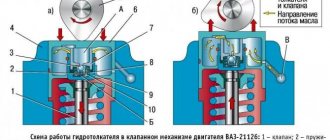
Checking and adjusting the clearances of the D-240 diesel engine: 1
- lock nut,
2
- adjusting screw,
3
- feeler gauge,
4
- rocker arm striker,
5
- valve stem.
1.
Clean the cap and cylinder head cover from dirt and dust so that there are no oily deposits on the outer surface.
2.
Remove the lid cap and wash it in kerosene.
3.
Unscrew the installation bolt and insert its opposite end into the hole in the flywheel housing.
4.
Check the fastenings of the rocker arm shaft supports and, if necessary, tighten them.
5.
Install the KI-9918* device (a device for determining valve clearances) on the intake valve spring plate, releasing the release cam of the movable carriage.
The movable carriage of the device, under the action of a spring, should rest against the striker of the rocker arm. 6.
Press the rocker until the striker stops at the end of the carriage rod and set the indicator arrow to zero.
7.
If the gap does not meet the permissible limits, adjust the valve mechanism according to the readings of the device indicator by screwing in or unscrewing the adjusting screw, having first unscrewed its lock nut.
8.
Rotating the crankshaft 1/2 turn, check and, if necessary, adjust the clearances in the third, fourth and second cylinders, respectively.
9.
Screw the clamp into the hole in the flywheel housing. Install the removed components onto the engine.
* In the absence of the KI-9918 device, perform the following actions after the fourth point:
1.
Set the piston of the first cylinder to the position corresponding to the end of the compression stroke (both valves are closed).
2.
Loosen the locknut of the adjusting screw on the valve rocker arm and, screwing in the screw, use a feeler gauge to set the required gap between the rocker arm striker and the end of the valve.
3.
Tighten the locknut securely and check the gap again with a feeler gauge, turning the pusher rod around its axis.
4.
Upon completion of adjusting the valves of the first cylinder, turn the crankshaft clockwise half a turn (180 degrees) and begin setting the clearance in the valves of the third cylinder. The gaps are adjusted in a sequence corresponding to the operating order of the diesel cylinders (1-3-4-2).
Checking clearances
It is better to check the valves of the D-245 engine in terms of clearances every 15 thousand kilometers. This procedure is also carried out after the cylinder head has been removed, the cylinder head bolts have been tightened, or after a knock appears in the valve compartment. The gap size between the end part of the valve stem and the rocker arm striker on a cold engine is 0.25 mm on the intake valve, and 0.45 mm on the exhaust valve.
To adjust the clearances, it is necessary to loosen the locknut of the rocker arm of the valve being adjusted. Next, by turning the screw, the required value is set (measured using a probe running between the striker of the rod). After the process is completed, the locknuts are tightened and the cap from the cylinder head cover is replaced. The tightening is checked after running in and then every 50 thousand kilometers on a warm unit. After checking, it is necessary to adjust the gap between the rocker arm and the valves, after which you need to tighten the clamps.
Checking and adjusting gaps
It is advisable to check and adjust the valves of the D-245 (Euro-2) engine in terms of clearances every 20 thousand kilometers. This procedure is also carried out after removing the cylinder head, tightening the cylinder head fixing bolts, or when a knock occurs in the valve compartment. The size of the gaps between the rocker arm and the end part of the valve stem on a cold diesel engine should be 0.25 mm on the intake valve and 0.45 mm on the exhaust valve.
To adjust the clearances, it is necessary to loosen the screw lock nut of the rocker arm of the valve being adjusted. Then, by turning the screw, the required value is set, which is measured using a probe between the striker and the end of the rod. At the end of the process, tighten the locknut and replace the cylinder head cover cap. The tightening of the mounting bolts is checked after running-in and every 40 thousand kilometers on a warm power unit. After checking, it is necessary to adjust the gap between the rocker arm and the valve, and then tighten the clamps.
Valve adjustment D-245
D-245 engines are powerful 4-stroke units with 4 cylinders arranged in a row. The unit is equipped with a direct injection system. This ensures an increased level of fuel combustion and, accordingly, increases engine performance.
However, this engine, like any other equipment, is subject to periodic breakdowns. In order for the unit to work correctly, its valves must be adjusted in a timely manner. With some theoretical training, this procedure can be carried out independently.
General information about the D-245 engine
The engine uses an internal turbine compressor with variable air flow. It makes it possible to create optimal throttle response during operation (Figure 1).
Note: This indicator provides an enhanced torque parameter, even if the shaft speed is at a minimum level.
All motors in this group are designed for use in fairly severe temperature conditions (from -40 to +40 degrees).
Figure 1. D-245 - a powerful motor that is installed on large equipment
As a rule, these powerful units are installed on construction and road equipment, as well as large wheeled tractors that are used in agriculture.
Engine D-245
In order to ensure a better level of acceleration, a turbine compressor is used with the ability to adjust the air flow. This ensures an increased level of torque even at a minimum number of crankshaft revolutions. At the same time, such an engine with a turbine exhausts exhaust gases that comply with European standards Euro 3. But the entire series of such engines is intended for use only in ambient temperatures ranging from -45 to +45 degrees. The main place of use of these units is their installation in road, construction, and wheeled equipment.
Adjusting the cylinder head tightening
The order in which the cylinder head bolts are tightened determines the sequence and force with which the flywheel bolts are tightened in the threaded connections. It is important to remember that the cylinder head tightening torque should be in the range of 190-210 Nm. In this case, the stud nuts and bolts must be tightened to capacity.
Adjusting valves in the engine
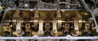
Before you begin to independently adjust the valves of the D-245 engine, you should study the technical structure and features of this part of the engine (Figure 2).
The shaft has 5 supports, and its movement is driven by the crankshaft and timing gears. Instead of working bearings, 5 bushings are used, placed in sections of the block.
Figure 2: Valve adjustment steps
The front bushing is located near the fan. Additionally, it is equipped with a collar that secures the camshaft axial shifts. Other bushings are made of cast iron. The pushers are made of steel, but also reinforced with cast iron. The camshaft cams have a slight slope.
Valve adjustment in D-245 engines is carried out in a clear sequence:
- First, remove the cap from the cylinder cover and determine the fastening of the struts to the rocker axis.
- Next, turn the crankshaft until it overlaps in the first cylinder, and adjust the clearances of valves 4, 6, 7 and 8.
- After this, the shaft is turned one revolution and the overlap is installed near the fourth cylinder and the clearances in the first, second and third valves are adjusted.
To complete the adjustment, the locknut on the valve rocker arm is lowered and the screw is turned so that a gap of the required size is formed between the valve stem and the striker.
Next, tighten the locknut and put the cylinder cover cap in place. After completion of the running-in, additionally check the tightness of the cylinder head bolts.
To do this, remove the cap and cover, remove the rocker arm axis and use a torque wrench to check the tightness of the cylinder head bolts. If they are weakened, additional tightening is performed.
Tips for lapping valves D-245
Experienced mechanics have several secrets that help to carry out technologically correct and high-quality valve grinding (Figure 3).
Firstly, it is customary to grind D-245 valves on special stands and machines. A special paste is applied to the chamfers of the parts, diluted in diesel fuel to the consistency of liquid sour cream. To improve the quality of the paste, oleic or stearic acid is usually added to it.
Secondly, it is necessary to carry out high-quality dismantling of the part. To do this, first unscrew the nuts securing the rocker arm axle struts, and then dismantle it along with the springs.
Figure 3. Lapping is best done on a machine
Unscrew the bolts in the same way and remove the head. Additional parts also need to be removed from the valves: the spring plate, the springs themselves with washers, the sealing collar and guide bushings.
Thirdly, you need to learn how to determine the duration of valve grinding. It is continued until a continuous matte belt with a thickness of at least 1.5 mm appears on the chamfer of the seat and the chamfer of the valve itself. Any breaks or dashes are not allowed; the strip must be continuous and uniform.
After finishing the grinding, the head of the block and the valves themselves are washed. When assembling, the valve stem must be lubricated with machine oil.
In general, grinding can be carried out either manually or using metalworking equipment, but the labor intensity of manual work is much higher.
Recommendations for lapping
Experts recommend grinding in D-245 valves based on the following principles:
- The valves should be ground in on machines or special stands. The chamfers of the parts are lubricated with a special paste, which is diluted in diesel fuel to a consistency reminiscent of liquid sour cream. To improve the quality of the paste, it is advisable to add oleic or stearic acid.
- Dismantling of parts must be done efficiently. This means that first the fastening nuts are unscrewed and only then the springs are dismantled. The bolts are unscrewed in the same way and the head is removed. Next, additional elements are removed from the valves: a spring plate, springs with washers, a sealing collar and bushings.
- The duration of valve grinding during adjustment is also important. This is carried out until a continuous matte belt is formed on the chamfers of the seat and valve, the thickness of which should be about 1.5 mm. Gaps and dashes are unacceptable.
Upon completion of the grinding of the block head and the valves themselves, flushing is done. During assembly, be sure to lubricate the system with machine oil. The grinding process itself can be done manually or using bench-type equipment. The labor intensity in the first case will be many times higher.
[~DETAIL_TEXT] =>
To understand the process of adjusting valves on a ZIL, called “Bychok”, you must first understand what the structure of the D-245 engine itself is. In fact, these are 4-stroke type units, which are equipped with 4 cylinders arranged in one row. This design feature ensures an increased level of fuel fluid combustion, thereby increasing overall performance.
But despite its high performance, the D-245 engine, just like any other devices, is susceptible to various types of breakdowns and malfunctions. Therefore, for the correct operation of the unit, regular adjustment of the equipment valves is required. In most cases, you can perform this procedure yourself.
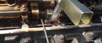
Checking clearances
In order for the D-245 engine to work correctly, the clearance parts are checked after every 15 thousand kilometers. Extraordinary control is required after removing the cylinder head or if an extraneous knock appears in the valve compartment (Figure 4).
Figure 4. Checking gaps schematically
The optimal clearance for a cold engine should be 0.25 mm at the intake valve and 0.45 mm at the exhaust valve.
To adjust the clearances, the locknut of the rocker arm of a particular valve is lowered and the screw begins to turn until the required value is reached. To check, use a special probe between the striker of the rod. At the end of the procedure, the locknuts are tightened and the lid cap is replaced.
The tightening should be checked after the first break-in, and subsequently every 50 thousand kilometers when the engine is warm. After the control run-in, adjust the gap between the valves and the rocker arm, and tighten the clamps.
Detailed step-by-step instructions for adjusting the D-245 valves are given in the video.