Sensor malfunctions
The following symptoms may indicate a malfunction of the crankshaft sensor:
- the engine stops unexpectedly;
- the engine is unstable during idle;
- obvious missing sparks are noticeable;
- Engine power is noticeably reduced, especially on inclines;
- engine speed spontaneously increases or decreases;
- under various dynamic loads, the appearance of detonation is noticeable;
- difficulties starting the engine and much more.
All of the above examples, taken separately or together, indicate that it is time to change the sensor. To fully verify that it is necessary to replace the crankshaft sensor on a VAZ 2110 or other models, you need to conduct testing.
Sensor performance test
There are several ways to check the sensor. Each method requires the presence of certain instruments. Let's look at two main verification methods that give accurate results.
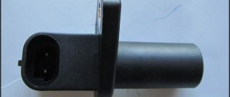
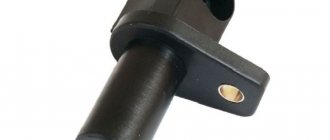
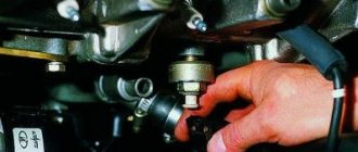
After removing the sensor, and how to do this will be described in detail below, you need to carefully inspect it. A visual inspection will help determine the condition of the core, terminal block and the contacts themselves. If traces of dirt are noticeable on the sensor and prevent a normal inspection, they should be removed using a cloth soaked in alcohol or gasoline. Contacts should also always be clean.
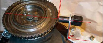
In addition, when dismantling, you need to pay special attention to the distance between the sensor core and the disk. If it is not close to the value of 0.6-1.5 mm, then the sensor most likely has defects. If everything is normal, this does not mean that the sensor is working
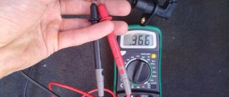
Only an ohmmeter will allow you to determine the presence of obvious malfunctions in the operation of the crankshaft sensor. This device should measure the resistance of the synchronization sensor winding. The normal value output by an ohmmeter should be 550-750 ohms. To be sure, it is recommended to check in advance the exact parameters in the car’s operating instructions, which may vary depending on the manufacturer. If the value given by the ohmmeter measurement differs from those indicated, then there is a problem with the sensor.
If everything is normal, this does not mean that the sensor is working. Only an ohmmeter will allow you to determine the presence of obvious malfunctions in the operation of the crankshaft sensor. This device should measure the resistance of the synchronization sensor winding. The normal value output by an ohmmeter should be 550-750 ohms. To be sure, it is recommended to check in advance the exact parameters in the car’s operating instructions, which may vary depending on the manufacturer. If the value given by the ohmmeter measurement differs from those indicated, then there is a problem with the sensor.
Another verification option involves more extensive testing. To carry it out you will need the following tools:
- voltmeter;
- inductance meter;
- megohmmeter;
- network transformer.
When measurements are carried out using this method, the air temperature should be 20-22 degrees. As for the winding resistance, we measure it using the method described above. So:
- To determine the inductance of the crankshaft speed sensor winding, you will need to use an inductance meter. It will show how an inductive coil, capacitance and resistance work. The normal inductance value should be 200-400 MHz.
- The insulation resistance is checked using a megohmmeter. At a voltage of 500 V, this figure should not exceed 20 MΩ.
Note
If suddenly, during the process of repairing the crankshaft sensor, careless magnetization of the synchronization disk occurs, you will have to use a network transformer for testing. Based on the results that the devices give, you can find out exactly whether the sensor is working or not. Based on the results that the devices give, you can find out exactly whether the sensor is working or not.
Based on the results that the devices give, you can find out exactly whether the sensor is working or not.
Video “An example of replacing DPKV on a VAZ car”
The channel In Sandro's Garage talked about the features of replacing the controller in VAZ cars of the tenth family, as well as Kalina, Grant and Priora.
The crankshaft sensor may become unusable and then it needs to be changed. But first, you should pay close attention to the signs of malfunction to be sure that the sensor really needs to be replaced. These signs are:
- Reduced motor performance of the vehicle.
- Unstable engine idle speed, especially when the car is moving evenly.
- Increased fuel consumption.
- When driving fast, there is a risk of detonation.
- The engine does not start.
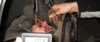
If the crankshaft sensor on a VAZ 2107 fails, then it must be checked for functionality. To do this, you need to prepare a screwdriver and a multimeter.
Set the position on the multimeter, which corresponds to 200 MV. The outputs from the DCPV must be connected to a multimeter. Bring an object, maybe a screwdriver, in close proximity to the core. Voltage surges should appear on the multimeter. If this does not happen, then the sensor is broken and needs to be replaced.
To install a new crankshaft sensor on a VAZ 2107 with your own hands, you will need:
- Tools: 10 mm wrench for hard-to-reach places, several probes of different sizes.
- New crankshaft sensor.
First of all, it is necessary to de-energize the sensor. To do this, you will need to remove the block with wires from it.
Unscrew the mounting screw with a 10 mm socket wrench and remove the DPKV.
Install a new one in place of the broken sensor.
After installing a new DCPV, you should check the distance between the sensor core and the pulley teeth. It should be within the range: 1 mm / - 0.41 mm.
If the numbers are different, this indicates that there is dirt under the device. The sensor may be pushed out or pushed back too far. You cannot reduce the distance, you can only expand it. After installing the sensor, start the engine and check its operation.
Thus, the crankshaft sensor on the VAZ-2107 is a rather important device. If the faults mentioned above occur, first of all you need to check the crankshaft sensor. It does not have a complicated device, and you can check it in the simplest way - measure the resistance of the coil. If there are no diagnostic devices, then you need to contact a professional at a service station.
This is interesting: Hyundai accent brake pads: selection and replacement
How to check DPKV yourself - 3 different ways
Before you start checking the synchronization sensor with instruments, you must mark its initial position on the engine. After removing the electronic device, inspect it for external damage. If the sensor is dirty, it is necessary to clean it, including removing corrosion from the contacts, if any, using gasoline or alcohol. If there is no external damage to the sensor, you can begin to diagnose it using instruments.
How to check the crankshaft position sensor with an ohmmeter
In order to check the crankshaft sensor with an Ohmmeter, you must perform the following procedure:
- The first thing to do is to inspect the device while it is installed on the car, or rather, check for a gap between it and the synchronization disk. It is quite possible that there is no gap there due to the fact that dirt has adhered to the sensor or disk, which led to the violation.
- If everything is in order with the gap, we will remove the device from the car.
- The next stage is assessing the external state. The sensor body must be intact, without signs of damage, the core must be clean, the contact terminals must be free of traces of oxidation, and the wires must not be damaged.
- If external contamination is visible on the DPKV, you can wash it before checking (to do this, use only pure gasoline or alcohol), and also clean the contacts with a file.
- After cleaning, rinsing and drying, you can start taking measurements. To do this, switch the multimeter to ohmmeter mode and connect the probes to the sensor contacts.
- When measuring, a working DPKV should show a resistance in the range of 550-570 Ohms.
Checking the inductance of the crankshaft sensor
Checking the inductance of the crankshaft position sensor is a more complex method. To do this you will need:
- voltmeter, preferably digital;
- megohmmeter;
- inductance meter;
- network transformer.
For correct indicators when measuring the sensor, the recommended air temperature is 20-22 0 C. We measure the winding resistance with an ohmmeter and the method indicated above.
To measure the inductance of the crankshaft speed sensor winding, an inductance meter (inductive coil, capacitance and resistance) is used. The inductance should be in the range of 200-400 MHz.
Using a megohmmeter, the insulation resistance is checked. This parameter at a voltage of 500V should not be higher than 20 MOhm.
If during the repair of the sensor the synchronization disk is inadvertently magnetized, then demagnetization is carried out using a network transformer. Based on the results obtained during test measurements, you receive data about the sensor’s malfunction, or, conversely, its serviceability
When installing an old or new sensor, carefully install it in the seat according to the marks. Do not forget about the distance that should be between the synchronization disk and the core (0.5-1.5 mm)
Based on the results obtained during test measurements, you receive data about the malfunction of the sensor, or, conversely, its serviceability. When installing an old or new sensor, carefully install it in the seat according to the marks. Do not forget about the distance that should be between the synchronization disk and the core (0.5-1.5 mm).
How to Test a Crankshaft Position Sensor Using an Oscilloscope
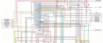
A digital oscilloscope allows you to effectively monitor and find faults in injection system sensors. Now we will talk in detail about checking the crankshaft sensor using an oscillogram:
The crankshaft position sensor (CPS) is the most important in the injection system; it synchronizes the operation of the electronic engine control unit. The VAZ DPKV signal is a series of repeating electrical voltage pulses generated by the sensor when the crankshaft rotates.
The drive disk is a 60-2 gear, i.e. 58 equidistant teeth and two missing teeth for synchronization. When the drive disk rotates together with the crankshaft, the depressions change the magnetic flux in the sensor's magnetic circuit, inducing alternating current voltage pulses in its winding. The oscillogram of the inductive DPKV has the following form:
Here it is worth paying attention to the signal amplitude and pulse shape. If the turns in the sensor winding are short-circuited, the signal amplitude will be reduced
Also, from the oscillogram it is easy to calculate the runout of the drive disk and damage to the teeth. On some foreign cars, a Hall sensor is used as a DPKV, producing rectangular pulses.
And this is how the crankshaft and camshaft position sensors of Nissan engines work synchronously. Based on the rising edges of the signals, the displacement of the shafts relative to each other can be determined.
Crankshaft sensor "VAZ-2110": malfunctions and signs of breakdowns
Can this part break? Typically, on a VAZ-2110, the crankshaft sensor rarely fails. However, if it malfunctions (or the generator pulley does not work correctly), the red “CHECK ENGINE” lamp lights up on the instrument panel, which literally translates as “check engine.” In this case, code 19 or 35 appears in the controller error memory.
Of course, the most severe case when the crankshaft sensor fails is the inability to start the engine normally. In this case, we can say that DPKV does not work at all. The solution to this problem can only be its complete replacement.
Very often the crankshaft position sensor fails gradually. At the same time, the driver feels a significant drop in engine power, “dips” and even detonation begin at high speeds. Also, a symptom of malfunctions of such a device can be floating (unstable) engine speed at idle. On the VAZ-2110, the crankshaft injector sensor sometimes causes increased fuel consumption. Although it is possible that the problem is hidden in a weak connection or broken wires, in any case this part must be checked.
Replacing the crankshaft sensor on a VAZ 2114 with your own hands
The shaft position sensors on the VAZ 2114 differ not only in their design, but also in their operating principle.
Inductive-type DPKVs have a metal rod with a magnet, which is needed to magnetize it. A copper winding is wound over the rod. The principle of its operation is to give a signal when a steel object is nearby.
DPKV of the second type works according to a different scheme. Inside such a device there is a hall sensor. If you bring a metal object to it, its state will change.
Pulse-type devices are also often used. They generate pulses of a specific frequency. If there is a metal object nearby, the generation frequency will also change.
Where is?
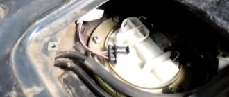
It is not difficult to detect the shaft position sensor on a VAZ 2114. It is located under the hood near the crankshaft pulley and is attached to the oil pump with a bolt.
Causes and symptoms of malfunction
A sensor can malfunction or even fail for a variety of reasons. Often, the most common dirt adhering to the DPKV can cause data reading errors.
- Unstable operation at idle.
- Spontaneous increase and decrease in power unit speed.
- Reduced engine power.
- During acceleration, “dips” appear.
- The car is difficult to start.
- As a rule, in such cases, the only way out is to replace the DPKV.
- If error 0335 or 0336 appears, then in this case with a high degree of probability it can be stated that the wire near the connector is broken. In this case, you just need to replace the connector.
Oscilloscope reading of the crankshaft sensor
- Physical damage to the case.
- Short circuit of the winding turns as a result of which incorrect data is transmitted to the control unit.
- Wear.
- Damage to pulley teeth.
Step-by-step replacement instructions
You can check the condition of the sensor in different ways, but specialists at a service station can do this better and more accurately. Before checking, of course, it needs to be removed and this is done very simply and even a novice car enthusiast can do it. If you are sure that the sensor is not working correctly, you can also replace it yourself.
- Turn off the ignition.
- Raise the hood cover.
- Find where the sensor is installed.
- If it and the place where it is installed are very dirty, then you must clean it with a rag or brush.
- We remove the block.
Removing the block from the connector Unscrew the bolt.
Unscrew the fastening bolt. Remove the shaft position sensor.
We take out the required part
We check the generator drive toothed pulley for damage and other malfunctions. This is very important because if it becomes damaged, data will not be transferred correctly. Before installing a new sensor, clean the installation site. We install a new one or an old one, if you determine that it is working. Tighten the bolt. In this case, it is necessary to strictly control that the moment is not higher than 8-12 Newton meters. Using a feeler gauge, we control the gap between the pulley and the DPKV core. It should not exceed one millimeter. The maximum deviation is 0.4 mm in the direction of increase.
Required clearance
Let's start the engine. If it starts confidently, and the operation of the VAZ 2114 power unit is stable, then we can state that the work was done correctly.
As you can see, there is nothing complicated and you shouldn’t go to a service station unless absolutely necessary, spending extra money.
Video “Replacing DPKV on VAZ 2110-2114”
This video shows how to correctly replace the crankshaft position sensor on VAZ 2110-2114 cars. Recommendations are also given on how to avoid this malfunction.
Self-replacement of the sensor
If after checking we are convinced that the sensor is faulty, it should be replaced. To do this, you need to contact either a car service center or do it yourself.
To replace the sensor we only need a 22mm wrench.
- Disconnect the negative terminal of the battery
- Carefully pull out the wire block from the sensor
- Using a 22mm wrench, carefully unscrew the old sensor and install the new one.
As you can see, everything is simple and easy. The main problem at the initial stage is determining whether the sensor is faulty. Is this really the reason, after we are convinced of its malfunction, we can safely replace it with a new one.
Within 52-53 Ohms. The resistance between terminals A-C and B-D should be high (tend to infinity). The faulty idle air regulator on the VAZ 2107 needs to be replaced.
To do this, we apply 12 V voltage from the battery to terminal D of the idle air control regulator (the connection of the wire to the terminal must be insulated). With the bare end of the wire connected to the negative terminal of the battery, briefly touch terminal C of the idle speed control. Since the valve moves slowly, we touch it repeatedly, simulating the operation of a switching power supply. After installing the needle in its extreme position, check the protrusion of the needle, which should be 23 mm.
Installing the idle air control valve is performed in reverse order. Taken from: https://car-exotic.com.
Sources
- https://remontautomobilya.ru/zamena-datchika-kisloroda-lada-granta-podrobnaya-instrukciya-s-foto-i-video.html
- https://mir-autoproma.ru/luchshie-otvety/3020-gde-na-vaz-21074-datchik-holostogo-hoda.html
What is DPKV?
DPKV is an electromagnetic device that determines the synchronization of the functioning of fuel injectors and the injection system. In a fuel injection system, this device is one of the most basic, since without it the system would be impossible to operate.
Failed DPKV
Failure of this sensor will eventually cause engine malfunctions. And although such breakdowns are not very common in practice, if you decide to go on a long journey, it is better to have a working device in stock. After all, if it breaks down, driving the car will be impossible.
The DPKV is located near the generator drive shaft using special fasteners. It should be installed with a small gap between the device itself and the gear shaft. Ideally, this gap should not exceed 1 mm, and it is set by selecting certain washers. The principle of operation of the regulator is to transmit certain readings, by which the controller will determine which specific cylinder the combustible mixture should be supplied to and at what interval.
What is a crankshaft position sensor on a vase
The induction type crankshaft position sensor is installed next to a special disk located in conjunction with the crankshaft drive pulley. The special disk is called a reference or master disk. Together with it, it ensures angular synchronization of the operation of the control unit. Skipping two teeth out of 60 on the disk allows the system to determine the TDC of the 1st or 4th cylinder. The 19th tooth after skipping should face the DPKV rod, and the mark on the camshaft should be against the bent reflector bracket. The gap between the sensor and the top of the disc tooth is in the range of 0.8-1.0 mm. The sensor winding resistance is 880-900 Ohms. To reduce noise levels, the crankshaft sensor conductor is shielded.
After turning on the ignition, the control program of the unit is in the waiting mode for the synchronization pulse signal from the crankshaft position sensor. When the crankshaft rotates, the sync pulse signal arrives instantly to the control unit, which, in accordance with their frequency, switches the electrical circuit of the injectors and the ignition coil channels to ground.
The control unit program algorithm works on the principle of reading 58 teeth passing by the magnetic core of the DPKV, skipping two. The skipping of two teeth is a reference mark for determining the piston of the first (fourth) cylinder in the top dead center position, from which the unit analyzes and distributes the switching signals that control the opening of the injectors and the spark on the spark plugs over the engine operating strokes.
The control unit detects a short-term failure in the synchronization system and tries to resynchronize the control process. If it is impossible to restore the synchronization mode (lack of contact on the DPKV connector, cable break, mechanical damage or broken master disk), the system issues an error signal to the instrument panel, lighting the Check Engine warning lamp. The engine will stall and it will be impossible to start it.
The crankshaft position sensor is a reliable device and rarely fails, but sometimes malfunctions occur due to the inattentive or negligent attitude of specialists servicing the engine.
For example, a VAZ-2112 has a 21124 engine (16 valves where the DPKV cable is located very close to the exhaust manifold) and the problem usually arises after a repair, when the chip on the cable is not secured to the bracket. When the cable comes into contact with a hot pipe, it melts, destroying the connection circuit and the car stalls.
Another example would be a poorly manufactured drive disc, the rubber coupling of which may rotate along the internal connection.
The electronic control unit, receiving a single signal from the DPKV, determines the position relative to the crankshaft at each moment of time, calculating its rotation frequency and angular velocity.
Based on sinusoidal signals issued by the crankshaft position sensor, a wide range of problems are solved:
- Determination at a given time of the position of the piston of the first (or fourth) cylinder.
- Control of fuel injection timing and injector open duration.
- Ignition system control.
- Control of variable valve timing system;
- Control of the fuel vapor absorption system;
- Ensuring the operation of other additional systems related to engine speed (for example, electric power steering).
Thus, the DPKV ensures the functioning of the power unit, determining with high accuracy the operation of its two main systems - ignition and fuel injection.
Before purchasing a DPKV to replace it, you need to clarify the type of device installed on the engine.
Purpose, device and principle of operation
The engine crankshaft position sensor in a car performs the main adjustment of the fuel injection system. Its presence ensures synchronous operation of each engine injector and the ignition system as a whole.
The controller consists of the following components:
- 1 — nylon frame of the device;
- 2 - magnetic cores, these elements are made of steel;
- 3 - winding set, for which thinned copper cable is used;
- 4 - insulating layer of the electrical circuit, usually made in the form of enamel or resin.
Schematic design of the DPKV.
Unstable operation of the controller will lead to interruptions in timing when supplying fuel. When the device operates, the vehicle's control module, which is a microcontroller, ensures the correct position of the piston at a specific period of time for each cylinder of the internal combustion engine.
To ensure adjustment through the device, the process is built according to the following algorithm:
- The crankshaft of the power unit is equipped with a special gear shaft. There are two missing teeth on it, this was done on purpose.
- When the car's engine crankshaft begins to move, all the teeth pass in close proximity to the controller. This contributes to serious distortion of its magnetic field.
- As the shaft passes, signals are generated in the controller's induction coil. Packet pulses are transmitted to the information base, which is contained in the memory of the microcontroller. The two teeth that are missing on the shaft are considered the starting point and also the zero point. Due to the absence of these teeth, the microprocessor device diagnoses the original location of the crankshaft.
- The microprocessor inside the car then counts the number of signals that were sent by the device. A procedure is carried out to determine the position of the crankshaft at a certain period of time.
- The processed pulse data is then transmitted by the control unit to the controller, which is used to activate the fuel injector. The latter supplies fuel to the ignition system.
If the crankshaft position sensor is working correctly, the car's engine will operate at maximum performance. To produce maximum power, the power unit will require a minimum of fuel.
Separately, we should talk about the different types of devices:
- Magnetic induction DPKV. This type of device does not require a separate battery for power. For a control module pulse, a voltage value is initiated at a specific time. This occurs when a synchronization tooth passes through a magnetic field. A magnetic field appears around the controller, and the device itself controls the shaft speed and can be used as a speed controller.
- Hall controller, its operation is based on the Hall effect. This indicates that current transmission begins the moment a changing field is applied to the device. The synchronization shaft overlaps the field itself, interacting through teeth with the field that appears around the controller. The controller, whose operation is based on the Hall effect, is used as an ignition distribution device.
- Optical type device. This type of controller includes a shaft that performs synchronization through holes or teeth. The disk blocks the light flux passing between the diode element and the receiver. The latter processes the incoming light flux into a signal. As a result, voltage is supplied to the microprocessor module.
Inductive crankshaft position controller
DPKV Hall
Optical crankshaft position controller
How DPKV works and how it works
Before we talk about repair and diagnostics of the crankshaft position sensor, we should talk about what these sensors generally are and what the operating principle of such devices is. So, there are three main types of crankshaft position sensors:
- magnetic induction;
- optical;
- Hall sensors;
An electrical voltage is induced in a magnetic sensor when the teeth of the timing disk pass through the magnetic field that surrounds the sensor. Such a sensor is quite simple, and most importantly, it does not require additional electricity to operate.
In an optical sensor, the teeth of the timing disk interrupt the light beam as they pass between the LED and the light-sensing element. And here, for the sensor to work, a certain minimum of electricity is needed, otherwise the diode simply will not light.
Hall sensors are based on the effect of the same name and operate on the principle that an alternating magnetic field intersects the synchronization disk with the constant field of the sensor.
Based on the DPKV readings, the position of the crankshaft is determined, as well as its rotation speed. Thanks to this, it is possible to synchronize the operation of the engine in general and the fuel supply with the ignition system in particular.
Types of sensors
After it has become clear what the crankshaft sensor on the VAZ-2107 and other cars is responsible for, it is worth highlighting the main types of DCPV. At the moment there are several varieties. The table shows modern types of crankshaft position sensors with a description of their operating principle.
| Sensor type | Principle of operation |
| Induction | Its action is based on the use of a magnetized core wrapped in copper wire. The ends of the wire are brought out in order to measure voltage changes. The sensor is mainly used in modern cars. |
| Optic | It works using an LED that emits a beam of light and a receiving device. When a control tooth passes, the beam of light is interrupted, which is recorded by the monitoring device. The collected information is sent to the ECU. |
| Hall Sensor | It works due to a magnet that is installed on the crankshaft and which is fixed. When DC movement begins in the sensor, it is immediately recorded on the synchronizing disk. |