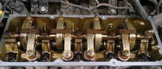
Features of adjusting the valves of the MTZ-80 tractor
It is recommended to tighten the cylinder heads at the very beginning. This will help protect the studs and threads from deformation and damage.
In order to adjust the MTZ valves, you must:
- Loosen the head nuts to gain access to the valve cover.
- Remove the cap located on the lid.
- Check the strength of the roller mounting screws.
- Place the piston part from the first cylinder at the dead center, which is located at the top of the mechanism.
- Loosen the tension on the lock nut from the adjusting screw located on the rocker arm.
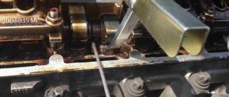
- Using feeler gauges, set the required gap between the striker and the end of the valve. To do this, you need to screw in or unscrew the bolts. The probes should enter the gap with a little force, but they should not be allowed to be pinched. In the service, adjustment of MTZ-80 valves is carried out using 0.35 mm probes.
- After setting the required gap, return the lock nut to its place.
- Using feeler gauges, check the set distance between the valves by turning the push rod of the retarding mechanism around its axis.
The entire procedure must be carried out in the order of operation of the cylindrical elements of the tractor: 3, 4, 1, 2. Before adjusting each element, you need to rotate the crankshaft of the power unit 180° clockwise.
Adjustment on a cold engine
In order for a beginner to easily set the valve clearances on a cold D-240 engine, which the manufacturer equips with the Belarus MTR-80 tractor model, it is better to use a special device KI-9918.
- Using a rag soaked in kerosene, it is necessary to clean the cylinder head cover from oil deposits and dirt particles.
- Disconnect the lid cap and wash it in a kerosene “bath”.
- Unscrew the installation bolt and place the other end into the hole located in the engine flywheel housing.
- Check the rocker arm shafts for secure fastening and, if necessary, tighten them.
- Next, the movable carriage KI-9918 must be lowered using the release cam mechanism and the device must be installed on the intake valve spring plate; the carriage must rest against the rocker arm striker.
- Then you need to press the rocker arm so that the striker rests close to the carriage rod, and set “zero” on the KI-9918.
- Set the required gap, which for cold D-240 should be no more than 0.25 millimeters. It is installed using an adjusting screw, which is tightened as necessary.
- Repeat the procedure for cylinders 3, 4 and 2, sequentially turning the crankshaft half a turn.
- Assemble the mechanisms.
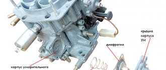
Fuel injection adjustment
To adjust the fuel injection valves, you don’t need any special tools or equipment; just a wrench, a 0.3 mm feeler gauge and a screwdriver are enough. First, you must carefully remove the high pressure fuel pump (HPFP) pipes. Then, using a wrench, you need to slowly crank the engine crankshaft using the ratchet until diesel fuel appears in the fitting. In the cylinder where fuel appears earlier, the valve needs to be adjusted. The cylinder valve clearances are adjusted according to the pressure gauge.
Checking and adjusting the setting angle of fuel injection advance on a diesel engine
Do-it-yourself valve adjustment for VAZ 2106
Maintenance » Checking and adjusting the setting angle of fuel injection advance on a diesel engine In case of difficulty starting a diesel engine, smoky exhaust, as well as when replacing or installing a fuel pump after checking at the stand every 120 thousand km or repairing a diesel engine, be sure to check the setting angle of fuel injection advance to diesel.
The values for the setting angle of fuel injection advance are given in Table 13. Table 13
| High pressure fuel pump | Diesel | |
| D-245.7E2 | D-245.9E2 | D-245.30E2 |
| Installation fuel injection advance angle, degrees of crankshaft rotation | ||
| 773.1111005-20.05 | 2,5±0,5 | |
| 773.1111005-20.06 | 3,0±0,5 | |
| 773.1111005-20.07 | 4,0±0,5 |
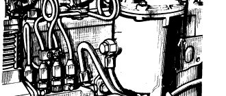
Figure 24. Sketch of the control device
- compression nut
- high pressure tube
Check the setting angle of fuel injection advance with fuel pumps, 773 (JSC YaZDA) in the following sequence:
- set the piston of the first cylinder on the compression stroke 40–50° before TDC;
- set the regulator control lever to the position corresponding to the maximum fuel supply;
- disconnect the high-pressure pipe from the fitting of the first section of the pump and instead connect a control device, which is a piece of high-pressure pipe 100...120 mm long with a pressure nut at one end and the other end bent to the side by 150...170° in accordance with Figure 24 ;
- fill the fuel pump with fuel, remove air from the low-pressure system and create excess pressure with a manual priming pump until a continuous stream of fuel appears from the control device tube;
- Slowly rotating the diesel crankshaft clockwise and maintaining excess pressure in the pump head (with a bleeder pump), monitor the flow of fuel from the control device. At the moment the fuel flow stops (up to 1 drop per 10 seconds is allowed), stop rotating the crankshaft;
- Unscrew the retainer from the threaded hole in the rear sheet in accordance with Figure 25 and insert it with the reverse side into the same hole until it stops in the flywheel, while the retainer must coincide with the hole in the flywheel (this means that the piston of the first cylinder is installed in a position corresponding to the installation angle fuel injection timing indicated in table 13).
Figure 25. Installing the retainer into the hole in the backsheet and flywheel
If the latch does not match the hole in the flywheel, make an adjustment by doing the following:
- remove the hatch cover in accordance with Figure 26;
- align the lock with the hole in the flywheel by turning the crankshaft in one direction or the other;
- loosen the nuts securing the fuel pump drive gear by 1...1.5 turns;
- Using a wrench, turn the fuel pump shaft counterclockwise by the nut until the pins stop against the edge of the groove of the fuel pump drive gear;
- create excess pressure in the fuel pump head until a continuous stream of fuel appears from the control device tube;
- by turning the pump shaft clockwise and maintaining excess pressure, monitor the flow of fuel from the control device;
- when the fuel flow stops, stop rotating the shaft and fix it by tightening the nuts securing the drive coupling half to the drive gear.
Recheck the timing of the start of fuel supply.
Disconnect the control device and reinstall the high pressure pipe and manhole cover. Screw the fastener into the hole in the back sheet.
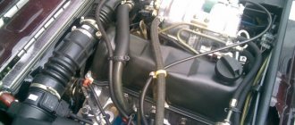
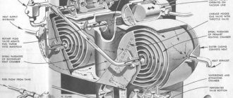
Fuel pump drive
Figure 26. Fuel pump drive
Adjusting valves MTZ-82
This procedure is necessary in cases where a failure occurs in the tractor system: when there is a knock in the engine, a violation of the thermal regime in the engine, after major repairs of the vehicle, etc.
Many users are interested in the question of how the valve elements are adjusted: the sequence (order) on the valve adjustment machine is carried out in the order of operation of the cylindrical elements.
The procedure is carried out as follows:
- Before setting the required gaps between the valve parts, it is necessary to warm up the tractor power unit. The temperature of the working fluid in the engine should not be lower than +75°C.
- After the engine has warmed up, unscrew the top cap from the valve.
- Then you need to unscrew the axis of the rocker arms and oil supply.
- When all the caps are unscrewed, you need to check the tightness of the block struts using a torque wrench. First, check the piston of the first cylindrical element, then the second, etc.
- After this, you should return the axial element to its place and stretch the struts, and then adjust the gaps between the valves.
- After setting the gap, you need to securely fix all the fastening nuts of the power mechanism.
This procedure can be carried out independently only if all spare parts are factory-made, i.e. our own from MTZ-82.
The algorithm of actions is similar for the following tractor models: MTZ-80.1, MTZ-82.1 and MTZ-82.2.
Adjusting valves with cylinder head broaching
In order to make the adjustment, you must:
- Place the vehicle on a special platform.
- Warm up the engine to a temperature of +60…+70°C.
- Remove the power unit.
- Disassemble the engine according to the owner's manual.
- Remove the cover from the valve box.
- Inspect the rocker shaft mounting bolts and nuts.
- The piston mechanism must be rotated to the highest dead center position.
- Inspect the cylinders; 2 valve elements must be closed.
- The gap that has formed between the rocker arm and the valves should be checked using feeler gauges. If a probe with a diameter of 0.35 mm passes into this gap freely, but a probe with a diameter of 0.4 mm does not pass, then the gap is normal. Otherwise, adjustments must be made.
- Unscrew the locknut and fastening nuts.
- Clamp a probe with a diameter of 0.25 using an adjusting screw between the working area of the rocker arms and the ends.
- Tighten all mounting bolts.
- Using the flywheel, turn the crankshaft mechanism half a turn and adjust cylindrical element No. 3.
- After this, adjust the valves of the cylindrical parts numbered 4 and 2.
- Reassemble the engine and install it back on the tractor.
- Bring in the vehicle for inspection.
Adjustment procedure
The need to install injection arises when replacing a high-pressure fuel pump (HPF) or installing it after repair, as well as after repairing the piston group of a diesel engine. The adjustment is carried out provided that the fuel equipment, injection pump and the adjusted gas distribution mechanism of the diesel engine are in good working order. The installation process consists of the sequential operations described below.
Installing the first cylinder on the compression stroke
On the right side, in the direction of travel of the machine, in the wall of the engine mounting to the clutch housing, above the longitudinal beam of the tractor frame near the oil filler neck, there is an installation dipstick. With its short threaded part it is screwed into the mounting wall and with its long threadless part it is installed outside. If it is necessary to install the first cylinder in the “compression” stroke position, the dipstick is installed in the hole, resting its long part against the engine flywheel. Slowly turning the diesel crankshaft, find the position at which the probe will fall into the hole on the flywheel and enter the body of the part completely by 4-5 cm
It is important not to confuse the installation hole with the technological, balancing drillings of the flywheel, which are much shallower in depth. The found position corresponds to an advance of 26 ̊ before the piston of the first or fourth cylinder approaches TDC
This position corresponds to the technical requirements of D 240 for setting the start of fuel injection into the cylinder during the “compression” stroke. To determine which of the cylinders in the first or fourth the “compression” stroke has begun, you need to remove the valve cover. A pair of closed valves will indicate in which of the two cylinders (first or fourth) the “compression” stroke has begun.
Disconnecting the pump drive
To establish synchronization of the engine and fuel injection pump operating cycles, you need to understand that the pump drive connecting through the engine timing gears must be disconnected. The drive is connected by connecting the holes of the pump drive gear 4 with the adjusting holes of a special washer 5 along the perimeter through a splined bushing fixed to the pump shaft. Access to the drive is achieved by opening the front cover 8 of the pump. To disconnect, unscrew two fastening bolts 3 with strip 7 and remove the adjusting washer from the splined sleeve. In this position, the rotation of the shaft cranks will not be transmitted through the camshaft gear drive to the pump shaft 6.
Adjusting valves on MTZ-245
In order to adjust the valve mechanisms on the D-245 power unit, it is recommended to contact a service center; adjustment costs an average of 5,000 rubles.
Having the necessary skills, you can make the adjustment yourself.
To do this you need:
- Unscrew the nuts that secure the struts of the axial part of the rocker arms.
- Completely dismantle the axial part together with the spring.
- Unscrew the cylinder head cover and remove it from the power unit.
- Inspect the valve (adjustable) for damage; adjustment should be carried out on specially equipped platforms or machines.
- Apply a paste-like lapping agent to the injectors. It is recommended to add stearic fatty acid to the paste.
- Continue adjustment until a wide matte edge appears on the injectors and seats. There should be no rupture of the belts.
- Wash the cylinder head and valve parts.
- Lubricate the rod part with oil liquid.
- The gap between the rocker arm striker and the end of the rod should not be more than 0.35 mm on an intake-type mechanism and no more than 0.45 mm on an exhaust-type mechanism.
- Tighten the cylinder block head fixing bolts. This will help eliminate extraneous knocking in the valve section of the power unit.
Repair manual. Service
All drivers sooner or later encounter equipment malfunctions. Here are some typical problems and methods for eliminating them.
| Malfunction | Solution |
| Presence of air in the fuel system | Blowing the system with a manual pump |
| Injector needle stuck | Identifying a faulty nozzle, washing/replacing the nozzle, adjusting the nozzle |
| Oil entering the combustion chamber | Replacement of parts of the sleeve-piston group |
| Coolant boiling | Eliminating coolant leaks from the system, cleaning the radiator |
Adjusting valves on MTZ-1221
The procedure for adjusting valve parts on the T-1221 Belarus tractor:
- Place the vehicle on a special platform.
- Remove and warm up the engine of the unit to +60°C.
- Disassemble the motor.
- Remove the power unit cylinder head cover cap.
- Check the tightness of the fasteners of all struts of the axial part of the mechanism.
- Rotate the crankshaft until it closes the valves on cylinder number 1.
- Carry out the procedure for adjusting the intervals in the order of operation of the cylinders: 3, 5, 7, 10, 11, 12.
- The gap between the end-type rod and the rocker arms should not exceed 0.4 mm (intake mechanism) and 0.45 (exhaust mechanism).
- Rotate the crankshaft 360°.
- Install the overlap on cylinder No. 6.
- Perform adjustments in cylinders No. 1, 2, 4, 6, 8, 9.
- Unscrew the adjusting mechanism locknut using a special wrench and screwdriver.
- Using a feeler gauge, set the required gap.
- Tighten the lock nut.
- Check the gap adjusted with the feeler gauge.
- Reinstall all parts.
- Start the tractor to check the operation of all adjusted mechanisms.
Adjusting the thermal clearance in the valves of the D-240 engine
The valve clearance must be adjusted when the engine is cold. For the D-240 engine, the gap in the intake valves is 0.25 mm, for the exhaust valves - 0.30 mm.
- Clean the cap and cylinder head cover from dirt and dust so that there are no oily deposits on the outer surface.
- Remove the lid cap and wash it in kerosene.
- Unscrew the installation bolt and insert its opposite end into the hole in the flywheel housing.
- Check the fastenings of the rocker arm shafts and, if necessary, tighten them.
- Install the KI-9918 device on the intake valve spring plate, releasing the release cam of the movable carriage. The movable carriage of the device, under the action of a spring, should rest against the striker of the rocker arm.
- Press the rocker until the striker touches the end of the carriage rod and set the indicator needle to zero.
- If the gap does not correspond to the permissible limits, adjust the valve mechanism according to the readings of the device indicator by screwing in or unscrewing the adjusting screw, having first unscrewed its lock nut.
- Rotating the crankshaft 1/2 turn, check and, if necessary, adjust the clearances in the third, fourth and second cylinders, respectively.
- Screw the retainer into the hole in the flywheel housing. Install the removed components onto the engine.
Rice. Checking and adjusting diesel clearances: 1 - lock nut, 2 - adjusting screw, 3 - feeler gauge, 4 - rocker arm striker, 5 - valve stem.
If the KI-9918 device is not available, perform the following steps after the fourth point:
- Set the piston of the first cylinder to the position corresponding to the end of the compression stroke (both valves are closed).
- Loosen the locknut of the adjusting screw on the valve rocker arm and, screwing in the screw, use a feeler gauge to set the required gap between the rocker arm striker and the end of the valve.
- Tighten the locknut securely and check the gap again with a feeler gauge, turning the pusher rod around its axis.
- After adjusting the valves ⭐ of the first cylinder, turn the crankshaft clockwise half a turn (180 degrees) and begin setting the valve clearance of the third cylinder. The gaps are adjusted in a sequence corresponding to the operating order of the diesel cylinders (1-3-4-2).
- Screw the retainer into the hole in the flywheel housing. Install the removed components onto the engine.
How to adjust valves MTZ-1523 and 892
Adjustment must be carried out every 20,000 km of the vehicle, after removing the cylinder head, tightening the mounting bolts and when noise appears in the valve area.
To carry out this procedure you will need the following tools:
- wrench;
- measuring probes;
- screwdriver;
- micrometer.
Procedure during adjustment:
- Warm up the engine to a temperature of +60°C.
- Place the tractor on a special platform or stand.
- Remove the vehicle engine.
- Remove the mounting of the roller stands.
- Unscrew the cap from the cylindrical block.
- Inspect the axle mounting system.
- Rotate the crankshaft mechanism.
- Adjust the gaps in the cylindrical compartments numbered 4, 6, 7 and 8.
- Turn the crankshaft 1 revolution, blocking cylindrical element No. 4.
- Adjust the gaps in cylinders numbered 1, 2, 3 and 5.
- Loosen the lock nut between the end of the valve stem.
- Set the required gap using a feeler gauge with a diameter of 0.3 mm.
- Tighten the lock nut until it stops.
- Replace the cylindrical block cap.
- Install the motor.
After adjustment, it is recommended to start the tractor for a control check.