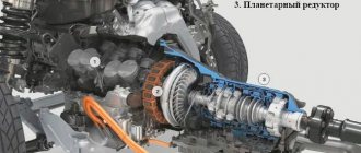
Five-speed gearboxes
Three-shaft gearboxes.
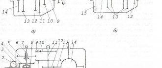
The gearbox of the ZIL-433360 car is a three-shaft, three-way, five-speed with two synchronizers for engaging second and third, fourth and fifth gears (Fig. 12.7). The gearbox parts are mounted in a cast iron crankcase closed with a lid. The winch drive power take-off box is installed on the right hatch; the left hatch is closed with a lid.
In the right wall of the crankcase there is a threaded filler plug through which the gearbox is filled with oil. In the left wall of the crankcase at the bottom there is a drain hole, closed
Rice. 12.7. Five-speed gearbox of the ZIL-433360 car: 1
- input shaft;
2, 10, 12, 21, 22, 24, 27 —
bearings;
3, 20 —
constant mesh gears;
4 —
synchronizer for fourth and fifth gears;
5, 18
— fourth gear gears;
6, 17 —
third gear gears;
7 — synchronizer for second and third gears; 8, /5
- second gear gears;
9
— movable gear wheel of first gear and reverse gear;
11, 23 —
sealing cuffs;
13
- secondary shaft;
14
— first gear gear;
16
— reverse gear of the intermediate shaft;
19
— intermediate shaft;
25
- block of reverse gears;
26 —
spacer sleeve
created by a screw plug, which is equipped with a magnet that attracts wear debris from the oil.
Primary shaft 1
is the drive shaft of the gearbox.
It is manufactured integrally with the constant mesh gear 3
and is mounted on two bearings.
The front bearing 24
is installed in the bore of the crankshaft flange.
Rear bearing 2 -
in the front wall of the gearbox housing.
To eliminate oil leakage from the crankcase, a rubber self-tightening sealing coupling 23
. Intermediate shaft 19
made of steel 25ХГМ together with gear wheel
14
of the first gear.
It is installed in the crankcase with the front end on a cylindrical roller bearing 21,
and the rear end on bearing
12.
Gears
20, 18, 17, 15
and
16
of constant engagement of the fourth, third, second and reverse gears are secured to the shaft with keys, respectively.
Secondary shaft 13
is the driven shaft of the gearbox.
It is made of steel 25ХГМ and is installed with the front end in the bore of the input shaft on bearing 22,
and the rear end in the crankcase wall on bearing
10.
The bearing cover has a self-clamping rubber sealing collar
11,
which prevents oil leakage from the gearbox.
A gear can move along the shaft splines 9
engaging first gear and reverse gear; in addition, gear wheels
8, 6
, 5 of second, third and fourth gears, respectively, are freely mounted on the shaft, and are constantly engaged with the corresponding gear wheels of the intermediate shaft. All constant mesh gears are helical. The gear wheels of the second and fourth gears have conical surfaces and internal gear rims for connection with synchronizers.
Block 25
The reverse gears are mounted on an axle on two roller bearings
27
with a spacer sleeve
26.
The axle is fixed in the crankcase and is held against axial movements by a locking plate.
The larger diameter ring gear of the gear block is in constant mesh with the reverse gear 16
of the intermediate shaft.
To engage second and third, fourth and fifth gears, two synchronizers are installed on the secondary shaft 4
and 7 with locking fingers.
The gears are engaged using a lever through the gear shift mechanism. In first gear, the gear 9,
moving, it will engage with the gear
14
of the first gear of the intermediate shaft.
Torque will be transmitted from the input shaft/to the secondary shaft by 13
mesh gears
3
and
20
and first gear gears
14
and
9
of the intermediate and secondary shafts. When other gears are engaged, the torque will be transmitted by other pairs of gears, the gear ratios will change, and therefore the amount of transmitted torque will also change. When reverse gear is engaged, the direction of rotation of the secondary shaft changes, since torque is transmitted by three pairs of gears.
Twin-shaft gearboxes. The five-speed twin-shaft gearbox (Fig. 12.8), installed on front-wheel drive vehicles, was created as a result of modification of the four-speed gearbox discussed earlier (see Fig. 12.4). Primary shaft 3
(see Fig. 12.8) and the secondary shaft are made longer, their rear ends extend beyond the crankcase
2.
An additional pair of gears 7 and
9
. In addition, a third synchronizer
8
with locking gear rings is installed on the secondary shaft. The installation of additional gears required strengthening of the bearings, so double-row ball bearings are used here. The crankcase is closed with an enlarged lid /.
This design makes it difficult to lubricate the additional fifth gear gears, which reduces reliability. Therefore, boxes originally designed as five-speed are more preferable.
Rice. 12.8. Five-speed gearbox of a VAZ-2109: / - rear cover; 2
— crankcase;
3
- input shaft;
4
— synchronizer of first and second gears;
5 — synchronizer for third and fourth gears; 6
- secondary shaft;
7 — gear wheel of the fifth gear of the secondary shaft; 8
— fifth gear synchronizer;
9
— gear wheel of the fifth gear of the input shaft
Currently, there are six-speed gearboxes designed similarly.
Source
Replacing bearings
It is impossible to repair the bearings - when they wear out, the non-separable structure changes entirely.
Main shaft bearing
For dismantling you will need:
- clamp the input shaft into a yew;
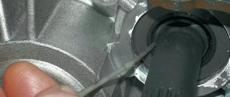
- Using a special puller, remove the bearing from its seat.
The removal procedure is accompanied by slight tapping of the part. The installation procedure is performed in reverse order.
Secondary shaft bearing
The only difference between the procedures is the use of different sized bearings.
Replacing the intermediate shaft bearings
The procedure is carried out similarly with the intermediate element. Using yews and a special puller
Operation diagram of a five-speed gearbox
The five-speed gearbox is based on a four-speed gearbox, so the torque transmission patterns from the input shaft to the secondary in all forward gears, with the exception of fifth gear and reverse, are similar to those of a four-speed gearbox. That is, the torque from the engine crankshaft is transmitted through the clutch to the input shaft 1 and through the constant mesh gears 3 and 39 to the intermediate shaft. The intermediate shaft gear block has constant engagement with gears 7, 8, 11 of the third, second and first gears of the secondary shaft. Therefore, they rotate from the intermediate shaft both when the gear is engaged and when the gear is disengaged. In addition, a block of 28 gears rotates together with the intermediate shaft, from the large ring of which the rotation is transmitted to gear 17 of the fifth gear. Since gears 7, 8, 11, 17 are freely mounted on secondary shaft 2, when the gear shift lever is in neutral position, none of these gears transmits torque to the secondary shaft. When starting the car and overcoming difficult sections of the road, 1st gear is engaged (see diagram of the movement of gear shift lever 16). In this case, the sliding clutch 9, engaging with the synchronizer ring of the first gear gear 11, connects the hub 32 with the gear 11. The torque from the gear 11 through the clutch 9 and the hub 32 is transmitted to the secondary shaft 2. The transmitted torque increases in accordance with the transmission number of first gear. With further acceleration of the car, they shift from first gear to second. In this case, clutch 9 connects hub 32 to the ring gear of second gear gear 8, and the torque from gear 8 is transmitted through clutch 9 and hub 32 to the secondary shaft. The amount of torque is slightly reduced and, compared to direct transmission, will be increased by 2.1 times, the vehicle speed increases. When switching to third gear, the sliding clutch 5 of another synchronizer connects hub 37 with the crown of gear 7. Torque is transmitted from gear 7 through clutch 5 and hub 37 to secondary shaft 2. The magnitude of the torque decreases slightly, and the speed increases. When the fourth gear is engaged, clutch 5 engages with the gear ring 4 of the drive shaft, i.e., it directly connects the primary and secondary shafts of the gearbox. In this case, the rotation speed of the primary and secondary shafts will be the same and the amount of torque does not change. This transmission is called direct. When fifth gear is engaged, sliding clutch 14 connects hub 13 to the ring gear of gear 17. Torque will be transmitted from input shaft 1 through constant mesh gears 3 and 39 to the intermediate shaft. From it to the block of 28 gears and from the large crown of the block to the driven gear 17 of the fifth gear, then through the clutch 14 and hub 13 to the secondary shaft 2. In this case, the amount of torque will be minimal and the speed will be maximum. Reverse gear is engaged by moving the gear lever to the right, then pushing it down and moving it backwards along the vehicle's path. In this case, the reverse intermediate gear 27 engages with the small rim 26 of the gear block and with the rim of the reverse gear 12. When the intermediate gear 27 moves, the head of the rod presses on the ball of the switch rod 25 and recesses it. The reverse light circuit closes and signals in white that reverse gear is engaged. When the gear is engaged, when the secondary shaft 2 rotates, rotation is transmitted to the drive gear 20 when the speedometer is turned on. From it, rotation is transmitted to the driven gear of the speedometer drive and through a pair of helical gears to the speedometer cable drive shaft; the cable operates the speedometer. The gearbox parts are lubricated with gear oil, which is poured in an amount of 1.55 liters. When shafts and gears rotate, oil mist is generated. Oil flows through radial holes in driven gears 7, 8, 11 and 17 to the landing belts of the secondary shaft on which these gears are located. Due to the grooves, an oil film is formed on these belts, preventing direct contact between the metal surfaces of the gears and the shaft. The tightness of the gearbox housing is ensured by the oil seals of the primary and secondary shafts and sealing gaskets that are installed between the housing and the lower and rear covers. To reduce the oil pressure on the secondary shaft oil seal, an oil deflector washer 19 is installed on the shaft. The axial forces arising when transmitting torque through helical gears are perceived by the ball bearings of the shafts, which are fixed in their sockets with adjusting rings (the intermediate bearing of the secondary shaft with a locking plate), and on the shafts with spring washers and locking rings. The simple design of the gearbox, constant-mesh helical gears and synchronizers ensure durable and quiet operation of the gearbox. Its maintenance is kept to a minimum: checking the level and changing the oil.
Second phase. Disassembly and direct repair
Before starting repairs, it is necessary to clean the outer part of the gearbox using a brush and rinse it with kerosene. Now we can begin. The fork that disengages the clutch and the release bearing in the clutch is removed from the gearbox. We separate the secondary shaft from the propeller shaft and disconnect the edge of the EF from the secondary shaft. Then we separate the entire power unit block. We remove the speedometer drive.
- It is necessary to remove the cuff from the ball joint;
- Unscrew the three fastening nuts that secure the shift lever to the rear of the crankcase;
- The sealing gasket is removed from the stud;
- Using a socket-type wrench, loosen the nuts that secure the supports (bracket) of the exhaust pipe;
- This support is removed and the bolt that is located between them is removed;
- The nuts that secure the cover from the back must be unscrewed using a thirteen wrench;
- Using a 10mm socket wrench, unscrew the 10 nuts securing the bottom cover of the box;
- After which the cover is removed and the gasket is removed from under it;
If the nuts are turned out at the same time as the studs, it would be wise to use fixing glue. Before applying it to threaded holes and studs, they must first be washed with solvent. After completing this procedure, you need to take a 30mm wrench and unscrew the nut that secures the back cover. You can see it inside the crankcase itself.
Then you need to remove the back cover. Important! It is necessary to put in second gear. We take out the plug made of plastic, which is located on the back of the lid; using tweezers or tweezers, you need to remove the thrust ring. And finally, we take out the secondary shaft ring, which is located inside.
Sometimes it becomes necessary to replace bearings. So, replacing the VAZ 2107 gearbox bearings will be carried out according to the following algorithm:
- The retaining ring is removed from the holder located outside;
- Using a puller, the ring is removed;
- Then we take out the old bearing and insert a new one, after which we put the retaining ring in place.
This completes the disassembly of the VAZ2107 gearbox. Now you can replace all unusable parts.
Classic 7s are still popular among Russians, despite the abundance of inexpensive foreign cars. Some criticize the Zhiguli car, others call it a “Russian Mercedes”. Any car, even if not the most prestigious one, must be well maintained - then it will drive properly for many years to come, as practice shows.
Repair of VAZ 2107 gearbox
— 2000 rub.
Exchange of VAZ 2107 gearbox with installation
— 4000 rub.
Sale of used gearbox after refurbishment
— 6000 rub.
The “seven” gearbox does not cause serious complaints from owners. It comes in two types - four- and five-stage. The presence of noise is its main disadvantage, and many drivers get so used to it that they do not pay attention to it and continue to use the car. This is the wrong approach: a “noisy” gearbox is not only a feature of its design, but also a sign that the VAZ 2107 gearbox will need repair
.
Typical causes of gearbox malfunctions
Uncharacteristic noise indicates that there is:
- wear of bearings, gears or synchronizers;
- displacement of shafts along the axes;
- oil leak.
Diagnostics at a car service center will reveal the cause of the noise. Most likely, parts will need to be replaced and oil added to determine the cause of the leak.
Heavy gear shifting indicates:
- clutch malfunction;
- the shift lever hinge requires surface cleaning;
- deformation of the shift lever.
Knocks out gears:
- synchronizer spring failure;
- wear of the retainer springs, balls, coupling or synchronizer ring gear;
- wear of the rod sockets blocking the rings.
Causes of oil leakage:
- loosening of the crankcase cover;
- wear of seals;
- wear or damage to the sealing gasket.
Specific causes can only be determined after checking with diagnostic equipment. Based on the results of the troubleshooting, the car service specialist will determine what kind of repair of the 2107 gearbox
required.
Do-it-yourself repairs are not the best option for caring for your car. Many car owners consider themselves specialists and try to save money on car service. The result of such savings may be complete failure of the gearbox. This is a solvable problem: you can exchange the VAZ gearbox
for new or refurbished. But it will cost more.
The exchange option is not so bad and can bring the “Seven” back to life when the box is not at all repairable or the owner does not have time to wait for repairs - the car is needed urgently.
In our workshop you can not only determine the causes of gearbox malfunctions and repair them, but also supply new, high-quality ones in a short time and at an affordable price. We employ experienced craftsmen and have all the necessary equipment.
Removing the gearbox from a VAZ 2106, 2107 car.
Dismantling work, disassembling the gearbox and repair work is a complex and time-consuming job that requires the necessary conditions and tools
and
knowledge
.
The car should be placed on a viewing hole, and the wires from the battery should be disconnected.
Step transmission. Device and principle of operation
Mechanical box
(switching)
gears
(manual transmission or manual transmission) - a type of gearbox, a mechanism designed for stepwise change of gear ratio, in which gear selection is carried out manually by the operator (driver). It is named so because all of its main functionality is implemented exclusively through mechanical devices, without the use of hydraulic or electrical elements (unlike hydromechanical or electromechanical transmissions, which contain, respectively, hydraulic and electrical elements in their design).
Simple stepped gearboxes are widely used in vehicle transmissions, as they are simple in design and reliable in operation. The following requirements apply to gearboxes of this type:
The requirements determine the rational design of the gearbox and its individual parts.
Most of the wheeled vehicles studied are equipped with five-speed three-way simple gearboxes (five forward speeds and one reverse gear). The number of “strokes” of the gearbox corresponds to the number of moving elements with the help of which certain gears are engaged.
Repair
Repair of the five-speed gearbox of VAZ 2106, 2107 cars is carried out in cases of increased noise, heavy, unclear gear shifting. These factors indicate that the box requires repair work. There are many reasons that influence the incorrect operation of the gearbox:
- wear of the shift lever hinge and its holes is manifested by spontaneous gear disengagement and difficult shifting;
- wear of bearings, gear teeth or synchronizers; the absence or insufficient amount of lubricant is manifested by increased operating volume and the presence of extraneous noise; various types of deformation of parts;
- loosening of the crankcase, covers, wear of oil seals and gaskets lead to leakage of transmission oil, which can lead to significant damage to the gearbox.
To identify the causes, a complete disassembly of the gearbox is required.
After diagnosing and determining the cause of the gearbox failure, non-functioning components and parts should be replaced.
It also wouldn’t hurt to replace the box components that are still working, but with a high level of wear. We inspect:
clutch, crankcases, cover for cracks, surface roughness, holes, dents, etc. Minor chips can be removed with sandpaper. Severe damage indicates replacement of defective parts. It is recommended to check the fit under the bearings for wear and mechanical damage. If damaged, it is recommended to replace the crankcases.
Check the forks and shift rods, oil seals, bearings of the VAZ 2108 VAZ 2109 box. If dents, roughness, or holes under the clamps are observed, it is recommended to replace the rods. It is necessary to check the condition of the gear shift forks. The forks are concave and worn out and must be replaced.
Oil leakage through the seals and wear of the working edge indicate the need for urgent replacement of the unit. The appearance of the bearings of the VAZ 2106, the shells of the treadmills and the rolling body of the VAZ 2107 box, traces of pressure from the rolling bodies, damage to the bearing separators - is characterized as a defect and it is recommended to replace all components, as well as jammed gaskets with damage.
Gearbox device
The gearbox (abbr. gearbox or gearbox) is designed to change the torque transmitted from the engine crankshaft to the drive wheels, to move the car in reverse and to long-term disconnect the engine from the transmission while the car is parked and when it is coasting.
Mechanical transmission device (clickable). A manual gearbox is a gearbox in which gear selection and engagement are carried out manually, mechanically. A manual transmission is no longer the most common type of transmission used on cars today. However, it still remains quite in demand due to its reliability, simplicity of design and maintainability.
The list of works includes the following actions:
- removing the locking sleeve from the plane of the assembly by inserting a screwdriver into the locking hole of the sleeve;
- dismantling the lever rod; dismantling the damper bushing; release the fixing bolts of the cover, which are located on the bottom of the car and remove the lever with the seal;
- disconnect the pipe from the exhaust system;
- dismantling the starter and gradually disconnecting the lamp wire (reverse);
- dismantling the cardan transmission and flexible shaft;
- releasing the clutch housing bolts using a socket wrench;
- disconnecting the clutch from the block;
- Carefully remove the PP box.
Disassembly of the box occurs in a strictly defined sequence.
Mechanical transmission device
Transmission operation diagram: 1 - input shaft; 2 — shift lever; 3 - switching mechanism; 4 - secondary shaft; 5 - drain plug; 6 — intermediate shaft; 7 - crankcase. Structurally, the manual transmission consists of the following elements:
Clutch
The clutch is an integral component of a manual transmission, which disconnects the engine and gearbox at the moment of gear shifting without consequences for the units. To put it simply, the clutch turns off the torque. When the clutch pedal is depressed, the engine and the wheels of the car rotate separately from each other.
The clutch is designed to neatly connect the motor and wheels. It consists of two disks, one of which is connected to the engine, the second to the wheels. When the clutch pedal is released, the discs are pressed and begin to rotate together. This is why smooth release of the pedal is important.
Gears and shafts
In standard manual transmissions, the shaft axes are located parallel, and gears are located on them. The drive (primary) shaft is connected to the engine flywheel through the clutch basket; the longitudinal projections located on it move the second clutch disc and transmit torque to the intermediate shaft through a rigidly fixed drive gear.
In the shank of the drive shaft there is a bearing, to which the end of the secondary shaft is adjacent. The absence of a fixed connection makes it possible for the shafts to rotate independently of each other in different directions and at different speeds.
The driven shaft has a whole set of different gears, both rigidly fixed and freely rotating.
Synchronizers
The angular velocities of the primary and secondary shafts are equalized with the assistance of the synchronizer and a stage change becomes possible. Synchronizers provide more gentle operation of the gearbox and reduced noise.
When the driver engages the gear, the clutch is fed towards the desired gear. During movement, the force is transferred to one of the coupling locking rings. Due to the different speeds between the gear and the clutch, the conical surfaces of the teeth interact through friction. She turns the locking ring against the stop.
The teeth of the latter are installed against the teeth of the coupling, so subsequent displacement of the coupling becomes impossible. The clutch engages without resistance with the small ring on the gear. Due to this connection, the gear is rigidly locked with the clutch. This process is carried out in a fraction of a second. One synchronizer usually provides two gears.
Checkpoint structure
Typically, modern cars, as far as the gearbox is concerned, have steps. Most often this is a manual transmission. They have several gears. The gearbox includes four to five speeds, not to mention reverse.
Changing speeds is possible due to the movement of gears, they cling to each other, as a result, blocking occurs due to the forward movement of the device, which serves to synchronize the torque and the wheel. The gears can be controlled manually when a manual transmission is used, or this action occurs automatically when the automatic transmission is operating.
Old gearboxes had three- and four-speed ranges, but modern analogues can boast 8 speeds, or even higher. The calculation of the number of gears depends on the type of motor and other factors.
Let's look at what the gearbox includes, if we talk about the elements in more detail.
The first unit that makes everything come together is the body. This includes various transmission components, such as gear blocks, overrunning clutches and a reverse block. The clutch device is located next to the flywheel, which is mounted on the motor.
Given the principle of operation, the gears rub against each other a lot during operation of the gearbox, which means that they need plenty of lubrication. Therefore, the crankcase must be filled with oil to a certain level. The gearbox also has various types of devices, they are equipped with bearings, each of them is located in the crankcase, each block has several gears, the number of teeth of which is different.
The next part we will talk about is synchronizers
For any car, it is important that the gearbox be smooth, without unnecessary noise, shock, or vibration, therefore synchronizers equalize the operation of gears that have constant rotation
Correct calculation of gear ratios allows the gearbox to convert engine torque and accurately distribute it to the drive axles. This technology has long been used by leading automakers.
In order to change gear in the gearbox, the driver depresses the clutch and moves the rocker lever to the desired position.
Everything is done in such a way that even with a strong desire to engage two gears at the same time, this is impossible to do. On the other hand, thanks to the rocker lock, the gears themselves cannot be switched or switched off.
Operating principle of manual transmission
The essence of the operation of a manual transmission is to create connections between the primary and secondary shafts by varying gears with different numbers of teeth, which adapts the transmission to the constantly changing circumstances of the vehicle's movement.
This power unit provides the necessary operating modes of the engine by changing the number of revolutions, changing the transmitted force to the drive wheels. Accordingly, when the number of revolutions decreases, the transmitted force decreases, and when the number of revolutions increases, it increases. This is necessary when maintaining the required engine operating mode when starting to move, reducing speed or accelerating.
Twin-shaft gearbox: device and principle of operation
In such transmissions, torque is transmitted from the input shaft gears to the driven gears.
The drive shaft is connected to the motor through a flywheel, and the driven shaft transmits torque to the front wheels. They are located in parallel. The main gear drive gear is firmly fixed on the secondary shaft. Between the gears there are synchronizer clutches.
To reduce the size of the unit and to increase the number of stages, up to three secondary shafts are installed, each of them has a main gear gear, which constantly interacts with the driven gear.
The main gear and differential transform the torque of the secondary shaft to the drive wheels of the machine.
Three-shaft gearbox: device and principle of operation
Bearings located in the housing ensure rotation of the shafts.
Each shaft has a set of gears with a different number of teeth. The drive shaft is adjacent to the engine through the clutch basket, the driven shaft is connected to the cardan shaft, and the intermediate shaft transmits torque to the secondary shaft.
There is a drive gear on the input shaft, which spins the intermediate gear with a firmly fixed set of gears located on it. The driven shaft has its own set of gears moving along splines.
Between the gears of the secondary shaft there are synchronizer clutches, which equalize the angular speeds of the gears with the revolutions of the shaft itself. The synchronizers are firmly attached to the shafts and move longitudinally along splines. On modern manual transmissions, such clutches are located at each stage.
Advantages and disadvantages of manual transmission
| Advantages | Flaws |
| The cost and weight of the box is lower compared to other types of gearboxes | Less comfort level for the driver compared to other gearboxes |
| High acceleration dynamics, fuel efficiency and efficiency | Tiring gear shifting process for the driver |
| High reliability due to simplicity of design | The need to periodically replace the clutch |
| Simple and inexpensive maintenance | Lower vehicle smoothness compared to other types of gearboxes |
| Possibility of more efficient off-road driving | In case of improper operation, increased loads on the internal combustion engine |
How to use a manual transmission
Using a car with a manual transmission has some features that a car enthusiast needs to know.
First, this is the sequence of actions when starting the machine:
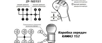
Secondly, the switching pattern for manual transmission. It is most often located on the outer part of the lever handle. When changing gear, it is recommended to focus on the tachometer. You can switch to a higher gear by spinning the engine speed to 1500–2000 rpm in the case of a diesel engine and up to 2000–2500 rpm in the case of a gasoline engine.
Thirdly, the gear shift process. It consists of several stages:
Fourthly, regularly checking the fluid level and replacing it according to the manufacturer’s instructions will extend the life of the manual transmission.