Step transmission. Device and principle of operation
A manual gearbox
(
transmission
or manual transmission) is a type of gearbox, a mechanism designed for stepwise change of gear ratio, in which gear selection is carried out manually by the operator (driver). It is named so because all of its main functionality is implemented exclusively through mechanical devices, without the use of hydraulic or electrical elements (unlike hydromechanical or electromechanical transmissions, which contain, respectively, hydraulic and electrical elements in their design).
Simple stepped gearboxes are widely used in vehicle transmissions, as they are simple in design and reliable in operation. The following requirements apply to gearboxes of this type:
The requirements determine the rational design of the gearbox and its individual parts.
Most of the wheeled vehicles studied are equipped with five-speed three-way simple gearboxes (five forward speeds and one reverse gear). The number of “strokes” of the gearbox corresponds to the number of moving elements with the help of which certain gears are engaged.
The five-speed gearbox has 3 shafts:
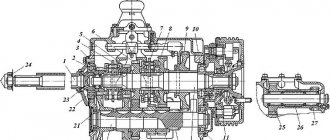
The shafts are mounted on rolling bearings in the crankcase, which also serves as an oil reservoir, with filler, inspection and drain holes, as well as a ventilation device. An axle with a block of 7 3X gears mounted on bearings is fixed in the crankcase. Gear 17 is integral with the drive shaft and is in constant mesh with the corresponding gear 16 of the intermediate shaft, as a result of which the intermediate shaft receives rotation from the drive shaft with a constant gear ratio, which is determined by the ratio of the number of teeth of the driven gear to the number of teeth of the drive. The gears of the driven shaft (except for the 1st gear and 3rd gear) are in constant mesh with the corresponding gears of the intermediate shaft, but are installed on the driven shaft freely (they can rotate relative to the shaft, but not move along it). Therefore, although the intermediate shaft will rotate when the engine is running and the clutch is engaged, rotation will not be transmitted to the driven shaft, and therefore to the drive wheels of the propulsion unit (neutral position).
Rice. Five-speed gearbox diagram
Gear engagement is ensured by two synchronizers - 2 and 3 and gear 4 of 1st gear and 3rd gear, which are mounted on the driven shaft on splines and can move along the shaft. The gear shift mechanism contains a control lever, rollers (rods) with forks that move synchronizers and carriage 4, clamps and a safety locking device installed in the gearbox cover. Synchronizers have toothed rims, which, when gears are engaged, engage with the corresponding toothed rims of constant-mesh gears, which ensures the transmission of torque to the driven shaft and further to the driving wheels of the propulsion device. The gear ratio between the intermediate and driven shafts is determined by the ratio of the number of teeth on the driven shaft gear to the number of teeth on the intermediate shaft gear. The gear ratio between the drive and driven shafts, i.e., the total gear ratio of the gearbox, is the product of two gear ratios, one of which is between the drive and intermediate shafts, and the other between the intermediate and driven shafts.
The higher the gearbox ratio, the greater the torque transmitted to the drive wheels for the same engine torque, and the vehicle speed is correspondingly lower. In 1st gear, when the gear ratio is the largest, the vehicle is usually started from a standstill and initially accelerated, as well as driving in particularly difficult conditions. Engaging 1st gear is ensured by moving gear 4 forward and engaging it with gear 8 of the intermediate shaft. As driving conditions improve, higher gears with smaller gear ratios are switched on, when a significant increase in traction force on the drive wheels is not required, and the vehicle speed increases.
The highest gear in the above diagram of the gearbox is V gear, which is obtained by connecting the drive shaft 1 and driven shaft 5 using the drive shaft gears and synchronizer 2; the gear ratio in this case is equal to one (direct transmission).
When the vehicle is moving in direct gear, the intermediate shaft of the gearbox rotates idle.
Reverse motion is ensured by moving gear 4 back and engaging it with one gear of block 7 3X. The other gear of the block is in constant mesh with gear 11, rigidly connected (secured with a key) to the intermediate shaft.
Torque is transmitted from the drive shaft to the driven shaft through the following parts:
For smoother engagement and quieter operation, constant mesh gears are usually helical. The angles and direction of inclination of the teeth on various pairs of gears are selected so that the axial forces on the shafts are minimal. These axial forces are usually carried by a radial ball bearing mounted at one end of the shaft. The other end of the shaft rests on a cylindrical roller bearing. This prevents the occurrence of additional stress in the bearings as a result of thermal elongation of the shafts. The bearing housings are closed with covers with sealing gaskets. If the end of the shaft comes out, seals are installed in the covers to prevent lubricant from leaking out. Oil drainage grooves on the shafts also contribute to this.
Principal kinematic diagrams and operation of gearboxes with fixed shaft axes
The design of the gearbox is determined by the purpose of the tractor, the nominal traction force (traction class), the nature of the operating loads and the indicators of the complexes of aggregated machines - implements. An analysis of modern gearbox designs shows that most of them are composite combinations of simpler two-shaft and three-shaft gearboxes, the diagrams of which are given below.
It should be noted that in all gearbox diagrams under consideration, control carriages or locking clutches are shown in their neutral position (in neutral gear).
The simplest diagram of a two-shaft gearbox (Fig. 4.2, a) with a break in the power flow when shifting gears, consists of a primary shaft 1 and a secondary 9. Power from the engine is usually supplied to shaft 1 through the clutch, and the output end of shaft 9 in most cases has a drive conical gear 8 of the central transmission of the transmission. On the splines of the input shaft 1, a movable double-crown carriage 2 is installed to obtain the second (to the left in the direction of the arrow) and a third (to the right of the arrow) gear and a single-crown carriage 4 to obtain the first (to the left of the arrow) gear and reverse (to the right of the arrow). The right protruding splined shank 5 can drive the dependent PTO. On the secondary shaft 9, the driven gears of the forward gears are fixedly mounted: the first 11, the third 12 and the second 13, with which the gear rings of the carriages are engaged to obtain the required gear, and the driven gear 10 of the reverse gear.
Rice.
4.2. Principal kinematic diagrams of the gearbox: a - two-shaft. 6 - three-shaft, c - three-shaft with transverse shafts The movement of the carriages along the splines of the primary shaft 1 is carried out by a separate lever-traction system of manual control of the gearbox, which allows only one pair of gears to be locked in mesh, providing the required gear ratio.
Gears and shafts are placed inside the gearbox housing 3, in the holes of the walls and partitions of which the corresponding bearings for shaft supports or additional axles are installed. Domestic tractors mainly use cast iron gearbox housings. In foreign designs, lighter and stronger casting materials (aluminum alloys) are also widely used.
The input shaft supports are usually radial ball bearings, loaded mainly by radial forces. The secondary shaft supports are more complex, since in most cases they perceive not only the radial forces acting on them when transmitting torque, but also the axial force acting from the bevel pair of the central gear.
To obtain reverse gear, an additional gear transmission is introduced between the gearbox shafts, changing the direction of rotation of its secondary shaft while maintaining constant rotation of the primary shaft. This can be a gear or a block of two gears of the same or different diameters, which are in constant mesh with a driven gear mounted on the secondary shaft. In the gearbox scheme under consideration, reverse gear is obtained when the carriage 4 is brought into contact with the gear block 6, which is in constant engagement with the driven gear 10 of the secondary shaft. Block b is installed on the bearings of the fastening axis 7.
This kinematic diagram of a two-shaft gearbox shows an almost minimum number of gears - three forward and one reverse. In practice, the number of gears does not exceed six, since as they increase, the length of the shafts and their deflection when transmitting torque increases. This leads to disruption of gear engagement and deterioration of bearing units, and ultimately to reduced gearbox durability.
The rubbing parts of this gearbox are lubricated by oil poured into its crankcase and then sprayed onto the rims of the rotating driven gears when the tractor moves. To lubricate gearbox parts during stationary operation of the MTA, when the secondary shaft is motionless, in a number of designs special oil-spraying gears are used, kinematically connected to the primary shaft. One of these options is shown in the given gearbox diagram, where the driven oil-sprinkling gear 14, freely rotating on shaft 9, has a constant drive from the drive gear 15 of shaft 1.
The advantages of two-shaft gearboxes are: structural simplicity and high mechanical efficiency, since only one pair of gears is involved in the transmission of power. The disadvantages are the inability to obtain more than 5-6 forward gears due to increased shaft deflection, and a small range of gear ratios limited by the center distance of the shafts. As a result, they currently have limited use as independent gearboxes, but are often used as one of the gearboxes of a composite gearbox. Moreover, very often they are performed with constant mesh gears (see Fig. 4.1.6 - d).
The simplest diagram of a three-shaft gearbox (Fig. 4.2.6) with a break in the power flow when switching and with a longitudinal arrangement of shafts consists of coaxially located primary 1 and secondary 8 shafts and an intermediate shaft 14. Shafts 1 and 14 are connected by a pair of cylindrical gears of constant mesh - drive 2 and driven 15, forming the gear ratio of the first gearbox stage. At the end of the shaft 8, the driving bevel gear 9 of the central transmission of the transmission is usually installed or made integral with it.
The forward drive gears 13 are rigidly fixed to the intermediate shaft 14. The gear rims of the driven carriages of the secondary shaft 8 engage with them, thereby forming the gear ratios of the second stage of this gearbox. The drive gear 12 of the reverse gear is also fixed to the intermediate shaft 14, which is in constant engagement with the single-ring “parasitic” gear 10.
On the splines of the secondary shaft 8 there are standard single-crown 7 and double-crown 6 carriages and a combined single-crown carriage 4 with a gear locking half-coupling 3. The latter, when moving the carriage 4 to the left, engages with the gear half-coupling at the end of the primary shaft, thereby forming a direct transmission of power from shaft 1 to vase 8. The front bearing 16 (usually roller) of shaft 8 is installed in the bore of the end of shaft 1 and is loaded only by radial forces. The remaining shaft supports are installed in the holes of the walls or special partitions of the crankcase 5, similar to the mounting of the shafts of a two-shaft gearbox. In some designs of three-shaft gearboxes, in order to eliminate the cantilever mounting of gear 2 and facilitate the operation of the front bearing 16 of shaft 8, direct transmission is eliminated and separate supports are provided for the end of shaft 1 and the beginning of shaft 8, especially since on tractors direct transmission does not apply to their main (working) range.
In this kinematic scheme of a three-shaft gearbox, you can get five forward gears (including direct) and one reverse gear.
The gearbox parts are lubricated by splashing oil poured into its crankcase onto the gears of the intermediate shaft 14, which always rotates when the engine is running and the clutch is engaged, regardless of the operating mode of the MTA. The splined shank 11 of the shaft 14 can be used as a drive for the dependent PTO.
The simplest diagram of a three-shaft gearbox with a transverse shaft arrangement, complete reversal of all gears and a structural arrangement in the common housing of the tractor rear axle is shown in Fig. 4.2,c.
The most interesting element of the circuit is the gear reverse mechanism, which allows the intermediate shaft 6 to rotate in different directions with a constant direction of rotation of the primary shaft 1. It consists of a driving bevel gear 2, which is in constant mesh with two identical driven bevel gears 3 and 4, freely mounted on shaft 6 and rotating in opposite directions. On the hubs of these gears there are ring gears similar to the ring gear 17 of shaft 6, on which a movable gear coupling 8 is installed, blocking the shaft with any of the above gears. The diagram shows the position of clutch 8 for moving the tractor forward. When shaft 6 is connected to gear 3, the tractor will move backward. Clutch 8 is moved by a separate reverse control lever.
The connection of the single-crown 5 and double-crown 18 carriages with the driven gears 16 of the secondary shaft 11 is similar to that discussed above.
In similar gearboxes with complete reversal of all forward gears, sometimes, as shown in the diagram, one separate reverse gear is performed. It is carried out by moving the carriage 5 into engagement with the “parasitic” gear 9, which is in constant engagement with the reverse driven gear 10 on shaft 11. The use of this gear is explained by the convenience of controlling the gearbox with one lever for both forward and reverse gears. With a fully reversible gearbox without an additional reverse gear, in order to reverse, the tractor driver has to simultaneously manipulate two control levers - reverse and gearbox, which causes a certain inconvenience.
The arrangement of transversely located shafts 6 and 11 in the common transmission housing 7 facilitates the execution of the central transmission by spur gears - drive 12 and driven 13, mounted on the differential housing 14. The splined shank 15 of shaft 11 can be a side drive of the synchronous PTO.
It should also be noted that the bevel pair that forms the gear ratio of the first stage of the gearbox is facilitated; this is a more stable load and speed regime, which makes it possible in most cases to avoid periodic adjustments of the gear meshing before their final rejection.
Gearbox parts are lubricated by splashing oil located in the housing.
This type of gearbox is used on light wheeled universal tractors, which, due to the nature of their work, must be able to move in reverse for a long time and under different traction loads.
The advantages of three-shaft gearboxes are: - a significantly larger range of gear ratios than two-shaft gearboxes, since the main working gears always involve two pairs of gears; — high efficiency in direct (transport) transmission; — no need for an oil-spraying pair of gears; — structurally simpler design of the central gear with a cylindrical pair of gears in three-shaft gearboxes with transverse shafts than in a bevel pair of two-shaft gearboxes.
The disadvantages of three-shaft gearboxes are: - lower efficiency in working gears, since two pairs of gears are simultaneously engaged, instead of one in a two-shaft gearbox; — impossibility of obtaining more than 5-6 forward gears due to increased shaft deflection; — increased wear of the front support bearing of the secondary shaft, located in the bore of the end of the primary shaft when the tractor is operating in the main working gears. When the direct drive is engaged, the specified bearing does not rotate, but the tractor operates in this transport gear, as a rule, no more than 12... 15% of its total operating time.
Composite CPs have block diagrams shown in Fig. 4.3. In the diagram shown in Fig. 4.3a, in front there is a gearbox P with two gears (n=2) for selecting ranges of tractor operation, and behind it is the main gearbox with four forward gears within the selected range and one reverse (n3x=1) The total number of forward and reverse gear is determined by the product of the numbers of the corresponding types of gears in the gearbox and gearbox: eight forward gears (n nx = 8) and two reverse gears (n3x = 2).
Depending on the layout of the transmission in a composite gearbox, the main gearbox can be installed in front, and behind it the output gearbox P (Fig. 4.3.6), but the result will be the same as in the first diagram (nnx=8; n3x=2) .
In the diagram shown in Fig. 4.3c, gearbox P has nnx=3 and n3x=1. The total number of forward gears is nnx=12, and reverse gears n3x=4. In the diagram shown in Fig. 4.3d shows an example of using two gearboxes P1 (nnx=3;n3x=1) and P2 (n=2) simultaneously, which makes it possible to obtain nnx =24 and n3x=8.
Rice. 4.3. Structural diagrams of composite CNs
Elementary kinematic diagrams of composite gearboxes and the layout of their main components are presented in Fig. 4.4. In Fig. 4.4a shows a gearbox diagram consisting of an input two-stage gearbox A, made according to a three-shaft scheme, and the main gearbox B, made according to a two-shaft scheme with three forward gears and one reverse. In this scheme, the secondary shaft 1 of gearbox A is the front end of the primary shaft of box B, and the corresponding secondary shaft 2 of box B and the intermediate shaft 3 of gearbox A have supports in the walls of the gearboxes.
In this scheme, you can get six forward and two reverse gears. Since gearbox A is made with an acceleration gear, the main working gears of the composite gearbox are carried out when the direct gear of the gearbox is engaged, so that only one pair of gears of gearbox B is engaged, which ensures the high efficiency of the working gears. To obtain gears with less traction on the tractor hook and transport ones in gearbox A, transmission is carried out through two pairs of gears.
Rice. 4.4. Kinematic diagrams of composite gearboxes
In Fig. 4.4.6 shows a diagram of a composite gearbox, made in one common housing 3, using three parallel shafts: primary 1, intermediate 6 and secondary 8. Shafts 1 and 6 are an input twin-shaft gearbox of gear ranges with constant mesh gears, locked by means of movable gears couplings 12. Gears 2 and 11 provide three forward gears, and gears 4, 5 and 7 provide reverse gears. Shafts 6 and 8 are also a two-shaft four-speed gearbox with constant-mesh gears 9, which are locked with shaft 8 by means of multi-plate friction clutches 10 with a hydraulic pressure mechanism. Consequently, in this composite gearbox scheme, twelve forward gears and four reverse gears can be obtained. In this case, within the established range, gear shifting is carried out without stopping the tractor.
As an example, consider the composite gearbox of MTZ-80/82 tractors (Fig. 4.5).
It has a two-stage reduction gearbox and a main gearbox, which provide 18 forward gears and four reverse gears. The main gearbox is nine-speed, consists of a primary1, intermediate 22 and secondary 12 shafts, as well as a shaft 25 of low gears and reverse gears located in the housing 11. The drive gear 13 of the central gear is installed on the secondary shaft 12. Inside the intermediate shaft 22 there passes the shaft 14 of the independent PTO drive.
The main gearbox has its own two-stage gearbox. It consists of a double-ring gear carriage 16, which can engage with the gear 7 of the secondary shaft or with the internal teeth of the gear 15, freely mounted on the intermediate shaft 22 and in constant engagement with the fixed gear 10 of the secondary shaft. The meshing of gears 16 and 7 produces the first gear stage, and the meshing of gears 16, 15 and 10 produces the second.
On the splines of the input shaft 1 there are movable gears - carriages 2, 3 and 4, which can engage, respectively, with gears 21, 19 and 18, fixedly mounted on the intermediate shaft 22, and provide three gear ratios. The torque is transmitted from the intermediate shaft through the first or second stage of the gearbox. As a result, the number of transmissions doubles. In the gearbox scheme under consideration (Fig. 4.5, d), gears from third to eighth are obtained according to the three-shaft gearbox scheme.
In first and second gears and reverse gears, the moment from the input shaft 1 to the secondary shaft 12 is transmitted through the low gear shaft 25. In this case, the moment from gear 4 through the double-ring gear 17, freely mounted on the intermediate shaft 22, is transmitted to gear 28, which is in constant engagement with the small rim of gear 17. Then from shaft 25 the moment is transmitted to the intermediate shaft 22 and through the gearbox to the secondary shaft 12. To obtain the first and second gears, the carriage 27 is engaged with the gear 19, and the two reverse gears with the intermediate gear 26. The latter is in constant engagement with the gear 20.
The ninth gear is obtained by engaging gear 4 with the internal teeth of gear 7 (direct gear). Gear shifting is performed by lever 8, which moves sliders 5, which are kept from spontaneous movement by clamps 6 in cover 9.
A reduction gearbox (see Fig. 4.5d), installed in front of the main gearbox, doubles the number of gears. It consists of two pairs of gears 29, 24 and 23 and a gear coupling 30. When the coupling is engaged with gear 24, the torque is transmitted without change (direct transmission); when engaged with gear 29, a reduced gear is obtained.
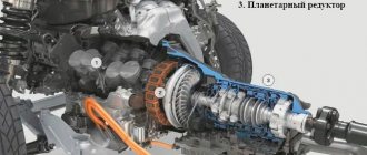
On MTZ-80/82 tractors, a two-stage planetary speed reducer can also be installed, allowing additional four low forward and four reverse gears.
Rice. 4.5. Composite gearbox of MTZ tractors - 80/82:
a - longitudinal section, b - cross section, c section along the shaft of low gears and reverse gears; d - kinematic diagram
Step transmissions
Mechanical step transmissions, unlike continuously variable ones, allow you to change the torque transmitted by the transmission to the drive wheels stepwise (stepwise). This is a significant drawback of this type of gearbox, which is compensated by the simplicity of their design, relative reliability and unpretentiousness. In addition, step transmissions can improve the dynamic qualities of the car (for example, during acceleration) and its efficiency. For these reasons, manual transmissions are now widely used in all types of cars and buses.
Types of manual transmissions
Step transmissions are classified according to several main characteristics:
They can be simple (shaft) and planetary, depending on the mobility of the geometric axes of their shafts.
Based on the number of shafts, simple gearboxes are divided into two-, three- and multi-shaft gearboxes.
Based on the number of stages (only forward gears are taken into account), gearboxes are divided into two-, three-, four-, five-speed and multi-speed.
According to the method of gear shifting, boxes can have movable gears, easy-to-use clutches and synchronizers.
According to the control method, gearboxes with direct, remote, semi-automatic and automatic control are distinguished.
According to the functions they perform, gearboxes are divided into main, divider and additional.
In addition to the above classification features, gearboxes are divided according to the number of strokes (planes of movement of the gear shift lever) into two-way and three-way. Three-speed gearboxes are two-way, which can currently only be found on cars of older brands, for example, GAZ-21.
On modern cars, simple, two- or three-shaft gearboxes are the most common. The number of gears in such boxes is usually 4…5. Increasing the number of gears on tractor-trailer vehicles, all-terrain vehicles and heavy-duty vehicles is carried out by installing a divider (multiplier) or an additional box (multiplier), which allows you to correspondingly increase the density of the row and expand the range of gear ratios. In this case, the total number of gears is equal to the product of the number of gears of the main gearbox and the additional one. Multi-speed gearboxes have 5 or 6 shafts and are therefore multi-shaft.
Most cars and trucks use direct-control gearboxes, in which the driver uses a lever to operate the elements of the gear shift mechanism (rods, forks, synchronizers or clutches) and engage the selected gear. With remote control, the force from the control lever to the gear shift mechanism is carried out through a system of rods and levers. Semi-automatic control elements are available in the control drive of the divider of KamAZ vehicles and the additional gearbox of the KrAZ-260 vehicle.
An automatic drive is not used to control step-by-step transmissions, and is usually used to control hydromechanical transmissions.
Planetary gearboxes, as a rule, are used as additional boxes in hydromechanical transmissions to enhance the converting properties of torque converters.
Kinematic diagrams of gearboxes
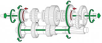
The structural, transformative and operational properties of gearboxes depend on its kinematic diagram. In Fig. 1 shows the most common kinematic diagrams of simple stepped gearboxes.
Any speed transmission is a gear reducer, in the housing 1 of which movable 8 or fixed 6, 7 gears are installed on the shafts. The input shaft 3 is called the input shaft, and the output shaft is called the secondary shaft. In a three-shaft gearbox, the third shaft 10 is called the intermediate shaft, and the primary and secondary shafts are located coaxially.
More about the three-shaft gearbox
Now let's return to the issue of the number of shafts, which we touched on in one of the sections above. Manual transmissions come in two- and three-shaft types . First, let's analyze the three-shaft “mechanics”, and then return to the two-shaft one. The main elements of the unit include:
- Primary (otherwise called drive) shaft;
- Intermediate shaft;
- Secondary (otherwise called driven) shaft with gear blocks with synchronizers;
- The crankcase in which the specified elements and the gear shift mechanism are located.
The drive shaft of a three-shaft manual transmission has splines that provide connection to the driven clutch disc. The torque received from the drive shaft is transmitted through matching gears that mesh with it.
The intermediate shaft is always parallel to the drive shaft. There is a block of gears on it, one of which must be engaged with the parallel gear of the drive shaft. As for the driven shaft, it is located on the same axis as the drive shaft. This is possible by using an end bearing on the drive shaft, which also includes the driven shaft. In this case, the gear block of the latter does not have a rigid fastening and can rotate freely . In this case, the gears of the intermediate and driven shafts, as well as the drive gears, are in constant mesh.
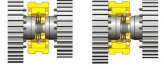
The reader probably guessed that synchronizers, otherwise called synchronizer couplings, are installed between the gears of the driven shaft. Their work is based on equalizing the angular speeds of gears due to friction forces. The synchronizers are fixed to the driven shaft, but they can move along the shaft thanks to a splined connection. In modern units, each gear is equipped with a synchronizer.
In a three-shaft gearbox, the connection mechanism is located directly in the unit housing. It is a combination of a control lever and the so-called. sliders with forks. The locking device also works in tandem with this mechanism. All mechanisms are controlled remotely, i.e. by manipulating the gear shift lever, which is located inside the car.
Gearbox device
The gearbox (abbr. gearbox or gearbox) is designed to change the torque transmitted from the engine crankshaft to the drive wheels, to move the car in reverse and to long-term disconnect the engine from the transmission while the car is parked and when it is coasting.
Mechanical transmission device (clickable). A manual gearbox is a gearbox in which gear selection and engagement are carried out manually, mechanically. A manual transmission is no longer the most common type of transmission used on cars today. However, it still remains quite in demand due to its reliability, simplicity of design and maintainability.
Transmission: types of gearboxes
As you know, the gearbox is one of the most important components of a car, responsible for transmitting torque from the engine crankshaft to the drive wheels. Modern cars are equipped with manual or automatic transmission.
All types and types of gearboxes have differences in operation, design and functionality. In this article we will look at what types of manual transmissions and types of automatic transmissions there are, as well as the main features of various types of transmissions.
Mechanical transmission device
Transmission operation diagram: 1 - input shaft; 2 — shift lever; 3 - switching mechanism; 4 - secondary shaft; 5 - drain plug; 6 — intermediate shaft; 7 - crankcase. Structurally, the manual transmission consists of the following elements:
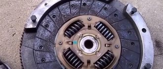
Clutch
The clutch is an integral component of a manual transmission, which disconnects the engine and gearbox at the moment of gear shifting without consequences for the units. To put it simply, the clutch turns off the torque. When the clutch pedal is depressed, the engine and the wheels of the car rotate separately from each other.
The clutch is designed to neatly connect the motor and wheels. It consists of two disks, one of which is connected to the engine, the second to the wheels. When the clutch pedal is released, the discs are pressed and begin to rotate together. This is why smooth release of the pedal is important.
Gears and shafts
In standard manual transmissions, the shaft axes are located parallel, and gears are located on them. The drive (primary) shaft is connected to the engine flywheel through the clutch basket; the longitudinal projections located on it move the second clutch disc and transmit torque to the intermediate shaft through a rigidly fixed drive gear.
Operating principle and design of a two-shaft gearbox
Twin-shaft mechanics includes:
- Shafts: driving and driven;
- Gears of both shafts;
- Main gear;
- Differential;
- Synchronizers;
- Speed shift mechanism;
- Housing or crankcase.
This type of box does not have an intermediate shaft. The drive and driven shafts are parallel to each other. The torque from the gears of the primary shaft is transmitted to the same parts of the secondary shaft.
Thanks to the absence of an intermediate shaft, it was possible to significantly reduce the weight and size of the transmission. Therefore, a two-shaft box is installed on cars and some motorcycles. To optimize operation, it is equipped with a larger number of gears than a three-shaft one. But this feature led to a decrease in efficiency.
The shaft gears rotate freely and actively interact. Synchronizer couplings are placed between them. The drive gear from the main gear is securely fixed on the driven shaft. She interacts with the slave.
Many transmissions of this type have multiple output shafts. All have such a drive gear. The number of driven shafts does not exceed three. It depends on the design and brand of gearbox.
The torque from the driven shaft is transmitted through the differential and the main gear to the driving wheels of the car. However, sometimes the wheels can spin at different speeds. For example, this happens if one of them hits a slippery surface.
The mechanism that is responsible for shifting gears is placed outside the box body. Rods or cables can be used to connect it to the transmission. Modern cars usually have cable manual transmissions.
The gear shift mechanism consists of:
- Speed selection cables and lever for controlling them;
- The cable responsible for shifting gears and the lever that ensures their selection;
- A speed control rod equipped with forks, and a handle responsible for turning on the stage;
- Locking lock.
When selecting a gear, the control lever must move laterally. And when the speed is turned on, it moves longitudinally.
A two-shaft transmission works almost the same as a three-shaft one. But their switching mechanism is different. With this gearbox, when a certain stage is selected, the lever moves longitudinally and transversely. During transverse movement, force is transmitted to the cable. It acts on the lever responsible for selecting speeds. The rod is turned and the speed is selected.
This box is installed on many current front-wheel drive cars.
Operating principle of manual transmission
The essence of the operation of a manual transmission is to create connections between the primary and secondary shafts by varying gears with different numbers of teeth, which adapts the transmission to the constantly changing circumstances of the vehicle's movement.
This power unit provides the necessary operating modes of the engine by changing the number of revolutions, changing the transmitted force to the drive wheels. Accordingly, when the number of revolutions decreases, the transmitted force decreases, and when the number of revolutions increases, it increases. This is necessary when maintaining the required engine operating mode when starting to move, reducing speed or accelerating.
Twin-shaft gearbox: device and principle of operation
In such transmissions, torque is transmitted from the input shaft gears to the driven gears.
The drive shaft is connected to the motor through a flywheel, and the driven shaft transmits torque to the front wheels. They are located in parallel. The main gear drive gear is firmly fixed on the secondary shaft. Between the gears there are synchronizer clutches.
To reduce the size of the unit and to increase the number of stages, up to three secondary shafts are installed, each of them has a main gear gear, which constantly interacts with the driven gear.
The main gear and differential transform the torque of the secondary shaft to the drive wheels of the machine.
Three-shaft gearbox: device and principle of operation
Bearings located in the housing ensure rotation of the shafts.
Each shaft has a set of gears with a different number of teeth. The drive shaft is adjacent to the engine through the clutch basket, the driven shaft is connected to the cardan shaft, and the intermediate shaft transmits torque to the secondary shaft.
There is a drive gear on the input shaft, which spins the intermediate gear with a firmly fixed set of gears located on it. The driven shaft has its own set of gears moving along splines.
Between the gears of the secondary shaft there are synchronizer clutches, which equalize the angular speeds of the gears with the revolutions of the shaft itself. The synchronizers are firmly attached to the shafts and move longitudinally along splines. On modern manual transmissions, such clutches are located at each stage.
How it works
The easiest way to explain the principle of operation of this unit is to use the example of a manual gearbox. In essence, a manual gearbox is a multi-stage reduction gearbox assembled using a three-shaft or, less commonly, two-shaft design. The primary or drive shaft is connected to the flywheel of the internal combustion engine via a clutch. The secondary or driven shaft is rigidly connected to the driveshaft of the vehicle. The third, intermediate, shaft is necessary to transmit speed from the drive shaft to the driven one. The shafts are parallel to each other and assembled in a single housing.
On the drive shaft there is a gear that transmits movement to the intermediate shaft. The intermediate shaft is equipped with a block of dead-mounted gears, often manufactured as a single unit. The driven shaft gears are located in the axle slots or special hubs. Between them there are gear clutches, which rotate together with the shaft, but are able to move along its longitudinal axis. The driven shaft gears and couplings can interact with each other using ring gears on their end surfaces.
When you engage any gear other than reverse, the clutch responsible for engaging it is connected to the corresponding gear and blocks it. Moving as a single unit, the driven shaft transmits rotation to the cardan shaft. The driver of the vehicle imparts forward movement to the clutch by acting on it using the gear shift knob, which interacts with the forks and sliders of the box.
Article on the topic: Emergency situations on the road: tire puncture
Four-speed gearbox and its operation diagram
Highlighted in color:
- Input Shaft - Orange
- Secondary – yellow
- Intermediate – gray
The alphanumeric designations indicate the gear number and reverse gear. Neutral position and engaging first gear
Five-speed gearbox
A video that demonstrates the principle of operation.
Advantages and disadvantages of manual transmission
| Advantages | Flaws |
| The cost and weight of the box is lower compared to other types of gearboxes | Less comfort level for the driver compared to other gearboxes |
| High acceleration dynamics, fuel efficiency and efficiency | Tiring gear shifting process for the driver |
| High reliability due to simplicity of design | The need to periodically replace the clutch |
| Simple and inexpensive maintenance | Lower vehicle smoothness compared to other types of gearboxes |
| Possibility of more efficient off-road driving | In case of improper operation, increased loads on the internal combustion engine |
How to use a manual transmission
Using a car with a manual transmission has some features that a car enthusiast needs to know.
First, this is the sequence of actions when starting the machine:
Secondly, the switching pattern for manual transmission. It is most often located on the outer part of the lever handle. When changing gear, it is recommended to focus on the tachometer. You can switch to a higher gear by spinning the engine speed to 1500–2000 rpm in the case of a diesel engine and up to 2000–2500 rpm in the case of a gasoline engine.
Thirdly, the gear shift process. It consists of several stages:
Fourthly, regularly checking the fluid level and replacing it according to the manufacturer’s instructions will extend the life of the manual transmission.
Manual transmission for beginners
Operating a manual transmission is a difficult task for “dummies,” as novice drivers are often called. It is necessary to control the engine speed, switch gears, while not losing concentration and keeping an eye on the road.
To control a manual transmission you must:
- remember the gear shift algorithm;
- control speed and rpm values visually (using instruments);
- Pressing and releasing the clutch pedal is smooth and all the way.
If the driver does not have confidence in his abilities, it is recommended to practice driving in a free area. Gradually, a person begins to recognize the moments of gear shifting by ear. After this, there are no difficulties for him when operating a manual transmission.
Speed ranges and gear shift pattern
For cars with 1.2-2.0 liter engines, manufacturers recommend maintaining gear speeds:
- the first is starting from a stop and moving up to a speed of 20-30 km/h;
- second - acceleration to 30-40 km/h;
- third - movement at speeds up to 40-60 km/h;
- fourth - 60-80 km/h;
- fifth - faster than 80 km/h.
The values are for driving on paved roads. When operating the vehicle off-road or on slippery roads, the speed values will be different. In addition, for intensive acceleration, the gear speed can be exceeded.
Example of a manual transmission speed range graph
The engines of modern cars do not allow the crankshaft to spin above the permissible speed, since they are equipped with an electronic limiter.
Recommendations with speed limits for each gear are given in the vehicle operating instructions. During the running-in period, a decrease in performance is possible, which is necessary for breaking-in of parts.
The detailed speed switching algorithm is as follows:
- With a quick and smooth movement of your left foot, depress the clutch pedal all the way. The gas pedal is released.
- When the clutch pedal reaches its lowest point, move the gear selector lever to the desired point.
- Smoothly release the clutch pedal while simultaneously increasing the speed slightly with your right foot. This item allows you to compensate for the decrease in vehicle speed during switching.
- Add gas to achieve desired speed.
The main mistakes of beginners - what to avoid
Inaccuracies that novice drivers make when working with a manual transmission:
- Difficulty starting. An inexperienced driver cannot determine the moment when the clutch begins to operate and operates it too quickly or slowly. Because of this, the engine either stalls or the clutch friction linings burn out.
- Lack of auditory detection of the number of revolutions. The beginner continues to drive at a higher speed, instead of changing to another gear. Or, on the contrary, it does not feel a decrease in engine speed, continuing attempts to accelerate at increased speed. In both cases, the engine is subjected to heavy loads that reduce its service life. In addition, fuel consumption increases.
- Attempts to move away in high gear. In theory, an experienced driver can start from a standstill in 2nd or 3rd gear.
- Keep your left foot on the clutch pedal. Because of this, the foot gets tired and is constantly under tension. A slightly pressed pedal partially disengages the clutch, increasing its slipping and wear.
- When switching, the left hand of an inexperienced driver moves the steering wheel to the side, deflecting the car from moving along the chosen trajectory.
How to switch and listen to the engine?
While driving, the car owner needs to recognize the engine speed by ear. A tachometer is an assistant for inexperienced drivers. When operating a gasoline engine, the recommended speed range is within 2-3 thousand rpm, for a diesel engine - 1.5-2.5 thousand rpm.