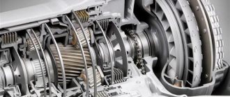
Design and principle of operation
Let's consider the location and design of the KamAZ vehicle gearbox. KamAZ trucks are equipped with manual transmissions. They have 5 speeds. The gearbox is switched by pressing the clutch pedals and moving the gearshift lever to the desired position. Since the car is heavy, it is necessary to transfer the gearbox from one gear to another in several stages.
The principle of operation of the KamAZ gearbox is as follows: with a diesel engine it works either in high mode B or in low mode H. They were created to reduce the load on the engine of a heavy vehicle when it is full, and at the same time not force it to work too actively without load.
The design of a KamAZ gearbox with a divider is simple, but it differs depending on the model of the gearbox. Let's look at the KamAZ gearbox diagram, which is found on diesel vehicles. When driving on a flat road, you need to change gears without a clutch. The design of the KamAZ transfer case can be represented by the following formula: 1B - 2B - 3B - 4H - 4B - 5H - 5B.
Switching speeds is carried out as follows:
- First, switch the gearbox operating mode from high to low using a lever.
- Then release the clutch.
- The lever is set to the desired gear, without jumping over them, but turning everything on in order.
There are gearboxes with automatic mode switching.
How does the divider work on KamAZ?
The gearbox divider or multiplier is an additionally installed overdrive, which converts a 5-speed gearbox into a 10-speed gearbox.
The principle of its operation is as follows. The multiplier reduces the ranges between the main gears, tightening the number of gear ratios of the box and expanding them by 20-25 percent.
This modification allows you to improve such vehicle characteristics as:
- fuel efficiency;
- acceleration speed;
- traction force;
- controllability.
The mechanism is located in front of the gearbox, or slightly to the right of it, since the main unit does not experience heavy loads and does not require structural modifications. This allows you to repair and adjust the divider yourself if a malfunction occurs.
Location and order of gear shifting on KamAZ
Most cars from the Kama plant are equipped with manual gearboxes with 5 steps (with or without a divider). Gear shifting is carried out by moving the gearbox rocker with the clutch pedal pressed. But gears on trucks should not be engaged directly, but in stages. Theoretically, this reduces the load on the engine when driving with a full load, and when working with an empty body, it saves fuel.
The usual operating modes of the KamAZ gearbox are increased “B” or decreased “H”. In cars equipped with a gearbox with a multiplier, switching from mode “B” to mode “H” is carried out by lowering a special single divider lever.
It is important to know how to engage a higher gear when driving a KamAZ with a full load: experienced drivers recommend engaging the first 4 gears in the heavy secondary “H” mode, and then transferring the 4th speed to the “B” mode, switching to the 5th lower gear, and then go to “B”. The shift order may vary depending on the specific gearbox model.
Box KamAZ 15
This transmission is installed on KamAZ-55111, KamAZ-43118 and other models. To accelerate the car to the required speed, the following scheme is used: 1B-2B-3B-4N-4B-5N-5B. This scheme allows the box to operate normally, provided that the rules for operating the mechanism are followed:
- Using a special switch lever, change the operating mode of the box from high to low and vice versa;
- Press the clutch pedal;
- We change gears in order using the rocker.
KamAZ switching diagram:
Specifications
The KamAZ gearbox with a divider includes the following elements:
- a crankcase in which the drive, driven and intermediate shafts assembled with gears are mounted;
- bearings;
- synchronizers,
- reverse gear block,
- top cover of the box,
- gear shift mechanism.
The gearbox of KamAZ vehicles can be five- or ten-speed. The gearbox divider has high and low gears and, in combination with the main gearbox, allows for 10 forward gears and 2 reverse gears. The divider system improves the traction qualities of the machine, makes it easier to control, and reduces the frequency of shifting gears with a lever. Transmission ratios are available in the operating instructions for the device.
The 141 KamAZ gearbox has a reversing light switch. To prevent the simultaneous activation of 2 gears, there is a ball-type lock in the cover, and a spring-finger fuse is used to prevent accidental engagement of reverse gear. The gearbox with divider weighs 320 kg. The cuffs are located in the shaft covers. They protect the gearbox from clogging and prevent oil leakage. Insufficient oil volume in the gearbox leads to its damage. When you first fill the gearbox there should be 9 liters of oil, when changing the fluid - 8 liters.
Technical characteristics of the KamAZ-141 gearbox: Carter:
- The diameter of the bearing bore is 150 mm.
- The diameter of the hole in the gear block axis is 32 mm.
Main shaft:
- The diameter of the front bearing journal is 24 mm.
- Rear bearing - 59 mm.
The secondary shaft has the following diameters for the parts:
- Fourth gear gear bushings - 63 mm.
- Roller bearings - 80 mm.
- Reverse gear bushings - 70 mm.
- The outer diameter of the sleeve is 72 mm.
Intermediate shaft:
- The diameter of the front bearing journal is 65 mm, the rear one is 49 mm.
- The diameter of the rear bearing cup is 119 mm.
- The diameter of the intermediate shaft is 65 mm.
- The inner diameter of the gear is 65 mm.
The weight of the gearbox with divider is 320 kg.
Transmission
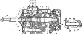
Rice. 128. Gearbox model 14: 1 - drive shaft; 2 — cover of the rear bearing of the drive shaft; 3, 23 — adjusting gaskets; 4 — lever rod; 5 — protective ring; 6 — lever support cover; 7 — lever support block; 8 — sealing ring; 9 — rod support; 10 - spring; 11 — gear shift lever support; 12 — axis of the reverse gear block: 13, 31—thrust washers; 14 — reverse gear block; 15 — roller bearing: 16 — bolt with pin; 17 — lock washer; 18 — top cover; 19, 32, 36 — sealing gaskets; 20 — cover of the rear bearing of the driven shaft; 21 — retaining ring; 22 — ball bearing of the rear driven shaft: 24 — speedometer drive worm; 25, 39 — sealing cuffs; 26 — flange mounting nut; 27 — driveshaft mounting flange; 28 — cup of the rear bearing of the intermediate shaft; 29 — bearing cover; 30 — spherical roller bearing: 33 — intermediate shaft; 34- gearbox housing; 35- driven shaft; 37 — cover of the front bearing of the intermediate shaft; 38 — clutch housing; 40 — clutch release fork; 41-shaft of the clutch release fork; 42 — clutch release
The model 14 gearbox (Fig. 128) consists of the following main components: gearbox housing 34, in which drive 1, driven 35 and intermediate 33 shafts assembled with gears, synchronizers and bearings are mounted; gear block 14 reverse; top cover 18 of the box with gear shift mechanism assembly. A clutch housing 38 is attached to the front end of the gearbox housing.
The shaft bearings are closed with covers with sealing gaskets. Cover 2 of the rear bearing of the drive shaft is centered with an internal bore along the outer race of the bearing; The surface of the cover, machined along the outer diameter, is the centering surface for the clutch housing. Two self-clamping cuffs 39 are inserted into the inner cavity of the lid. The working edges of the cuffs have a right-hand notch. The internal cavity of a larger diameter is designed to accommodate an oil injection device; Spiral blades at the end of the cover prevent the oil from spinning in the injection cavity by the oil-discharge ring, thereby reducing centrifugal forces, and therefore contribute to an increase in excess oil pressure in the injection cavity. In the upper part of the cover there is a hole for supplying lubricant from the gearbox oil accumulator to the discharge cavity. The rear driven shaft bearing cover 20 is attached to the rear end of the transmission housing and is centered on the outer race of the rear driven shaft bearing 22. At the back of the cover there is a cuff 25 with a boot, on the working edge of which there is a left notch. At the bottom of the cover, in a special bore, there is a roller made integral with gear 10 (Fig. 129) of the worm pair of the speedometer drive. At the protruding end of the roller, which has a flat, the drive gear 12 of the cylindrical pair of replaceable speedometer drive gears is installed. The driven spur gear 13 is installed on the speedometer drive shaft 14, which rotates in the bore of the speedometer drive sensor flange 16. The cavity of the replacement gears is isolated from the oil bath of the gearbox, and the gears are lubricated with CIATIM-201 grease, which is added during assembly. The lubricant is kept from leaking out by the oil-draining thread made on the roller and by the cuff. To ensure correct speedometer readings, the number of teeth of replaceable spur gears is selected depending on the final drive gear ratio (Table 21).
In the bosses of the right wall of the gearbox housing there is a boring into which axis 12 (see Fig. 128) of the reverse gear block is pressed. To prevent it from falling out, the axle is secured with a lock washer 17, screwed with a bolt 16, which has a drilling into which a plastic pin is inserted. The pin seals the threaded connection and prevents lubricant from leaking out.
Oil is poured into the gearbox through the neck located on the right wall of the crankcase. The neck is closed with a plug with a built-in oil dipstick. In the lower part of the crankcase, drain plugs 8 and 9 are screwed into the bosses (see Fig. 129); a magnet is mounted into plug 8, which catches metal particles that may be in the oil. On both sides of the crankcase there are hatches for installing power take-off boxes, which are closed with covers 5 with sealing gaskets 6. The hatches are made in accordance with GOST 12323-66. Allowable power output is 22064.97 W (30 hp) from each hatch. Power take-off while the vehicle is moving is not allowed.
In the internal cavity of the crankcase, in the front part of the left wall, an oil accumulator is cast, into which, when the gears rotate, oil is thrown and, through a drilling in the front wall of the crankcase, enters the cavity of the rear cover of the drive shaft and onto the oil injection ring.
There is an oil pocket in the upper right part of the rear wall, into which oil is thrown by the rotation of the gears. From the oil pocket, oil flows through a drill in the crankcase wall into the cavity of the rear cover of the driven shaft to lubricate the worm pair of the speedometer drive. The gearbox gears are arranged in pairs with mating gears according to the contact patch and noise level.
Table21
| Number of replaceable cylinder teeth | Final drive ratio | |||
| ical gears | 6,53 | 7,22 | 5,94 | 5,4 |
| Master Slave | 24 24 | 23 26 | 25 23 | 26 23 |
Rice. 129. Gearbox model 14. Rear view: 1 — gear lever; 2 — sealing pin; 3 - setscrew; 4 — clutch fork shaft lever; 5 — power take-off hatch cover; 6 - sealing gasket; 7 — plug with oil level indicator; 8 — drain plug with a magnet; 9 — drain plug; 10 — speedometer drive gear; 11 — gear bushing; 12 — drive gear of the speedometer sensor; 13 — driven gear of the speedometer sensor drive; 14 — speedometer drive shaft; 15 — sealing cuff; 16 — speedometer sensor flange
| Rice. 130. Drive shaft assembly: 1 - drive shaft; 2 - ball bearing; 3 — bearing retaining ring; 4 — ring nut; 5 — oil injection ring; 6 — locking ball |
Rice. 132 .
Driven shaft assembly: 1 — retaining ring; 2 — front roller bearing; 3 — synchronizer of IV and V gears; 4 — thrust ring; 5-rollers bearing 4th gear; 6 — 4th gear gear bushing; 7 — gear III gear; 8 — roller bearing; 9 — synchronizer for 2nd and 3rd gears; 10 - 2nd gear gear; 11 — reverse gear: 12 — clutch for engaging 1st gear and reverse gear; 13 — bushing of the 1st gear gear; 14 - 1st gear gear; 15 — thrust washer; 16 — driven shaft; 17 — reverse gear bushing; 18 — 4th gear gear; 19 - spring: 20 - intermediate bushing; 21 — locking key The drive shaft of the gearbox (Fig. 130) is made integral with the gear; its front support is a ball bearing located in the crankshaft bore. The bearing cavity is filled with grease 158 and sealed with a collar. A ball bearing 2 and an oil injection ring 5 are mounted on the rear end of the shaft with a stop at the end of the gear, which is locked from turning on the shaft by a ball 6. Parts 2 and 5 are tightened with a ring nut 4, which is locked by opening the belt into the grooves of the shaft.
The oil injection ring on the outer surface has a right-hand, three-start screw thread, which pumps oil into the injection cavity.
The axial stroke of the drive shaft is regulated by a set of steel spacers 3 (see Fig. 128) with a thickness of 0.2 and 0.3 mm, installed between the end of the drive shaft cover and the outer race of the bearing.
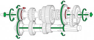
Intermediate shaft 1 (Fig. 131) is made integral with the rims of the gears of the first, second and reverse gears. At the front end of the shaft, gears 7 and 6 of the third and fourth gears and gear 3 of the intermediate shaft drive are pressed and secured with segment keys 8.
Driven shaft 16 (Fig. 132) assembled with gears and synchronizers is installed coaxially with the drive shaft. At the front end of the shaft there is bearing 2 with an attached inner ring; all gears of the shaft are mounted on roller bearings, of which the fourth gear gear bearing is bulk, without a cage. Gears 18 and 7 of the fourth and third gears are secured in the axial direction by a thrust ring 4 with internal splines, which is installed in the shaft recess in such a way that its splines are located opposite the shaft splines, and is locked from rotation by a spring-loaded locking key 21. A channel is drilled along the axis of the shaft for supplying lubricant through radial holes to gear bearings. Oil is supplied to the channel by an oil injection device located on the drive shaft.
For shockless shifting of the second, third, fourth and fifth gears there are two finger synchronizers 3 and 9 of the inertial type.
Rice. 134. Lock and latches of the switching mechanism: 1 - lock ball; 2 — glass of locking ball; 3 — locking ball spring; 4 — lock pin; 5 - locking ball
| Rice. 135. Gear shift fuse: |
1
— fuse spring; 2 - fuse; 3 fuse pusher
Rice. 136. Ten-speed gearbox model 15: 1 - main five-speed gearbox; 2 — spacer sleeve; 3 — sealing gasket; 4 — gear divider; 5 — front roller bearing of the drive shaft; 6 — drive shaft; 7 - ring nut; 8 — washer; 9 — synchronizer clutch; 10 — adjusting gaskets; 11 - cover of the rear bearing of the drive shaft
The gear shift mechanism (Fig. 133) is mounted in the top cover 2 of the gearbox and consists of three rods, three shift forks 3, 6, 7, two rod heads, three clamps (Fig. 134), fuse 2 (Fig. 135) first gear and reverse gear as well as the rod lock. The rod lock consists of two pairs of balls 1 (see Fig. 134) and a pin. 4. The balls are located between the rods in the bushings, the pin is located in the hole in the middle rod between the balls. The diameters of the balls and the distances between the rods are chosen in such a way that when any rod moves from the middle position, the balls come out of the holes of the moving rod and enter the holes of the stationary rods, blocking them with the body. On top of the cover of the switching mechanism there is a lever support 11 (see Fig. 128) with a rod 4 moving in a spherical support. On the right side of the support there is a set screw 3 (see Fig. 129), which fixes the lever in the neutral position. In the working position, the screw must be turned out.
The ten-speed gearbox of model 15 (Fig. 136) consists of the main five-speed gearbox 1 and the front two-stage gearbox of the 4th gear divider.
The main five-speed gearbox of the Model 15 is maximally unified with the gearbox of the Model 14, except for a small number of parts, the design of which is changed due to the use of a gear divider. Design changes to the main gearbox are listed below:
— the design of the drive shaft 6 and the rear bearing cover 11 has been changed; There is no sealing gasket between the cover and the gearbox housing;
— the front support of the drive shaft is a roller bearing 5 located in the bore of the divider drive shaft;
— instead of an oil injection ring on the shaft, synchronizer coupling 9 is secured with a nut on the splines;
— the front cover of the intermediate shaft is missing; instead, the axial displacement of the front bearing of the intermediate shaft is limited by spacer sleeve 2, which is also an oil slinger;
— the oil baths of the gearbox and the divider are connected to each other by two holes located in the lower part of the front end of the gearbox and in the rear wall of the divider.
The axial stroke of the drive shaft is regulated by steel spacers 10 with a thickness of 0.2 and 0.3 mm.
The gear divider (Fig. 137) is mechanical, the gearbox consists of one pair of cylindrical gears, 2 drive and 11 intermediate shafts, 7 synchronizer and gear shift mechanism. The gear shift mechanism is controlled pneumatically.
Rice. 137. Gear divider: 1 — adjusting shims; 2 — drive shaft; 3 — oil injection ring; 4 - ball bearing; 5 — rear cover of the drive shaft bearing; 6 — hatch cover; 7 — divider synchronizer assembly; 8 — drive shaft gear; 9 — drive shaft gear bearings; 10 — rear roller bearing; 11 — intermediate shaft
The axial stroke of the drive shaft is regulated by a set of metal spacers 1 with a thickness of 0.2 and 0.3 mm, installed between the rear cover 5 and the outer race of the ball bearing. At the front end of the shaft, involute splines are divided into three crowns by two grooves. The teeth of the outer rings are thinner than the teeth of the middle ring to create a “lock” that prevents the gears in the divider from switching off on their own. An inertial type finger synchronizer 7 is movably mounted on the splines.
The drive gear 8 rotates on two roller bearings 9. The oil injection ring 3 supplies oil through the inclined drillings of the drive shaft into its internal cavity, from where it enters the channels of the drive and driven shafts of the main gearbox.
Intermediate shaft 11 of the divider with a pressed-on drive gear of the intermediate shaft rotates on two bearings: front 12 and rear 10.
The gear divider shift mechanism is mounted on the divider housing on the left.
The remote drive for controlling the main gearbox (Fig. 138) consists of a swing lever 4 for gear shifting, support 2 for the gear shift lever mounted on the front end of the engine cylinder block, front 10 and intermediate 17 control rods, which move in spherical bushings 13 made of metal-ceramic, the bushings are sealed with rubber rings 12 and pressed by a spring 14 to the crayon 11. The spherical supports of the front link are located in the bore of the support bracket 2 and in the flywheel housing. The intermediate link support is installed on the clutch housing. An adjusting flange 18 is screwed onto the rear end of the intermediate rod and secured with two coupling bolts 24.
The gear shift lever support (Fig. 139) consists of bracket 1, corrugated hatch seal 5, seal spring 6, shortened gear shift lever 4, which with its spherical part rests on a polyurethane bushing 7, which dampens vibration of the lever. The sphere is pressed from above through support washer 2 by a spring. Set screw 8 secures the shift lever in the neutral position when adjusting the drive. In the working position, the bolt must be unscrewed and secured with a locknut.
The remote drive for controlling the main gearbox of model 15 differs from the drive of the gearbox of model 14 by an extended intermediate rod and a gear shift handle in which switch 3 (see Fig. 138) of the divider control valve is mounted.
The pneumatic gear shift system of the divider (Fig. 140) consists of the following main assembly units: pressure reducing valve 4, control valve 3, gear shift mechanism 5 of the divider with air distributor 6, valve 1 for switching on the gear divider, valve stop 2 and air ducts.
Air from the receiver of the IV circuit of the drive of the auxiliary brake system at a pressure of 608...736 kPa (6.2...7.5 kgf/cm2) is supplied to the input of the pressure reducing valve 4, at the outlet of the valve a constant pressure is maintained equal to 387...436 kPa (3, 95…4.45 kgf/cm2), the value of which is regulated by spacers installed on the spring housing.
Divider control valve 3 (see Fig. 140), depending on the position of the spool, directs the air coming from the pressure reducing valve into one of the cavities under the pistons of the air distributor 6 and moves the air distributor spool to one of two extreme positions, thus preparing supplying air to cavity A or C of the power cylinder.
Preliminary gear selection in the divider is made by moving the valve switch lever to position B or H, which moves the valve spool through a braided cable.
The air supply from the pressure reducing valve under the piston of the power cylinder is carried out by the valve (Fig. 141) for switching on the gear divider, the opening of which is carried out by stop 2 (see Fig. 140) attached to the piston pusher of the pneumatic-hydraulic clutch release booster. The valve opens at the end of the pusher stroke, that is, when the clutch is completely disengaged.
How to change gears on KamAZ
To change gears correctly, you need to know how the transmission works. The gearbox is designed in such a way that movement is often carried out at a reduced speed, so the machine can transport heavy loads. KamAZ has a 5-speed gearbox. You need to change gears using the clutch pedal and lever.
Start of movement
Before you start moving, you must press the reduced speed. Shift gears only with the clutch pedal depressed. The gear shift pattern is based on staged gear shifting. To start driving a truck, you need to spin the crankshaft of the internal combustion engine.
The second gear must be engaged when the needle on the tachometer reaches mark 3, which means 3000 rpm. This method of gear shifting will make it possible to extend the life of the gearbox and reduce gasoline consumption.
Switching speeds
Let's consider the procedure for switching gears after the car has already started moving. When KamAZ accelerates, the gear shift order is: 4H - 4B - 5H. To engage speed 2, the crankshaft speed must increase to 3000 rpm according to the tachometer readings. The functions of the crankshaft are basic.
Reverse
To engage reverse on a truck, you need to place the switch in the lower left position. Reverse gear cannot be engaged while the vehicle is moving. To engage reverse, you must first completely stop the unit, then perform a maneuver.
Start
To know how to properly drive a KamAZ dump truck, you need to understand the gear shift pattern. As in the standard version, manipulations take place using the clutch pedal.
Switching stages:
- 1st gear, high mode (B);
- 2nd gear, high mode (B);
- 3rd gear, high mode (B);
- Transition to the 2nd low (H) stage and switch to 4th gear;
- Transition to the primary stage (B), the gear remains in 4th;
- Shift to a lower gear (H), engage 5th gear;
- Return to the higher gear (B), stay in 5th gear.
KamAZ:
The main feature of starting to move on a KamAZ is a smooth start and acceleration using lower gears. In the case when the dump truck is heavily loaded, or the traffic is in difficult conditions, it is advisable to switch the first 4 gears in low mode (H), then switch to 4th high gear, then lower 5th gear (H) and then to 5th -th increased (B). Manipulations are carried out when the required crankshaft speed is reached. Directly at the start in 1st gear, the shaft speed reaches 7000 min-1, the transition to 2nd gear is made when the speed reaches 3000 min-1. The correctly selected mode saves fuel and minimally wears out the power plant.
Switching rules under different conditions
Gear changes depend on the various conditions in which the vehicle is moving. These rules should be followed so that during the use of the gearbox it does not fail.
Climb
During an ascent, you must switch the gearbox to mode H, as a result of which the transmission will begin to operate at increased voltage.
The following rules must be followed:
- When switching from 1st to 2nd gear when ascending a KamAZ truck, you must use the method of depressing the clutch pedal twice.
- In order for the crankshaft to work correctly when changing gears, you need to use the fuel pedal; it also needs to be pressed periodically. At the same time, you can overcome any steepest climb.
- The shaft speed when lifting must be more than 2000 rpm. Otherwise, the engine may shut down, which may cause an accident while driving on the road.
- During the climb, switch to the desired mode, this will facilitate the operation of the engine and all components of the machine.
Descent
Some drivers turn off the engine when descending a mountain to save gas. This should not be allowed at KamAZ.
If you turn off the internal combustion engine during a trip, the electric booster will not perform its functions, which will lead to the steering wheel locking.
KamAZ braking occurs not only as a result of stopping the engine, but also by activating the auxiliary braking system. When a heavy vehicle is going downhill and the driver applies the auxiliary brakes, the clutch should not be depressed and the driver should not shift from one gear to another.
Icy areas
You need to drive a truck on icy areas with maximum speed and range. When braking, you must use the engine stop assist system. If emergency braking is required, the operator must stop the trailer wheels. If you do not take this rule into account, you may end up in a skid.
It is possible to slow down the internal combustion engine only as an exception, as this can lead to its wear. When braking, the wheels should not slip. To avoid this, you need to turn off the reduced speed, which will help reduce the rotation of the crankshaft.
Skid
When skidding, do not disengage the clutch. When the truck skids, you need to turn the steering wheel in the direction of the skid. If the KamAZ skids, you need to take your foot off the gas pedal and press the differential. This must be done using the regulator located on the panel. As a result, the indicator on the panel will turn on. You need to start the move from the second high gear. After overcoming the skid, the differential should be unlocked.
Hill climb control
Driving up a slope is accompanied by the gearbox switching to a lower mode (H). This makes the transmission work harder and overcome obstacles more easily.
- When lifting heavy equipment, shifting from first to second gear is carried out using the double clutch method;
- To ensure the operation of the power plant, depress the gas pedal to prevent an interruption in the fuel supply;
- The crankshaft speed readings do not fall below 2000 min-1, otherwise the power plant will overheat and stop working.
Switching features in different models
On KamAZ vehicles of various models and configurations (tractor tractors - 44108 or 5490; dump trucks - 6520 or 55111; trucks - 5320, or military model 5350; road trains - 5410, 65206) the following gearboxes are installed:
- 141, 142 and 144 – mechanical gearboxes, 5-speed (used in light trucks, and are similar in design and operating principle to passenger car gearboxes);
- 152 and 154 – mechanical gearboxes with a multiplier, ten-speed;
- German-made ZF-6S1000 gearbox with mechanical shifting, 6-speed with a full set of synchronizers;
- ZF-9S109 and ZF-9S1310 – mechanical 9-speed gearboxes with a range shifter.
Models of gearboxes for trucks differ from each other in the number of stages, the complexity of the device, the design of the rocker and the order of gear shifting. We will give a more detailed description of various gearboxes using the example of several KamAZ models.
Operating manual in PDF »
Design and switching diagram of the KamAZ-5320 gearbox with a divider
The KamAZ-5320 is equipped with two models of gearboxes - a five-speed 142 or a ten-speed 152 with a divider. Switching gears on KAMAZ-152 occurs according to the following scheme:
Specifications:
- number of steps – 10;
- box control type – mechanical;
- divider control type – pneumomechanical preselector;
- bearings – roller bearings with and without a cage (gearbox gears), ball and spherical roller bearings (gearbox shafts);
- synchronizers – finger-type inertial;
- gearbox – front two-stage.
KamAZ-4310: switching diagram
Military trucks of the 4310 model have increased cross-country ability and are equipped with a five-speed three-way gearbox 14 (it differs from the 141 in that it has a direct fifth gear, while the 141 model has a direct fourth gear, the fifth gear here is an accelerating one). The gear shift mechanism is similar to that discussed above for the main gearbox of the KamAZ-5320 vehicle with a divider. The diagram is shown in the photo:
Gearbox KamAZ-43118
KamAZ-43118 is equipped with a KAMAZ-154 model gearbox with a divider, which has a gear shift circuit similar to the 152nd model.
Gearbox ratios:
Gearbox KamAZ-65115
Depending on the modification, the model 65115 dump truck is equipped with a reinforced gearbox with a KAMAZ-154 multiplier, or a German-made nine-speed gearbox – ZF9.
The gearbox with a mechanical control type has gear ratios in the range of 9.48 - 0.75; and 8.97 for reverse gear. Maximum torque – 1300 Nm. The gear shift diagram is shown below:
Types of boxes used
During the production of cars, the KamAZ gearbox device was repeatedly refined and improved. The process was influenced by the operating conditions of the equipment and the weight characteristics of the machine. The more difficult the operating conditions of the vehicle, the more stringent the requirements for the transmission. As a result, boxes with different designs are often installed on the same KamAZ chassis.
Modifications of installed boxes:
- Box "14";
- Box "15";
- Box "142";
- Box "152";
- Box "16";
- Box "154";
- Box ZF-9;
- Box ZF-16;
Box KamAZ-142:
Modification “14” is a five-speed mechanism with a gearbox. The fifteenth model is equipped with ten stages; the design includes a two-stage divider located at the front. The mechanisms are among the first gearboxes produced for the needs of KamAZ. The devices are controlled remotely using a lever. The mechanical gearbox receives commands from pneumatic and mechanical devices through a selector.
Box “142” (Article 142.1700025), this is an improved model of the fourteenth transmission. The product is equipped with five forward and two reverse speeds.
“152” model (Article 152.1700156), this is the improved fifteenth transmission. The box makes ten forward and two rear shifts. In addition, the design is equipped with a divider to prevent power loss in difficult areas.
It is characteristic that models “fourteen” and “fifteen” are completely interchangeable with modified transmissions “142” and “152”.
Malfunctions and repairs
Transmission repair consists of disassembling the unit, diagnosing, repairing or replacing worn elements. After the mechanism is restored, the unit is reassembled and the system is tested in operation. You can contact a service center, but it is better to repair the transfer case yourself.
How to check the oil level
The oil level in the box is checked as follows. Unscrew the crankcase plug. When checking, you must install the crankcase indicator into the hole until it stops. The oil from the crankcase of a ten-speed manual transmission is drained through 3 holes. Of these, 2 holes are located in the lower part of the gearbox housing, and the third is located in the divider. The five-speed gearbox housing is drained through 2 holes.
Change of oil
To change the oil, you need to wash the gearbox housing with engine oil. Clean the magnetic plugs from metal particles and fill in oil to the top line of the indicator. The oil level is measured after 5 minutes. When the car is moving, the gearbox should operate without hesitation, speeds should be switched freely and locked firmly. Loud noise may indicate worn shaft bearings, insufficient oil level, or poor quality lubricant in the crankcase.
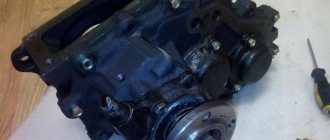
How to remove the box
Removing the gearbox is carried out as follows:
- You need to remove the driveshaft. To do this, unscrew the 4 fastening nuts.
- The PSU is being removed.
- Dismantle the starter mountings.
- Disconnect the tube that goes to the reduction gear.
- Remove the gear shift lever.
- Place a jack between the flywheel and the engine pan, and dismantle the engine through a wooden stand.
- Unscrew the rear yoke nuts and remove it.
- Dismantle the spacer rod.
- Unscrew the exhaust system bracket fastening bolts.
- Connect the hoist to the bolts and tighten it.
- Unscrew the fastening nuts to the side engine mounts.
- Unscrew the bolts that secure the gearbox to the internal combustion engine.
- Raise the hoist and move the gearbox away from the engine to the output of the transmission input shaft.
- Pull out the gearbox.
How to adjust
Now you need to adjust the gearbox and troubleshoot components and parts. If they fail, replace them with new ones. Spline connections must not have defects or chips. Gear bearings should be replaced after first inspecting the place where they are installed to see if there is any wear or areas pressed through by the rollers.
The shaft bearings are replaced because, as a result of breakage and metal shavings getting into the oil, the rolling areas of the bearings were damaged, which could cause gearbox failure. Inspect the gears, detect damage and wear of gear teeth. The conical synchronizer races must not be deformed or worn. The guide shafts should not be loose. There should be no damage to the splines.
How to assemble correctly
The gearbox is assembled in the reverse order. The intermediate shaft is installed in the gearbox housing. Mount the bearings - front roller and rear spherical. Tighten the support washer. Fix it with a nut and close the rear cover of the spherical bearing mount. Install gaskets. The shaft should rotate easily, there should be no jamming of the part when moving.
Repair diagram for KamAZ-5320 gearbox with divider
To repair the KAMAZ-152 gearbox with a divider, it must be disassembled. Analysis includes the following steps:
- To disassemble the box, you will first need to dismantle the air switch and unscrew the fasteners;
- remove the gearbox shift shaft and fork;
- the next step will be to dismantle the fork and release shaft, as well as the synchronizer;
- Next, you need to open the rear bearing cover by unscrewing the screws that first fix it;
- dismantle the bearing and shaft;
- also, to open access to the gearbox multiplier, you will need to remove the support roller washer, metal cup and driven shaft bearing;
- using a rubber (not metal) hammer or a wooden block, you must carefully remove the bearing from the multiplier housing, being careful not to crush the part;
- next you need to remove the coupling and oil injection nuts using the appropriate wrenches;
- The last stage of disassembling the unit is to dismantle the roller bearing, bushing, and gearbox drive gear.
Next, you should inspect all the parts and replace worn ones, and then assemble the device, following the above instructions in reverse order.
Possible Kamaz gearbox malfunctions and ways to eliminate them
Mechanism wear is the most common malfunction in the Kamaz vehicle’s gearbox. As a rule, bearings and gears suffer more often, since they are constantly under load, in motion and rubbing. Repair in this case involves replacing these parts.
Using box 152 as an example, let’s look at how the problematic box behaves:
- noise and knocking increase;
- gears fly out spontaneously;
- the mechanism is difficult to turn on;
- speed is locked in one position.
Repair always involves dismantling and disassembling the unit with subsequent identification of defects. Problematic and worn elements are changed, parameters are adjusted. The oil must be renewed. Then, after assembling and installing the gearbox in place, a verification test drive is carried out.
There was a noise
As a rule, when the clutch is released, the noise disappears. This usually happens when the main shaft bearing is worn out. The gearbox makes noise in almost all gears, less often in fifth. Over time, the noise gets worse.
The cause of the howling can be not only the gearbox, but also the clutch. Therefore, after removing the box, before disassembling it, it is advisable to check the device. We need to start the engine. If you hear a metallic clanging sound, it is either the basket disk springs are worn out or another clutch malfunction.
Rear and first do not turn on
Difficult engagement of reverse and first gear may indicate clutch slip. In other words, the disc wears out and the adjustment and functioning of the drive deteriorates. As for the problems in the box itself, wear of the synchronizers is possible - for forward gear. Another reason is the lack of oil in the box.
If it is difficult to change gear when the car is stationary and the engine is turned off, the fault is clearly in the gear selection mechanism of the transmission. It is either broken or out of adjustment.
Gears turn off (fly out)
This malfunction is related to the gear shift mechanism. It is possible that the fork liners are worn out or their clamps are loose. This often happens when driving uphill for a long time. The car, as a rule, must be loaded, and it is necessary to engage in lower gears - first or second. The reason is most likely due to worn synchronizers. It is possible that the rims are worn out on the teeth, which is why the speed is knocked out.
Change the transmission oil in a timely manner, periodically monitor the operation of the clutch, and load the car less! Then Kamaz will not be afraid of any roads.