What is the difference between the KamAZ gearbox and what is the principle of its operation?
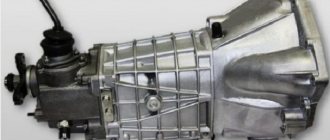
Almost all KamAZ trucks that are found on our roads are equipped with manual transmissions, which, in turn, have only 5 speed levels.
In this case, gear shifting is carried out in the usual way - by pressing the clutch pedal and moving the gearbox lever to the required position. But there is also a nuance here: since KamAZ is a heavy-duty vehicle, it is necessary to move the gearbox lever from one gear to another in stages. The usual mode of operation of a KamAZ gearbox with a diesel engine is either an increased “B” mode or a decreased “H” mode (the designers created them specifically to reduce the load on the engine of a heavy-duty vehicle when it is fully loaded, but at the same time not to force it to be overly active work when driving with an empty trailer).
SUVs with reduction gear and differential lock
Currently, there are still real off-road conquerors, equipped with all the necessary equipment in order to feel as comfortable as possible on any surface. Among such cars are, for example, Chevrolet Trailblazer, Hummer H3, Land Rover Discovery.
The Trailblazer has a large body, a frame structure and just a huge list of technical advantages. He has a bright and brutal appearance. In 2015, the model received quite significant updates both in the exterior and in the technical “stuffing”. The suspension is soft, but this fact introduces some drawback to the handling of the SUV: a slight roll appears during sharp turns. The car pleases with the quality of the ride, which it can provide if it has a full set of necessary systems.
Now let's move on to the American model of a real off-road conqueror - the Hummer. The production of this car was based largely on military technologies. It is not surprising that he was able to create a truly brutal SUV. Its serial production stopped back in 2010, and last year it was announced that the Hummer H3 can only be purchased by special order. The car has huge ground clearance, large engines, excellent wheels shod with off-road tires, and, importantly, it is equipped with one of the best low-range gearing and differential locking systems, which are borrowed from the military industry.
Discovery remains one of the few British SUVs to retain its body-on-frame design. It is distinguished not only by its excellent appearance, but also by increased comfort and cross-country ability. The range of engines, although not very rich in choice, looks impressive. Locking is available on it in several modes, and the car also boasts good all-wheel drive. The reliability and quality of the car are truly impressive.
Overdrive device
Volkswagen Passat Das graue Auto Logbook Replacing the gear shift cable
The overdrive gear used in divider-type gearboxes allows you to select gentle driving modes and is used mainly for long trips at high speeds (in relation to trucks, of course). In addition to saving fuel, which in such cases can be significant, the use of a divider makes it possible to reduce the noise level during operation of the engine-transmission combination, reducing the load and wear of the power unit.
When the divider is turned on, the propeller shaft begins to rotate at a higher speed than the engine crankshaft. The divider doubles the number of gears on the vehicle, both forward and reverse. But if the machine has other gearboxes (for example, reduction gearboxes), their simultaneous use will be impossible.
Design and operation of a gearbox with a divider
CVT gearbox variator
The purpose of the gearbox is to change the speed of movement, provide reverse movement, and long-term disconnection of the transmission from the engine. To ensure the most efficient operation of the engine in a certain range of crankshaft frequencies and to obtain the necessary driving torque on the wheels when the load changes, a gearbox with variable gear ratios is introduced into the transmission.
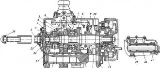
Three-shaft four-speed gearbox. The input shaft receives rotation from the engine shaft. The front end of the secondary shaft is mounted on a bearing at the end of the primary shaft. Constant mesh gears are mounted on the intermediate shaft: the front gear is in mesh with the input shaft gear, the other three are in constant mesh with gears mounted on roller bearings on the secondary shaft. Spur gears are manufactured together with the wheels. Toothed hubs are secured to the secondary shaft by means of keys, on which sliding gear couplings are installed.
A splitter is an additional gearbox in which the power flow is divided into two or three branches. It has more gears, which are smaller in size, and therefore have lower moments of inertia and peripheral speeds. The use of such schemes is explained by the desire to increase the service life of the transmission with high transmitted power. Multi-stage transmissions are created on the basis of the main four-, five- or six-speed basic coaxial three-shaft box, attaching an additional box to it. It usually has two gears (direct and reduction) and provides double the number of gears. The use of a three-speed additional gearbox allows you to triple the number of gears in the base box. In both cases, the driver uses two controls: one basic, the other an additional box. If the low-range gear ratio in the secondary box is large enough to at least double the overall range, it is called a "deep multiplier". If it almost does not increase the overall range, but serves to obtain “halves” between the gears of the main box, it is called a “divider,” meaning that it divides the available range into a larger number of steps. Today, two additional ones are often docked to the base box - both in front and behind. Naturally, one of them is a demultiplier, the other is a divider.
The divider has a simple design and a minimum number of gears. The efficiency of a box with a divider is practically no different from the efficiency of the base box, since the number of gears transmitting the power flow is maintained. When installed at the front, the disadvantage of the divider is that it increases the torque at the input of the base box, which forces the use of a more powerful and, accordingly, heavier unit. This problem can be solved by installing a divider at the rear, but this usually leaves room for a range multiplier, the installation of which at the front is practically impossible due to the large low gear ratio.
TELL WHERE AND WHERE THE DIVIDER IS CONNECTED, HOW IT WORKS, PROVIDE KINEMATIC DIAGRAM
Motor vehicles
MAZ - gearbox: device, characteristics, principle of operation
The lower edge of the shift lever is connected to the same unit. The method of fastening is similar to the above method. Part of the lever extends through the cabin floor, ensuring the integrity of all other connections. This design makes it possible to tilt the cabin without the need to separate and deform existing elements and assemblies.
We recommend reading: Mortgage through a rural house Orenburg
The box is located in a MAZ car between the crankshaft and the driveshaft. The first comes directly from the engine. The second is directly connected to the wheels and drives them. List of works that lead to speed adjustment:
Divider - transfer
Automatic transmission
The gear divider is designed
| Ten-speed gearbox. |
The gear divider is mechanical, accelerating with a pneumatic drive for engaging low and high gears. The divider consists of a housing / 7, cast integrally with the clutch housing, a primary 19 and intermediate / / shafts, one pair of gears, a synchronizer and a gear shift mechanism.
The gear divider (Fig. 16.1.) is an additional gearbox in design, the housing 7 of which is rigidly docked to the gearbox housing. The divider housing houses the drive 2 and intermediate 6 shafts, a pair of gears 3 and /, a synchronizer 5 and a switching mechanism. The intermediate shaft of the divider is permanently splined to the intermediate shaft of the gearbox.
In a scheme with a gear divider, a gearbox in the form of an additional pair of gears is installed in front of the main gearbox, as a result of which the number of gears doubles while ensuring high efficiency, since the number of meshing pairs remains minimal (equal to two), and ease of control of the additional constant pair of gears is ensured.
| Timing diagram of the transmission divider operation. |
The timing diagram of the transmission divider block is shown in Fig.
Air leakage from the air ducts of the gear divider control pneumatic system is determined by ear when the control switch is alternately moved to the high gear and low gear positions. The air line of the divider switching system is checked with the clutch pedal pressed all the way.
At the bottom right, under the lever of the release fork shaft, there is a gear divider activation valve.
Some cars (a number of models from the Kama Automobile Plant) use a gear divider installed as an attachment to the main gearbox.
Multi-stage gearboxes according to the kinematic scheme come in the following variants: with a gear divider and with an additional gearbox.
| Lubrication points for the clutch and gearbox with divider for KamAZ vehicles. |
Install the pneumatic booster in the following sequence: secure the booster to the clutch housing (divider) with two bolts and spring washers; connect hydraulic line 10 of the pneumatic booster and pneumatic line 15; install the release spring 8 of the clutch release fork shaft; pour brake fluid into the compensation cavity of the master cylinder through the upper hole with the protective cover removed; pump the hydraulic drive system; check the tightness of pipeline connections; eliminate leakage of brake fluid by tightening or replacing individual parts; check and, if necessary, adjust the gap between the end of the cover and the travel limiter of the gear divider engagement rod.
Repair of gearbox divider for KAMAZ vehicles
The list of repair work for the gearbox divider consists of disassembling the structure of the device, then there is the process of troubleshooting and replacement of worn elements, then the process of assembly and testing.
Disassembly of the divider structure is carried out according to the following algorithm:
- First, the gear shift fork is dismantled; to do this, you need to remove the air switch, unscrew and unlock the fastening bolts and remove the roller;
- the synchronizer is dismantled;
- a one-time removal of the shaft and fork located on the release lever is performed;
- the fasteners that hold the rear bearing cover on the input shaft are unscrewed. Next, this cover must be removed;
- together with the bearing, the shaft itself must be dismantled; in this case, the teeth of the second shaft must be aligned with the cutout located on the drive gear;
- thanks to the presence of threaded holes, which are specially made on the intermediate shaft for easy removal, the bearing cover is dismantled;
- Next, you need to unscrew and unlock several fasteners to remove the support bearing washer, and also dismantle the roller bearing on the driven shaft. To directly remove the bearing, you will have to remove the cup where it is located. To do this, simply unscrew the fastening bolts;
- The bearing is removed together with the glass;
- then you need to knock out the shaft and remove the bearing from the divider housing. For these purposes it is better to use a wooden beam. Under no circumstances should the shaft be knocked out with a hammer. This may damage the parts;
- All that remains is to disassemble the input shaft. To solve this problem, you will need a vice, since the design provides a coupling nut with a thread on the left side. The splined part of the shaft is clamped in a vice, after which you can remove the oil pressure washer, as well as the roller bearing and bushing and the drive gear.
The divider is assembled in the reverse order.
The last, but not least, stage of repair is to check the serviceability of all parts and mechanisms of the device after assembly.
It is also worth paying attention to checking the complex operation of the divider itself, faults in which appear not only during its operation, but also after repair
Problems arising during the operation of the divider
During operation, and often after repairs, problems arise with shifting gears of the divider. This is mainly due to malfunctions of the pneumatic gear shift system. These malfunctions especially appear after repairs. When we install new spare parts, their mating surfaces have roughness and move relative to each other with force, so it is very important that the pneumatic system is in good condition. Because if for some reason there is not enough force to move the synchronizer carriage from one position to another, the crackers on the shift fork, as a result of the resulting friction, will melt and the divider will fail, you will have to remove the gearbox again to replace the crackers. To prevent this from happening, it is necessary to check all elements of the pneumatic system for good condition and make the necessary adjustments.
CLAIM
1. A gearbox shifting mechanism with a range multiplier, containing a cover with a flange located on the gearbox housing, in which a roller connected to the gearshift drive is installed with the possibility of axial movement, a fork lever mounted on the roller for connection with the gearbox rod leads, an activation device multiplier gears, made in the form of spring-loaded valves with pushers connected to the gear shift cylinder, characterized in that the fork lever has a groove with bevels for interacting with the pushers, and the part of the roller located in the cover flange is made with an annular groove having bevels, with In this case, a latch with a spring-loaded rod and four ball clamps are installed in the cover flange, located in pairs on both sides of the roller; in addition, a gear shift lock latch is installed in the flange cover, connected to a pneumatic valve, while the piston rod of the gear shift lock latch interacts with a groove made on the fork lever, and the spring-loaded tracking rod of the pneumatic valve interacts with the grooves made on the range-multiplier roller.
2. A gearbox shift mechanism with a range multiplier, containing a cover with a flange located on the gearbox housing, in which a roller connected to the gear shift drive is installed with the possibility of axial movement, a fork lever mounted on the roller for connection with the gearbox rod leads, and an activation device multiplier gears, made in the form of spring-loaded valves with pushers connected to the gear shift cylinder, characterized in that the fork lever has a groove with bevels for interacting with the pushers, and the part of the roller located in the cover flange is made with an annular groove having bevels, with In this case, four ball locks are installed in the cover flange, located in pairs on both sides of the shaft, and in the gearbox housing there is a lock with a spring-loaded rod that interacts with a pin installed in the reverse rod driver for connection with the fork lever; in addition, a pin is installed in the cover with a flange a gear shift locking clamp connected to a pneumatic valve, wherein the piston rod of the gear shift locking clamp interacts with a groove made on the fork lever, and the spring-loaded tracking rod of the pneumatic valve interacts with the grooves made on the range roller.
Which vehicles use multipliers and dividers?
Heavy-duty trucks of domestic production (Ural, KrAZ, KamAZ) are equipped with multipliers as standard
This solution makes it possible, if necessary, to double the number of gears used, which is very important when transporting large loads and when driving over rough terrain. In this case, optimal loading of the power unit and transmission is achieved with a smoother increase in truck traction
In essence, the additional gearbox allows each gear to be used in dual mode: nominal and low/high. The second mode is intermediate between two adjacent gears.
Multipliers are also often installed on off-road vehicles (UAZ, Toyota, Subaru SUVs)
Since this category of vehicle is usually equipped with all-wheel drive, it is important to be able to disable both the low mode and all-wheel drive if, for example, you are driving along a high-speed section of the motorway on flat terrain.
This implementation optimizes fuel consumption and allows you to move at cruising speed if necessary. However, turning on all-wheel drive without stopping the vehicle is impossible (this rule has exceptions, but only on some SUVs of the latest generations).
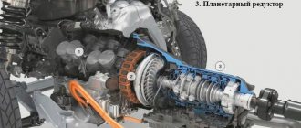
It is useful to include range-multipliers in the transmission of tracked agricultural equipment. An additional reduction gearbox allows you to increase the traction of agricultural machinery at critical moments, as well as more adequately control the vehicle when overcoming various natural and man-made obstacles. Structurally, such range multipliers differ from analogues installed on wheeled vehicles, but the operating principle remains unchanged. The use of a planetary turning mechanism in tracked vehicles does not affect the operation of the reduction gearbox: either one side of the drive gears or both tracks can slow down at the same time.
Changing the gear ratios of the multiplier
If the transfer case is equipped with a range multiplier (in other words, it has a reduction row of the transmission), then there is a natural desire to select such a gear ratio so that the car becomes “a completely all-terrain vehicle.” Of course that won't happen. The multiplier, or as modern journalists say, “lowered transmission range,” serves to reduce the rotation speed of the transfer case output shafts. Structurally, it can be included in the transfer case circuit or made as a separate unit.
Most low-power passenger cars were equipped with engines with a maximum crankshaft speed of about 4500 rpm. For these vehicles, the maximum speed in first gear should not exceed 25 km/h. This speed exactly corresponds to the maximum permissible number of revolutions of the engine crankshaft. The maximum torque of such engines is achieved at 3500-4000 rpm. and this corresponds to movement at speeds of 19.5-22 km/h. in first gear. At the same time, for off-road driving, the speed of 19-22 km/h turns out to be unacceptably high, and when you try to drive at a lower speed, the engine stalls due to high rolling resistance and low torque. To prevent the engine from stalling and the car to move at a low speed, drivers used clutch slipping, as a result of which the clutch friction linings wore out very quickly and the clutch failed.
By installing a multiplier in the transmission, the designers solved the problem of matching the maximum engine torque with the low speed of the vehicle on the road.
It should be taken into account that the reduction of the range multiplier is usually not very large - something like 2 times. In this case, the peak torque will occur at 9.5-11 km/h, and the maximum speed in first gear will not exceed 12.5 km/h.
When new powerful engines (especially diesel ones) appear in the arsenal of designers, the maximum torque of which begins at low speeds, i.e. those with “traction from the bottom”, the need for a range multiplier has practically disappeared. Indeed, if the engine pulls perfectly from 1800 rpm, then this will give a speed of about 10 km/h.
Now range multipliers are used as part of vehicle transmissions, the main purpose of which is constant operation in off-road conditions.
Types of reduction gears
Worm, less often cylindrical and planetary gears are used as reduction gears. The worm gear is one of the gearing gears with intersecting shaft axes. Movement in them is carried out according to the principle of a screw pair. Its main properties are low noise level due to the characteristics of the gearing, relatively low efficiency, small dimensions and large gear ratio. Compared to a helical gearbox, a worm gear provides better running smoothness. This type of transmission has a much greater potential for increasing torque and reducing rotation speed than gearboxes with other types of gears. Spur gears are used in mechanisms with parallel shafts. This type requires increased accuracy due to design features.
Gear drives are distinguished by their reliability and durability while maintaining the permissible load level; the disadvantages include the fact that at high rotation speeds such a mechanism has a high noise level and also cannot flexibly respond to changing loads. Planetary gears are also a type of gear. They have gears with movable axles. Such gears are lightweight, easy to assemble, produce less noise compared to conventional gears, and also have the ability to obtain large gear ratios. Disadvantages include a large number of parts, increased requirements for installation and manufacturing accuracy.
A gear is a mechanism for transmitting motion, in which force is transmitted from one element to another using teeth. A drive gear is a wheel that rotates under the influence of an external force, such as a hand or a motor. The drive wheel transmits external force to the driven wheel, which also begins to rotate.
- transmission of rotational motion between shafts, which may have parallel, intersecting and crossing axes;
- converting rotational motion into translational motion and vice versa.
The overdrive gear (multiplier) serves to increase the rotation speed. This reduces the force on the driven wheel.
A reduction gear (gearbox) serves to reduce the rotation speed. This increases the force on the driven wheel.
To obtain the gear ratio of two gears in mesh, you need to divide the number of teeth on the driven gear by the number of teeth on the drive gear. If the driven gear has 24 teeth and is driven by a 48-tooth gear, the gear ratio is 1:2. This means that the driven wheel will rotate twice as fast as the driving wheel. Bevel wheels are used where it is necessary to transmit torque at an angle. Such bevel wheels with circular teeth, for example, are used in cars, used to transmit torque from the engine to the wheels.
Number of gear teeth
An idler gear is a gear that is inserted as an intermediate gear between the drive and driven wheels in cases where they cannot engage or when it is necessary to change the direction of rotation of the driven shaft.
In ancient Egypt, gears were used in irrigation systems. At first, gears were made of wood, with inserted teeth made of hardwood - they were used until the beginning of the twentieth century, in particular, in water mills. Since ancient times, gears made of copper alloys have been used, and subsequently cast iron and steel.
Driving Features
In order to achieve better results in operation, you should follow some rules and recommendations:
be sure to pay attention to the tachometer, it is no less important than in a passenger car; drive the car smoothly, without exceeding the speed and without taking turns and sharp turns; uphill, always use the double-click system, it helps to save fuel and the transmission responds faster; If you get into a skid or the car is going off course, under no circumstances release the clutch or turn off the engine of the truck; If the car is stuck in mud or some other similar place, then you need to get out of there in second gear, at high speeds.
It is important for any driver that his equipment works without failures or malfunctions. There are many different situations possible on the road that require knowledge and high concentration of the driver
If you follow all the rules, driving will be enjoyable and without the risk of breakdowns.
Demultiplier as part of the turning mechanism of a tracked vehicle
Some types of planetary turning mechanisms for tracked vehicles, the design of which includes two two-speed differential gearboxes, make it possible to implement the range-multiplier function through simultaneous group (paired) switching of both gearboxes from one operating mode to another - from high gear to low gear. In this case, as in the case of the range multiplier that is part of the gearbox, the output torque increases with a simultaneous decrease in rotation speed. This option is only a consequence of the ability of such turning mechanisms to provide two gear ratios for maneuvering and is not formally a range-multiplier, although it can be used like one.
Contrary to the widespread belief that there is a range option in the turning mechanisms of the vast majority of tracked vehicles, in fact it was present only on relatively old equipment: British tanks, ,; ; ; ; Soviet tanks , , , , , , ; Soviet combat vehicles; Soviet tracked tractor. Also, some little used double-flow turning mechanisms on modern vehicles, similar to those on the Panther tank, have a similar option: sama, Soviet tracked tractor, Soviet combat tracked vehicles, etc.
Range gear transmission device
A lower gear will also help with long, steep climbs or when driving on ice. When downshifting, the engine is not overloaded, but the speed will not be high. Simply put, in a lower gear the “engine” will not overheat, and when driving off-road, your “iron horse” will not begin to slip due to the high torque.
We recommend reading: Financial assistance to low-income families in Arkhangelsk
Direct gearbox transmission is a mode in which the speed from the “engine” is transmitted without increasing or decreasing to the gearbox or drive shafts (torque from the engine is transmitted directly to the wheel axles). With direct transmission, torque and speed are transmitted without changes. The efficiency in this mode is much higher due to the fact that the torque does not pass through the intermediate shaft.
What is a demultiplier, its location
First, let's try to figure out what a gearbox range control is, in what cases it is needed and where it is installed.
The multiplier, which is sometimes called a reduction gearbox, is an additional box unit that allows you to get double the number of gears. Its task is to create intermediate driving modes with half the intermediate increase in power, which, if used correctly and in a timely manner, allows you to extend the service life of the entire transmission. Timely use should be understood as driving under load, when none of the available gears provides the optimal driving mode.
Simply put, the multiplier reduces the load on the gearbox gears, doubling the total number of gears.
This additional transmission unit is located behind the gearbox, occupying, in principle, little space and at the same time allowing for increased traction of the vehicle when engaging any direct transmission.
Let's explain this with a specific example. Let's say your car is heavily loaded and you are driving on a section with a very gentle and long incline. The fourth speed is unacceptable for you, since the car simply does not pull, and this mode of operation for the power unit is fraught with many troubles. At third speed, everything seems to be fine, there is enough traction, but you are forced to move at a lower speed than you could, since an increase in speed would lead to a sharp increase in fuel consumption. But if there was one more gear between third and fourth, this would allow the vehicle to move in an optimal mode for the power unit and transmission. That's what a range multiplier is for: it offers such an opportunity. The device is usually turned on using a button located on the gearshift lever. Note that the possibility of doubling speeds can be realized either by increasing or decreasing the gear ratio. Devices of the first type are called demultipliers, the second - dividers. In principle, their tasks are similar, but the implementation mechanism is different.
DEMULTIPLIER AND DIVIDER: FEATURES AND DIFFERENCES
The multiplier extends the service life of the gearbox due to the fact that it evenly increases power by reducing the load. Simply put, the divider doubles the number of gears, and thereby increases the traction force of the vehicle. It is turned on using a button on the lever or a toggle switch, thus selecting the lowest or highest gear shift row.
As I said above, the demultiplier and the divider are slightly different. The divider has direct and overdrive, and the range multiplier is just the opposite, direct and downshift. The demultiplier and divider can be installed together. If the box is 4-speed, then there will already be 16 gears, because just as a divider doubles gears, so does a multiplier. Direct transmission of the gearbox is a mode in which engine speed is transmitted without increasing or decreasing, that is, torque is transmitted from the motor to the wheel axles directly. The efficiency is very high because the torque does not pass through the intermediate shaft.
Overdrive, as many people know, is used to save fuel, also due to low engine speeds, in overdrive, engine wear and noise levels emanating from the engine are reduced. The driveshaft rotates faster than the engine crankshaft when overdrive is engaged.
In low gear, the engine produces high rpm at low speed. This transmission is needed to obtain higher torque in cases where the engine is heavy. For example, during a long steep climb, or when driving off-road. In a lower gear, the engine will not overheat when operating in harsh conditions. [2]
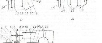
Figure 1 – Gearbox with range (Shift mechanism)
1, 5 – levers; 2 – earring; 3 – box shaft; 4 – clamp; 6 – damper;
The entire range mechanism consists of a shaft lever, a fork shaft and a fork. To switch between rows, a pneumatic drive of the switching mechanism is used. The drive itself includes: a valve block, a pneumatic cylinder and connecting hoses. Compressed air is supplied to the unit from the vehicle's pneumatic system. When a low gear or reverse gear is engaged, compressed air enters the pneumatic cylinder, and thus the switching occurs. When the remaining gears are engaged, the compressed air entering the pneumatic cylinder switches on a direct gear in the range multiplier.
The multiplier, like all parts of the gearbox, is lubricated with oil, which is poured into the crankcase. A mixed type lubrication system is used: pressure, splash and oil mist. The multiplier is lubricated under the pressure of the oil pump. [3]
To control the range multiplier and divider of a vehicle, in most cases, either automatic or semi-automatic switching systems are used, without any additional switch levers. If cross-country gears are needed, then an additional lever is used to control the range-shifter, and a mandatory complete stop of the vehicle is necessary in order to avoid unwanted, major transmission malfunctions. [4]
On boxes with a range multiplier it is strictly prohibited:
-switch from the highest gear range to the lowest at a speed of more than 30 km/h;
- drive in the neutral position of the gear shift lever;
- engage reverse gear while moving, when stopping incompletely.
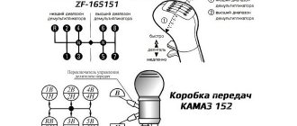
In the range-shifter, gear shifting occurs automatically, that is, the highest gear is engaged when the gearbox control lever is switched from fourth to fifth gear, and the lowest gear is engaged when switching from fifth to fourth gear.
When controlling a gearbox with a divider, to shift, you need to move the divider control toggle switch to the desired position, then after holding the clutch for a short time (1 second), you need to release the clutch pedal, and thus the gear will engage automatically.