Video: Crank mechanism (CSM). Basics
The crank mechanism is designed to convert the reciprocating motion of the piston into the rotational motion of the crankshaft.
The parts of the crank mechanism can be divided into:
- stationary - crankcase, cylinder block, cylinders, cylinder head, head gasket and pan. Typically the cylinder block is cast together with the upper half of the crankcase, which is why it is sometimes called a block crankcase.
- moving parts of the crankshaft - pistons, piston rings and pins, connecting rods, crankshaft and flywheel.
In addition, the crank mechanism includes various fasteners, as well as main and connecting rod bearings.
| How to care for CVS? |
| KShM malfunctions |
| KShM repair |
| Forces acting on the crankshaft parts |
| Diagnosis of CVS |
Cylinder
Cylinders are the guiding elements ⭐ of the crank mechanism. Pistons move inside them. The length of the cylinder generatrix is determined by the stroke of the piston and its dimensions. Cylinders operate under conditions of sharply changing pressure in the above-piston cavity. Their walls come into contact with flames and hot gases with temperatures up to 1500... 2500 °C.
Cylinders must be strong, rigid, heat and wear resistant with limited lubrication. In addition, the cylinder material must have good casting properties and be easy to machine. Typically, cylinders are made from special alloy cast iron, but aluminum alloys and steel can also be used. The inner working surface of the cylinder, called its mirror, is carefully processed and plated with chrome to reduce friction, increase wear resistance and durability.
In liquid-cooled engines, the cylinders may be cast together with the cylinder block or as separate liners installed in the block bores. Between the outer walls of the cylinders and the block there are cavities called a cooling jacket. The latter is filled with liquid that cools the engine. If the cylinder liner is in direct contact with the coolant with its outer surface, then it is called wet. Otherwise it is called dry. The use of replaceable wet liners makes engine repair easier. When installed in a block, wet liners are reliably sealed.
Air-cooled engine cylinders are cast individually. To improve heat dissipation, their outer surfaces are equipped with annular fins. On most air-cooled engines, the cylinders and their heads are secured with common bolts or studs to the top of the crankcase.
In a V-shaped engine, the cylinders of one row may be slightly offset relative to the cylinders of the other row. This is due to the fact that two connecting rods are attached to each crank of the crankshaft, one of which is intended for the piston of the right half of the block, and the other for the piston of the left half of the block.
Service Process
Like any part, the crankshaft requires special care. For inspection and repair, it must be removed. This is usually required during a major overhaul, for example, after a water hammer, during which the crankshaft may move.
To remove the crankshaft, it is necessary to dismantle the engine and its elements. Having turned the internal combustion engine over, mark the location of the main bearing caps, then remove them, lift the crankshaft and disconnect the rear sealing ring. After this, remove the liners from the cylinder blocks and covers. Thus, we have a disconnected crankshaft.
To check it, you need to wash the part with gasoline and dry it. An inspection is carried out for cracks, chips, and dents. If any are found, the part must be replaced.
By unscrewing the plugs, you can clean all the oil channels. The connecting rod harnesses are ground and polished, and the oil passages are cleaned again. Bearing shells, nose bearing, flywheel, oil seal and rubber seals must also be replaced if defects are detected.
After this, the engine is assembled in the reverse order of disassembly, having previously lubricated all parts. You also need to make sure that the part slides and rotates smoothly.
Cylinder block
A cylinder head is installed on the carefully processed upper plane of the cylinder block, which closes the cylinders from above. In the head above the cylinders there are recesses that form combustion chambers. For liquid-cooled engines, a cooling jacket is provided in the body of the cylinder head, which communicates with the cooling jacket of the cylinder block. With the valves located at the top, the head has seats for them, inlet and outlet channels, threaded holes for installing spark plugs (for gasoline engines) or injectors (for diesel engines), lubrication system lines, mounting and other auxiliary holes. The material for the block head is usually aluminum alloy or cast iron.
A tight connection between the cylinder block and the cylinder head is ensured using bolts or studs with nuts. To seal the joint in order to prevent leakage of gases from the cylinders and coolant from the cooling jacket, a gasket is installed between the cylinder block and the cylinder head. It is usually made of asbestos cardboard and lined with thin steel or copper sheet. Sometimes the gasket is rubbed with graphite on both sides to protect it from sticking.
The lower part of the crankcase, which protects the parts of the crank and other engine mechanisms from contamination, is usually called the sump. In relatively low-power engines, the pan also serves as a reservoir for engine oil. The pallet is most often cast or made from steel sheet by stamping. To eliminate oil leakage, a gasket is installed between the crankcase and the sump (on low-power engines, a sealant called “liquid gasket” is often used to seal this joint).
Signs of malfunctions in the operation of the crankshaft
For timely detection of failures and negative processes beginning to develop in the crank group, it is useful to know from external signs:
- Knocks in the engine, unusual sounds during acceleration. Ringing sounds are often caused by detonation phenomena. Incomplete combustion of fuel during the power stroke and its explosive combustion during the exhaust stroke lead to the accumulation of carbon deposits on the rings and the piston crown, deterioration of their cooling conditions and destruction. It is necessary to fill in high-quality fuel and check the operating parameters of the ignition system on the stand.
- Dull knocks indicate wear on the crankshaft journals. In this case, you should stop operating, grind the journals and replace the liners with thicker ones from the repair kit.
- A sound that “sings” at a high, loud note indicates the possible beginning of melting of the liners or a lack of oil when the speed increases. You also need to urgently go to the service center.
- Gray puffs of smoke from the exhaust pipe indicate excess oil in the working chamber. The condition of the rings should be checked and replaced if necessary.
- A drop in power can also be caused by ring coking and decreased compression.
If you notice these alarming symptoms, do not postpone your visit to the service center. A seized engine will cost much more, both in money and time.
Engine frame
The fixed parts of the crank mechanism connected to each other are the core of the engine, which absorbs all the main power and thermal loads, both internal (related to the operation of the engine) and external (due to the transmission and chassis). The force loads transmitted to the engine frame from the vehicle's supporting system (frame, body, housing) and back significantly depend on the method of engine mounting. Usually it is attached at three or four points so that loads caused by distortions of the supporting system that occur when the machine moves over uneven surfaces are not taken into account. The engine mounting must exclude the possibility of its displacement in the horizontal plane under the influence of longitudinal and transverse forces (during acceleration, braking, turning, etc.). To reduce vibration transmitted to the supporting system of the vehicle from a running engine, rubber cushions of various designs are installed between the engine and the sub-engine frame at the mounting points.
The piston group of the crank mechanism is formed by a piston assembly with a set of compression and oil rings, a piston pin and its fastening parts. Its purpose is to perceive gas pressure during the power stroke and transmit force to the crankshaft through the connecting rod, carry out other auxiliary strokes, and also seal the above-piston cavity of the cylinder to prevent gases from breaking through into the crankcase and the penetration of engine oil into it.
Features of engine operation. So you
A simplified diagram of the operation of the crankshaft is described above. In fact, in order to create the necessary conditions for normal combustion of the fuel mixture, preparatory steps are required - filling the combustion chamber with mixture components, compressing them and removing combustion products. These stages are called “engine strokes” and there are four of them - intake, compression, power stroke, exhaust. Of these, only the power stroke performs a useful function (it is during this stroke that energy is converted into movement), and the remaining strokes are preparatory. In this case, the execution of each stage is accompanied by a rotation of the crankshaft around the axis by 180 degrees.
The designers have developed two types of engines - 2-stroke and 4-stroke. In the first version, the strokes are combined (the power stroke is with exhaust, and the intake is with compression), so in such engines the full working cycle is performed in one full revolution of the crankshaft.
In a 4-stroke engine, each stroke is performed separately, therefore, in such engines, a full working cycle is performed in two revolutions of the crankshaft, and only one half-turn (at the “power stroke”) is performed due to the energy released during combustion, and the remaining 1.5 revolutions - thanks to the energy of the flywheel.
Piston
The piston is a metal glass of complex shape, installed in a cylinder with the bottom up. It consists of two main parts. The upper thickened part is called the head, and the lower guide part is called the skirt. The piston head contains a bottom 4 (Fig. a) and walls 2. Grooves 5 for compression rings are machined in the walls. The lower grooves have drainage holes 6 to drain oil. To increase the strength and rigidity of the head, its walls are equipped with massive ribs 3 that connect the walls and bottom with bosses in which the piston pin is installed. Sometimes the inner surface of the bottom is also ribbed.
The skirt has thinner walls than the head. In its middle part there are bosses with holes.
Rice. Designs of pistons with different bottom shapes (a-h) and their elements: 1 - boss; 2 — piston wall; 3 - rib; 4 — piston bottom; 5 — grooves for compression rings; 6 - drainage hole for oil drainage
The piston heads can be flat (see a), convex, concave and shaped (Fig. b-h). Their shape depends on the type of engine and combustion chamber, the adopted mixture formation method and the piston manufacturing technology. The simplest and most technologically advanced is the flat form. Diesel engines use pistons with concave and shaped bottoms (see Fig. e-h).
When the engine is running, the pistons heat up more than cylinders cooled by liquid or air, so the expansion of the pistons (especially aluminum ones) is greater. Despite the presence of a gap between the cylinder and the piston, jamming of the latter may occur. To prevent jamming, the skirt is given an oval shape (the major axis of the oval is perpendicular to the piston pin axis), the diameter of the skirt is increased compared to the diameter of the head, the skirt is cut (most often a T- or U-shaped cut is made), and compensation inserts are poured into the piston to limit thermal expansion skirts in the plane of swing of the connecting rod, or forcefully cool the internal surfaces of the piston with jets of engine oil under pressure.
A piston subjected to significant force and thermal loads must have high strength, thermal conductivity and wear resistance. In order to reduce inertial forces and moments, it must have a low mass. This is taken into account when choosing the design and material for the piston. Most often the material is aluminum alloy or cast iron. Sometimes steel and magnesium alloys are used. Promising materials for pistons or their individual parts are ceramics and sintered materials that have sufficient strength, high wear resistance, low thermal conductivity, low density and a small coefficient of thermal expansion.
Working conditions and requirements for the connecting rod [edit | edit code ]
The connecting rod in modern high-speed engines perceives alternating voltages billions of times (this number depends on the speed and service life of the internal combustion engine). The requirements are:
- sufficient fatigue strength to avoid failure;
- rigidity to prevent loss of stability of the rod during compression (taking into account possible one-time overloads in accidents);
- minimum weight to reduce dynamic loads on the crankshaft journals and reduce the mass of counterweights, as well as the flywheel;
- manufacturability and simplicity of design, also determined by the capabilities of machine processing;
- minimum costs for the material, however, ensuring 90% hardenability of the section (or refusal of hardening, if this is not possible on large-sized engines) [6].
Piston rings
Piston rings provide a tight, moving connection between the piston and the cylinder. They prevent the breakthrough of gases from the above-piston cavity into the crankcase and the entry of oil into the combustion chamber. There are compression and oil scraper rings.
Compression rings (two or three) are installed in the upper grooves of the piston. They have a cut called a lock and can therefore spring back. In the free state, the diameter of the ring should be slightly larger than the diameter of the cylinder. When such a ring is inserted into the cylinder in a compressed state, it creates a tight connection. In order to ensure that the ring installed in the cylinder can expand when heated, there must be a gap of 0.2...0.4 mm in the lock. In order to ensure good running-in of compression rings, rings with a tapered outer surface, as well as twisting rings with a chamfer on the edge on the inside or outside, are often used on cylinders. Due to the presence of a chamfer, such rings, when installed in a cylinder, are skewed in cross-section, fitting tightly to the walls of the grooves on the piston.
scraper rings (one or two) remove oil from the cylinder walls, preventing it from entering the combustion chamber. They are located on the piston under the compression rings. Typically, oil scraper rings have an annular groove on the outer cylindrical surface and radial through slots to drain oil, which passes through them to the drainage holes in the piston (see Fig. a). In addition to oil scraper rings with slots for oil drainage, composite rings with axial and radial expanders are used.
To prevent gas leakage from the combustion chamber into the crankcase through the locks of the piston rings, it is necessary to ensure that the locks of adjacent rings are not located on the same straight line.
Piston rings operate under difficult conditions. They are exposed to high temperatures, and lubrication of their outer surfaces, moving at high speed along the cylinder mirror, is not enough. Therefore, high demands are placed on the material for piston rings. Most often, high-grade alloy cast iron is used for their manufacture. Upper compression rings, which operate under the most severe conditions, are usually coated on the outside with porous chrome. Composite oil scraper rings are made of alloy steel.
OPERATING PRINCIPLE OF THE MECHANISM
We will consider the operating principle of the crank mechanism in a simplified manner using the example of a single-cylinder engine. This engine includes:
- crankshaft with two main journals and one crank;
- connecting rod;
- and a set of CPG parts, including a liner, piston, piston rings and pin.
Ignition of the combustible mixture occurs when the volume of the combustion chamber is minimal, and this is ensured by the maximum lifting of the piston inside the liner (top dead center - TDC). In this position, the crank also “looks” up. During combustion, the energy released pushes the piston down, this movement is transmitted through the connecting rod to the crank, and it begins to move downward in a circle, while the main journals rotate around their axis.
When the crank is rotated 180 degrees, the piston reaches bottom dead center (BDC). After reaching it, the mechanism operates in reverse. Due to the accumulated kinetic energy, the flywheel continues to rotate the crankshaft, so the crank rotates and pushes the piston up through the connecting rod. Then the cycle repeats completely.
If we consider it more simply, then one half-turn of the crankshaft is carried out due to the energy released during combustion, and the second - due to the kinetic energy accumulated by the flywheel. Then the process is repeated again.
Piston pin
The piston pin serves to articulate the piston with the connecting rod. It is a tube passing through the upper head of the connecting rod and installed at its ends into the piston bosses. The piston pin is secured to the bosses by two retaining spring rings located in special grooves of the bosses. This fastening allows the finger (in this case it is called a floating finger) to rotate. Its entire surface becomes working, and it wears out less. The pin axis in the piston bosses can be shifted relative to the cylinder axis by 1.5...2.0 mm in the direction of the greater lateral force. This reduces piston knock in a cold engine.
Piston pins are made of high quality steel. To ensure high wear resistance, their outer cylindrical surface is hardened or carburized, and then ground and polished.
The piston group consists of a fairly large number of parts (piston, rings, pin), the mass of which can fluctuate for technological reasons; within certain limits. If the difference in the mass of the piston groups in different cylinders is significant, then additional inertial loads will arise during engine operation. Therefore, piston groups for one engine are selected so that they differ insignificantly in weight (for heavy engines by no more than 10 g).
The connecting rod group of the crank mechanism consists of:
- connecting rod
- upper and lower connecting rod heads
- bearings
- connecting rod bolts with nuts and elements for their fixation
What is a crankshaft and why is a crank mechanism needed?
If there is one thing that is strongly associated with any car, it is the engine mechanism. Oddly enough, the principle of its operation has changed little since Karl Benz patented his first car 120 years ago. The system became more complex, acquired complex electronics, and improved, but the crank mechanism (CCM) remained the most recognizable “portrait” of any engine.
- What is a KShM and why is it needed?
- KShM device
- Mobile (working) group of KShM
- Fixed group KShM
- Operating principle of KShM
- Basic faults
- Conclusion
connecting rod
The connecting rod connects the piston to the crank of the crankshaft and, transforming the reciprocating motion of the piston group into the rotational movement of the crankshaft, makes a complex movement, while being subjected to alternating shock loads. The connecting rod consists of three structural elements: rod 2, upper (piston) head 1 and lower (crank) head 3. The connecting rod rod usually has an I-section. To reduce friction, a bronze bushing 6 with a hole for supplying oil to the rubbing surfaces is pressed into the upper head to reduce friction. The lower head of the connecting rod is split to allow assembly with the crankshaft. For gasoline engines, the head connector is usually located at an angle of 90° to the axis of the connecting rod. In diesel engines, the lower head of the connecting rod 7, as a rule, has an oblique connector. The lower head cover 4 is attached to the connecting rod with two connecting rod bolts, precisely matched to the holes in the connecting rod and the cover to ensure high precision assembly. To prevent the fastening from loosening, the bolt nuts are secured with cotter pins, lock washers or lock nuts. The hole in the lower head is bored together with the cover, so the connecting rod covers cannot be interchangeable.
Rice. Parts of the connecting rod group: 1 - upper head of the connecting rod; 2 - rod; 3 — lower head of the connecting rod; 4 — lower head cover; 5 — liners; 6 — bushing; 7 — diesel connecting rod; S - main connecting rod of the articulated connecting rod unit
To reduce friction in the connection of the connecting rod with the crankshaft and facilitate engine repair, a connecting rod bearing is installed in the lower head of the connecting rod, which is made in the form of two thin-walled steel liners 5 filled with an antifriction alloy. The inner surface of the liners is precisely adjusted to the crankshaft journals. To fix the liners relative to the head, they have bent antennae that fit into the corresponding grooves in the head. The supply of oil to the rubbing surfaces is provided by annular grooves and holes in the liners.
To ensure good balance of the parts of the crank mechanism, the connecting rod groups of one engine (as well as the piston ones) must have the same mass with its corresponding distribution between the upper and lower heads of the connecting rod.
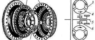
V-twin engines sometimes use articulated connecting rod assemblies, consisting of paired connecting rods. The main connecting rod 8, which has a conventional design, is connected to the piston of one row. An auxiliary trailing connecting rod, connected by the upper head to a piston of another row, is pivotally attached with a pin to the lower head of the main connecting rod by the lower head.
KShM device
The cylinder block is the main part of the engine to which all mechanisms and parts are attached. Cylinder blocks are cast from cast iron or aluminum alloy. The same casting is used to make the crankcase and the walls of the cooling jacket surrounding the engine cylinders. Insert liners are installed into the cylinder block. The sleeves are either “wet” (cooled by liquid) or “dry”. Many modern engines use linerless blocks. The inner surface of the liner (cylinder) serves as a guide for the pistons.
The cylinder block is closed from above with one or two (in V-shaped engines) cylinder heads made of aluminum alloy. The cylinder head (cylinder head) contains combustion chambers, in which there are threaded holes for spark plugs (in diesel engines, for glow plugs). ICE heads with direct injection also have an opening for injectors. To cool the combustion chambers, a special jacket is made around them. The parts of the gas distribution mechanism are fixed to the cylinder head. The cylinder head has inlet and outlet channels and installed insert seats and valve guides. To create a seal, a gasket is installed between the block and the cylinder head, and the head is secured to the cylinder block with studs and nuts. The cylinder head is closed from above with a cover. An oil-resistant gasket is installed between them.
Cylinder block
Sectional view of a cylinder block
Cylinder head
KShM details
The piston receives gas pressure during the power stroke and transmits it through the piston pin and connecting rod to the crankshaft. The piston is an inverted cylindrical glass cast from an aluminum alloy. At the top of the piston there is a head with grooves into which the piston rings are inserted. Below the head there is a skirt that guides the movement of the piston. The piston skirt has bosses with holes for the piston pin.
When the engine is running, the piston, heating up, will expand and, if there is no necessary clearance between it and the cylinder wall, it will jam in the cylinder. If the gap is too large, then some of the exhaust gases will break into the crankcase. This will lead to a drop in cylinder pressure and a decrease in engine power. Therefore, the piston head is made of a smaller diameter than the skirt, and the skirt itself in cross section is not made of a cylindrical shape, but in the form of an ellipse with a larger axis in a plane perpendicular to the piston pin. There is a cut on the piston skirt. Due to the oval shape and cut of the skirt, jamming of the piston is prevented when the engine is warm. The general design of the pistons is fundamentally the same, but their designs may differ depending on the characteristics of a particular engine.
Piston rings are divided into compression and oil scraper rings. Compression rings seal the piston in the cylinder and serve to reduce the breakthrough of gases from the cylinders into the crankcase, and oil scraper rings remove excess oil from the cylinder walls and prevent oil from penetrating into the combustion chamber. Rings made of cast iron or steel have a cut (lock). The number of rings in different engines may vary.
The piston pin pivotally connects the piston to the upper head of the connecting rod. The finger is made in the form of a hollow cylindrical rod, the outer surface of which is hardened by high-frequency currents. The axial movement of the pin in the piston bosses is limited by split steel rings.
rod is used to connect the crankshaft to the piston. The connecting rod consists of an I-section steel rod, an upper one-piece head and a lower split head. The upper head has a piston pin, and the lower head is mounted on the crankpin of the crankshaft. To reduce friction, a bushing is pressed into the upper head of the connecting rod, and thin-walled liners are installed into the lower, consisting of two parts. Both parts of the lower head are fastened with two bolts and nuts. Oil is supplied to the connecting rod heads when the engine is running. In V-shaped engines, two connecting rods are attached to one crankpin of the crankshaft.
The crankshaft is made of steel or ductile iron. It consists of connecting rod and main ground journals, cheeks and counterweights. The rear part of the shaft is made in the form of a flange to which the flywheel is bolted. A belt pulley and a camshaft drive sprocket are attached to the front end of the crankshaft. A torsional vibration damper can be integrated into the pulley. The most common design consists of two metal rings connected through an elastic medium (rubber-elastomer, viscous oil).
The number and location of connecting rod journals depend on the number of cylinders and their location. The connecting rod journals of the crankshaft of a multi-cylinder engine are made in different planes, which is necessary for uniform alternation of power strokes in different cylinders. The main and connecting rod journals are connected to each other by cheeks. To reduce the centrifugal forces created by the cranks, counterweights are made on the crankshaft, and the connecting rod journals are made hollow. The surface of the main and connecting rod journals is hardened with high frequency currents. There are channels in the necks and cheeks for supplying oil. Each crankpin has a cavity that serves as a dirt trap. Oil enters the dirt traps from the main journals and when the shaft rotates, dirt particles in the oil are separated from the oil under the influence of centrifugal forces and settle on the walls. Cleaning of dirt traps is carried out through screw plugs wrapped in their ends only when disassembling the engine. The movement of the shaft in the longitudinal direction is limited by thrust washers. Where the crankshaft exits the engine crankcase there are oil seals and gaskets that prevent oil leakage.
When the engine is running, the loads on the connecting rods and main journals of the crankshaft are very high. To reduce friction, the shaft journals are located in sliding bearings, which are made in the form of metal liners coated with an antifriction layer. The inserts consist of two halves. The connecting rod bearings are installed in the lower split head of the connecting rod, and the main bearings are installed in the block and bearing cap. The main bearing caps are bolted to the cylinder block and locked to prevent self-unscrewing. To prevent the liners from turning, protrusions are made in them, and corresponding ledges are made in the covers, saddles and connecting rod heads.
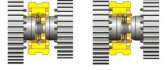
The flywheel reduces the unevenness of the engine, makes it easier to start and promotes smooth starting of the car. The flywheel is made in the form of a massive cast-iron disk and is attached to the crankshaft flange with bolts and nuts. During manufacture, the flywheel is balanced together with the crankshaft. To ensure that the balancing is not disturbed when disassembling the engine, the flywheel is installed on asymmetrically located pins or bolts. This prevents it from being installed incorrectly. In some engines, to reduce torsional vibrations transmitted to the gearbox, dual-mass flywheels are used, which are two disks elastically connected to each other. The disks can move relative to each other in the radial direction. Marks are placed on the flywheel rim, along which the piston of the first cylinder is installed in the top line. when installing the ignition or when the fuel supply starts (for diesel engines). A ring gear is also attached to the rim, designed to engage with the starter bendix.
To reduce vibration, in-line engines use balancer shafts located under the crankshaft in the oil pan.
Flywheel
Dual mass flywheel
Balancer shafts
Oil pan
The engine crankcase is cast integrally with the cylinder block. Parts of the crank and gas distribution mechanisms are attached to it. To increase rigidity, ribs are made inside the crankcase, into which the seats of the crankshaft main bearings are bored. The bottom of the crankcase is closed with a pan stamped from a thin steel sheet. The pan is used as an oil reservoir and protects engine parts from contamination. There is a plug at the bottom of the pan for draining engine oil. The pan is attached to the crankcase with bolts. To prevent oil leakage, a gasket is installed between them.
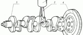
Crankshaft
The crankshaft , connected to the piston through a connecting rod, perceives the forces acting on the piston. A torque is generated on it, which is then transmitted to the transmission, and is also used to drive other mechanisms and units. Under the influence of inertial forces and gas pressure that sharply change in magnitude and direction, the crankshaft rotates unevenly, experiencing torsional vibrations, being subjected to twisting, bending, compression and tension, and also receiving thermal loads. Therefore, it must have sufficient strength, rigidity and wear resistance with a relatively low weight.
Crankshaft designs are complex. Their shape is determined by the number and arrangement of cylinders, the order of operation of the engine and the number of main bearings. The main parts of the crankshaft are main journals 3, connecting rod journals 2, cheeks 4, counterweights 5, front end (toe 1) and rear end (shank 6) with a flange.
The lower heads of the connecting rods are attached to the connecting rod journals of the crankshaft. The main journals of the shaft are installed in the bearings of the engine crankcase. The main and connecting rod journals are connected using cheeks. A smooth transition from the journals to the cheeks, called a fillet, avoids stress concentrations and possible breakdowns of the crankshaft. Counterweights are designed to unload the main bearings from the centrifugal forces that arise on the crankshaft during its rotation. They are usually made as one piece with the cheeks.
To ensure normal engine operation, engine oil must be supplied under pressure to the working surfaces of the main and connecting rod journals. Oil flows from holes in the crankcase to the main bearings. Then it reaches the connecting rod bearings through special channels in the main journals, cheeks and crankpins. For additional centrifugal oil purification, the connecting rod journals have dirt-collecting cavities closed with plugs.
Crankshafts are made by forging or casting from medium-carbon and alloy steels (high-quality cast iron can also be used). After mechanical and thermal treatment, the main and connecting rod journals are subjected to surface hardening (to increase wear resistance), and then ground and polished. After processing, the shaft is balanced, i.e., such a distribution of its mass relative to the axis of rotation is achieved in which the shaft is in a state of indifferent equilibrium.
Main bearings use thin-walled wear-resistant liners similar to the liners of connecting rod bearings. To absorb axial loads and prevent axial displacement of the crankshaft, one of its main bearings (usually the front one) is made thrust.
Note.
A considerable proportion of attached motor equipment is mounted on the cylinder block, and when the engine is turned on, it works with it as a single unit.
As for the purpose and principle of operation of the piston and other parts of the piston group, we have already discussed this above. Let us only recall that under the force of powerful pressure that is formed in the cylinder after combustion of the working mixture, the piston moves down and transmits its movement through the connecting rod (on which it is installed) to the crankshaft, forming the very torque with which the car is driven into movement.
Know that the internal combustion engine operates in a rather harsh regime. At idle speed (that is, when the engine is running, but the car is stationary in neutral), the crankshaft rotates at a speed of 600-900 revolutions per minute (or about 10-16 revolutions per second). When driving at medium speed, the engine works even more intensely, and the crankshaft rotates at a speed of 2000 to 3000 rpm. And in modern sports cars, the crankshaft rotation speed can exceed 200 revolutions per second (10,000 - 13,000 revolutions per minute).
Consequently, the pistons in the cylinders move up and down very quickly. We have already noted earlier that in one full revolution of the crankshaft, the piston manages to cover the distance between TDC and BDC twice. So: he performs these movements literally in a fraction of a second. If we add to this powerful pressure, as well as high temperature in each cylinder, then the operating conditions of the internal combustion engine can be called extreme.
Flywheel
The flywheel is attached to the crankshaft shank flange. It is a carefully balanced cast iron disk of a certain mass. In addition to ensuring uniform rotation of the crankshaft, the flywheel helps overcome compression resistance in the cylinders when starting the engine and short-term overloads, for example, when starting a vehicle. A ring gear is attached to the flywheel rim to start the engine from the starter. The surface of the flywheel that comes into contact with the clutch driven disc is ground and polished.
Rice. Crankshaft: 1 - toe; 2 — connecting rod journal; 3 - molar neck; 4 - cheek; 5 - counterweight; 6 - shank with flange
What is a crankshaft
The crankshaft is a mechanical part of a car engine, which is an intermediate link that converts the thermal energy of burned fuel into the mechanical energy of wheel rotation. In appearance, it is a shaft made of a steel alloy with many connecting rod journals, which are connected to each other by a knee journal. The number of necks and elbows corresponds to the number of cylinders in the engine, their location, and shape. The journals are connected to the pistons through connecting rods, which, moving back and forth, set the shaft in motion.
If the crankshaft has connecting rod journals on both sides of the crankshaft, it is called full support. If they are located only on one side - incomplete support.
The crankshaft is made from high-wear carbon or alloy steel (for sports cars, luxury models and high-performance vehicles) or modified cast iron (for standard production models) by casting or extrusion. Molybdenum, chromium and other metals are used to alloy steel, significantly increasing the strength of the alloy.
In most engines, the crankshaft is located in the lower part, above the crankcase; in opposed engines, it is located higher, in the center of the engine.
This is interesting: Adjusting the carburetor yourself