The sequence of completing the task of disassembling the crankshaft and timing gear.
1. Study the layout and operation of the crankshaft and timing gear on the poster and on the engine.
2. Perform partial disassembly and reassembly, study the design and operation of the KShM assembly units.
Disassemble the engine crankshaft:
• remove the suction (intake) manifold, gaskets;
• remove the block head cover and the rocker arm axle assembly from one row;
• remove the rods, using a special puller, remove the pushers;
• remove the cylinder head, head gasket;
• perform the last three operations on another bank of cylinders;
• remove the front cover of the timing gears and the oil deflector; • unscrew the flange mounting bolts (through the hole in the gear) and remove the shaft with the gear;
• unscrew the nuts securing the covers of the main bearings of the crankshaft of the first and fifth cylinders, unscrew the nuts and remove the covers together with the liners;
• unscrew the locknuts and nuts from the connecting rod cap bolts of the first and fifth cylinders, remove the caps with liners;
• remove the pistons with connecting rods from these cylinders;
• clamp the connecting rod in a vice and remove the retaining rings from the grooves of the bosses;
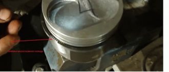
• clamp the piston in a vice through wooden jaws and remove the compression rings and two annular disks of the oil scraper ring from it using a special device;
• disassemble the oil scraper ring expanders;
• remove the piston pin retaining ring and press out the pin;
• carry out diagnostics of all removed parts for defects, i.e. carry out defect detection of removed parts.
Assemble the 3M3-53 engine crankshaft in the following order:
• reinstall the covers of the first and fifth main bearings of the crankshaft, complete with liners, after lubricating them with engine oil;
• tighten the cover fastening nuts first with a socket wrench and then finally with a torque wrench (moment of force 100.110 N * m) and pin the nuts with new wire with a diameter of 1.8 mm;
• connect the piston to the connecting rod using a piston pin, having previously heated the piston to 60 °C in clean engine oil. Connect the connecting rods of the right row to the pistons so that the stamped number on the connecting rod rod and the inscription “Front” on the piston are located on opposite sides; for connecting rods of the left row - on one;
• lock the piston pins with a ring;
• install the compression rings on the piston with the internal recess upward, and the locks should be positioned at 180° relative to each other; • install the oil scraper ring and position the locks of the annular disks at 180° from one another, and the radial and axial expanders at an angle of 90° to them and in opposite directions;
• lubricate the piston with engine oil and, using a special tool, compress the piston rings and insert the piston into the cylinder liner with the inscription “Front” to the toe of the crankshaft;
• lubricate the connecting rod bearing with engine oil and install the connecting rod on the crankshaft journal so that the number on the connecting rod rod coincides with the mark (protrusion) on the connecting rod cover;
• tighten the connecting rod nuts first with a socket wrench and then with a torque wrench (torque 68.75 Nm). Tighten the locknuts all the way and finally tighten them one or two turns.
3. Perform partial disassembly and reassembly, study the design and operation of the timing assembly units.
Disassemble and reassemble the engine timing belt:
• remove all parts from the dismantled rocker arm axle, arranging them in the order of removal, so that subsequent assembly can be carried out quickly and without errors;
• using a device, compress the valve spring and remove the crackers;
• remove the guide bushing of the cotters, the spring plate, the oil seal, and the spring from the valve stem;
• turn the head and pull the valve out of the guide;
• perform defect detection of removed parts;
• assemble the timing belt in reverse order;
• when installing the camshaft into the cylinder block, install the crankshaft and camshaft gears according to the marks;
• tighten the cylinder head nuts in two steps and finally with a torque wrench (torque 73.78 N m); • moment of force when tightening the intake manifold nuts 15. 20 N m.
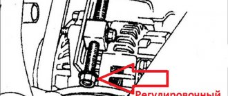
4. Adjust the thermal clearances.
5. Check and adjust the timing belt tension.
did not you find what you were looking for? Use the search:
Source
1. Study the design of the crankshaft engine of the ZMZ-53 engine using the textbook, use Fig. 1.1.
2. Make a map of the sequence of operations for disassembling and assembling the engine according to the form˸
| No. | Sequence of operations | Tool, device | Specifications and instructions |
3.Procedure for disassembling the crankshaft of the ZMZ-53 engine˸
remove the suction (intake) manifold, gaskets;
remove the block head cover and the rocker arm axle assembly from one row;
remove the rods, use a special puller to remove the pushers;
remove the cylinder head, head gasket;
perform the last three operations on another bank of cylinders;
remove the front timing gear cover and oil deflector;
a) b)
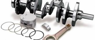
Rice. 1.1. Connecting rod and piston group˸
a, b - pistons of the ZMZ-53 engine assembled with connecting rods, installed respectively in the cylinders of the right and left rows; 1 - retaining ring; 2 — piston pin; 3 — oil scraper rings; 4 — piston crown with arrow marking; 5 — compression rings; 6 - piston; 7 — connecting rod; 8 — mark on the connecting rod rod; 9 — connecting rod bolt; 10 — connecting rod cover; 11 - castle nut; 12, 15—marks (protrusions) on the connecting rod covers; 13 — inscription on the piston; 14 - number on the connecting rod
Unscrew the flange mounting bolts (through the hole in the gear) and remove the shaft with the gear;
Unscrew the nuts securing the caps of the main bearings of the crankshaft of the first and fifth cylinders, unscrew the nuts and remove the caps together with the liners;
unscrew the locknuts and nuts from the connecting rod cap bolts of the first and fifth cylinders, remove the caps with liners;
remove the pistons with connecting rods from these cylinders;
clamp the connecting rod in a vice and remove the retaining rings from the grooves of the bosses;
clamp the piston in a vice through wooden jaws and remove the compression rings and two annular disks of the oil scraper ring from it using a special device;
disassemble the oil scraper ring expanders;
remove the piston pin retaining ring and press out the pin;
carry out diagnostics of all removed parts for defects, i.e. perform defect detection of removed parts.
4. Assembly procedure for the ZMZ-53 engine crankshaft˸
Replace the covers of the first and fifth main bearings of the crankshaft assemblies with liners, having previously lubricated them with engine oil;
tighten the nuts securing the covers first with a socket wrench and then finally with a torque wrench (torque 100... 110 Nm) and secure the nuts with new Æ 1.8 mm wire;
Connect the piston to the connecting rod using a piston pin, after preheating the piston to 60 °C in clean engine oil. Connect the connecting rods of the right row to the pistons so that the stamped number on the connecting rod rod and the inscription “Front” on the piston are located on opposite sides; for connecting rods of the left row - on one;
lock the piston pins with a ring;
install the compression rings on the piston with the internal recess upwards, and the locks should be located one relative to the other through 180°;
install the oil scraper ring and position the locks of the annular disks at 180° from one another, and the radial and axial expanders at an angle of 90° to them and in opposite directions;
Engine timing belt assembly
Assembly of crank mechanisms
Often, home mechanics have to deal with the repair of steam engines, internal combustion engines, compressors, and piston pumps.
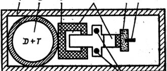
The operation of all these mechanisms is based on converting the translational movement of the piston into the rotational movement of the shaft, and vice versa: they convert the rotational movements of the shaft into the translational movements of the piston. Such engines are called crank mechanisms (Fig. 68).
Rice. 68. Assembly of the crank mechanism: a – crank mechanism: 1 – piston; 2 – connecting rod; 3 – crankshaft; 4 – flywheel.
Rice. 68 (continued). Assembling the crank mechanism: b – connecting rod and piston group before assembly: 1 – piston; 2 – piston rings; 3 – piston pin; 4 – connecting rod; 5 – upper liner; 6 – lower liner; 7 – bolt; 8 – nut with cotter pin; 9 – lower head cover; 10 – bushing; c – pliers for mounting piston rings.
The assembly units of the crank mechanism are:
– the crankshaft (crank or crank disk depending on the type of engine) is the most critical part of the mechanism; it is he who converts the translational movements of the piston group into rotational ones (and vice versa);
– the flywheel, having a large mass and possessing great inertia, makes it easier to start the engine, makes the transition from one rotation frequency (speed) to another smoother, reduces the unevenness of shaft rotation and removes the pistons from “dead spots” during operation of the mechanism;
– a connecting rod of the mechanism that connects the crankshaft (crank or crank disk) to the piston group;
– piston group – this element of the mechanism transmits the axial force created in the cylinder by steam or gas pressure (in internal combustion engines and steam boilers), or, on the contrary, receives axial forces from shaft rotation, compressing and supplying air, gas or liquid (in compressors and piston pumps).
The assembly of the crank mechanism occurs in stages: the piston is assembled separately, the connecting rod is pre-assembled, the piston is connected to the connecting rod, and the connecting rod and piston group is installed on the shaft.
Assembling the piston begins with selecting it according to the cylinder liners, and the main thing here is to ensure the necessary tightness (the piston, in addition to converting one type of energy into another, must prevent the penetration of oil from the crankcase into the cylinder, and also remove heat, which occurs during fuel combustion; at the same time, the piston should not jam and there should be a lubricating layer between the cylinder liner and the piston). The necessary tightness can be achieved by correct selection of the gap between the cylinder walls and the piston, and this gap should be unequal along the height of the piston due to its uneven heating (and, accordingly, expansion) during operation. The smallest gap in a cold state should be on the lower part of the piston, which is the centering part for the piston. The approximate clearance is: for cast iron pistons - from 0.001 to 0.002 cylinder diameters, for aluminum pistons - from 0.002 to 0.004 diameters.
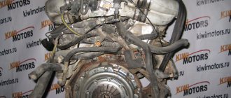
Dismantling and assembling the crankshaft of a carburetor internal combustion engine.
Purpose of the work: to study the main malfunctions of internal combustion engine systems,
— study methods for diagnosing internal combustion engine systems.
— acquire practical skills in diagnosing internal combustion engine systems.
Equipment: VAZ car engine assembly; KShM parts; cylinder liner pullers, devices for disassembling cylinder heads; stand for engine disassembly, press, sets of open-end and socket wrenches, torque handle.
Contents of the work: study the mechanisms included in the engine, disassembling the engine. Using a poster and an album, study the group of fixed and moving parts that make up the CVS.
Description of work:
The most typical malfunctions of the CV engine are: burning, wear and breakage of piston rings, wear of pistons, cylinders, main and connecting rod bearings, failure of the cylinder head gasket seal, breakage of the cylinder head mounting studs and damage to the threads on them, carbon formation in the combustion chambers.
The operation of all these mechanisms is based on converting the translational movement of the piston into the rotational movement of the shaft, and vice versa: they convert the rotational movements of the shaft into the translational movements of the piston. Such engines are called crank mechanisms.
Rice. Assembly of the crank mechanism: a – crank mechanism: 1 – piston; 2 – connecting rod; 3 – crankshaft; 4 – flywheel.
Rice. (continuation). Assembling the crank mechanism: b – connecting rod and piston group before assembly: 1 – piston; 2 – piston rings; 3 – piston pin; 4 – connecting rod; 5 – upper liner; 6 – lower liner; 7 – bolt; 8 – nut with cotter pin; 9 – lower head cover; 10 – bushing; c – pliers for mounting piston rings.
The assembly units of the crank mechanism are:
– the crankshaft (crank or crank disk depending on the type of engine) is the most critical part of the mechanism; it is he who converts the translational movements of the piston group into rotational ones (and vice versa);
– the flywheel, having a large mass and possessing great inertia, makes it easier to start the engine, makes the transition from one rotation frequency (speed) to another smoother, reduces the unevenness of shaft rotation and removes the pistons from “dead spots” during operation of the mechanism;
– a connecting rod of the mechanism that connects the crankshaft (crank or crank disk) to the piston group;
– piston group – this element of the mechanism transmits the axial force created in the cylinder by steam or gas pressure (in internal combustion engines and steam boilers), or, on the contrary, receives axial forces from shaft rotation, compressing and supplying air, gas or liquid (in compressors and piston pumps).
The assembly of the crank mechanism occurs in stages: the piston is assembled separately, the connecting rod is pre-assembled, the piston is connected to the connecting rod, and the connecting rod and piston group is installed on the shaft.
Assembling the piston begins with selecting it according to the cylinder liners, and the main thing here is to ensure the necessary tightness (the piston, in addition to converting one type of energy into another, must prevent the penetration of oil from the crankcase into the cylinder, and also remove heat, which occurs during fuel combustion; at the same time, the piston should not jam and there should be a lubricating layer between the cylinder liner and the piston). The necessary tightness can be achieved by correct selection of the gap between the cylinder walls and the piston, and this gap should be unequal along the height of the piston due to its uneven heating (and, accordingly, expansion) during operation. The smallest gap in a cold state should be on the lower part of the piston, which is the centering part for the piston. The approximate clearance is: for cast iron pistons - from 0.001 to 0.002 cylinder diameters, for aluminum pistons - from 0.002 to 0.004 diameters.
Rules for assembling KShM parts
When assembling components and parts of crank mechanism groups, you must adhere to certain rules and requirements, otherwise you can damage the engine during startup and operation.
The conditions and requirements for installing parts are determined by the features of their design, which were described in the relevant sections of the site.
For example, the piston of a modern piston internal combustion engine has a number of structural elements that cannot always be detected by simple inspection. In particular, the hole for the pin is shifted relative to the central axis of symmetry of the piston, and on its skirt there are cuts and grooves, which, if the piston is installed incorrectly, can cause its destruction and breakage.
In addition, parts of multi-cylinder engines are selected using a selection method based on size and weight in order to reduce additional inertial loads. For these reasons, the installation of components and parts of the crankshaft requires care and knowledge of the rules for their assembly.
Features of assembling pistons and cylinder liners
Pistons and cylinder liners are installed completely in accordance with the dimensions of the parts. The masses of different pistons should not differ from each other by more than 2...8 g. Pistons are installed with a mark (usually in the form of an arrow) on the piston bottom forward in the direction of travel. On some pistons, the inscription “Front” is used instead of a mark.
The precise installation of the piston during assembly is caused by the loosening of the skirt with a slot on one side and the displacement of the piston pin from the cylinder axis to the side. When installing pistons that have recesses for the valves, it is necessary to ensure the correct location of the recesses, otherwise you can bend the valve stems when starting the engine.
When installing liners, the rubber O-rings must be replaced with new ones.
The piston, pin and connecting rod are assembled from parts of only one size group. To avoid scuffing on the mating surfaces, assembly of the pin with the piston is carried out after heating the piston in clean oil to a temperature of 80...100 ˚C.
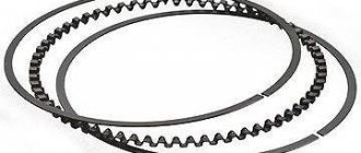
Features of piston ring assembly
Compression rings are installed on the piston so that the groove on the inner surface of the rings faces upward (Fig. 1). In this case, the joints of the ring locks must be offset relative to each other by 180˚ with two and 120˚ with three compression rings.
When installing composite oil scraper rings, the locks of their flat disks are located at an angle of 180˚ to one another and at an angle of 90˚ to the locks of the compression rings. In this case, the locks of the axial 3 and radial 4 expanders should be located at an angle of 90˚ to them.
When installing a cast iron oil scraper ring, the locks of all piston rings are positioned relative to each other at an angle of 90˚.
Features of connecting rod group assembly
Marks are placed on the side surface of the connecting rod rod, the connecting rod number and its weight.
When installing a piston assembly with a connecting rod on an engine with a V-shaped cylinder arrangement, the mark or number on the connecting rod rod and the arrow on the piston bottom for the left bank of cylinders must be directed in one direction, and for the right bank - in different directions. In addition, the cylinder serial number is stamped on the connecting rod caps of some engines. During assembly, the covers themselves must be secured to the connecting rod in the same position as before disassembly, for which purpose marks are placed on the covers that face the same direction as the mark on the connecting rod rod or its number.