About the principles of operation of the classical ignition system
It should be immediately noted, despite the simplicity, the elegance of the technical solutions used. A diagram of such a system is shown in the figure below:
The work is carried out as follows - when you turn the key in the lock, current begins to flow through the contacts of the breaker and the winding (primary) of the coil, also called the bobbin. When the breaker contacts open, the circuit is broken and the current in the primary winding of the bobbin stops. But due to the effect of self-induction, voltage appears in the winding (secondary). And since the number of turns of both windings differs significantly (there are more turns in the secondary), the value of the secondary voltage can reach tens of kilovolts. This voltage, through the distributor, is supplied to the desired spark plug, where a spark occurs, which ignites the gasoline in the engine cylinders. Everything is simple and beautiful, and this scheme worked perfectly on the first engines. The disadvantages that it has began to appear when the gasoline engine became:
- increase the number of cylinders;
- the number of revolutions developed by the engine increased, the engines became high-speed;
- it is possible to increase the compression ratio in the cylinders;
- practice using lean mixtures.
In addition, low reliability should be considered a disadvantage, primarily due to the burnout of the breaker contacts, which sometimes caused the entire ignition system to stop working. Naturally, no one was going to put up with this, and a contact transistor ignition system appeared.
Basic information about the contactless ignition system
IntroductionPurpose, design, principle of operation of the brake system of the VAZ 2112
The non-contact ignition system, or as it is also called BSZ for short, is considered a constructive continuation of the transistor-contact ignition system. Typically, the presented system is used on domestically produced car models or is installed independently instead of a contact one.
The design of the BSZ includes a whole list of various elements, which include:
- Signal sensor;
- Power supply;
- Distributor;
- Coil;
- Transistor switch;
- High voltage wiring;
- Switch;
- Main advance regulator;
- Candles;
- Vacuum advance regulator.
Scheme of the contactless ignition system of the VAZ 2106
The distributor is connected to the spark plugs and ignition coil using high voltage wires. In general, the design of the system is similar to the contact type, only the signal sensor and transistor switch are eliminated.
What are the main features of electronic ignition?
Installing a BSZ VAZ 2106 is accompanied by many advantages and here are the main advantages:
- Simple installation process;
- Ease of regulation;
- Reliable and precise operation;
- Improving car engine starting when cold.
When using the presented system, your vehicle will start from the first revolutions, and the biggest advantage is the operation of the engine in the cold season without the need to tighten the choke, and with the contact system this was simply necessary. When moving the vehicle in the cold season, no jerks will be observed, and the engine will function stably and without any interruptions. Moreover, even if you press the gas pedal sharply, failures will not occur.
Self-installation of a contactless ignition system
We will install the BSZ VAZ 2106 step by step, following the following algorithm:
- Using a 38mm wrench, unscrew the ratchet nut until the marks on the crankshaft pulleys and the front engine cover of the machine are connected;
- Remember how the distributor and slider are located, since this is the location in which the new distributor will be located;
- Find the b+ mark on the coil and remember the wires connected to it;
- Unscrew and remove the coil;
- Using a 13mm wrench, unscrew the distributor lock nut;
- Remove the distributor, just be careful not to lose the gasket;
- Secure the switch and screw the black wire to ground;
- Install and secure the reel to the body;
- Connect the required wires to the terminals;
- Install the distributor, but do not tighten the lock nut all the way;
- Connect the switch wiring to the distributor;
- Check the location of the runner and distributor;
- Put on the cover and connect the wires in this sequence 1-3-4-2;
- The establishment process is complete, now all that remains is to carry out regulation.
Regulation of the contactless system
Please note that not only normal engine starting depends on the ignition, but also fuel costs, car dynamics and the service life of the entire car as a whole.
That is why it is very important to correctly adjust the ignition system. The entire regulatory process is carried out in stages and there are 3 stages in total:
The entire regulatory process is carried out in stages and there are 3 stages in total:
That is why it is very important to correctly adjust the ignition system. The entire regulatory process is carried out in stages and there are 3 stages in total:
- Set the angle of the closed state of the contacts, and it directly depends on the value of the distributor gap of your car. The gap size is indicated in the instructions for use.
- Set the lead angle.
- Adjust and tune the ignition. The ideal option would be to carry out regulation taking into account problematic issues.
We described the process of adjusting a contactless system using the example of a VAZ 2106 car, but such step-by-step adjustment is also suitable for a contact system. Just before using this regulation algorithm on cars of other brands, it is best to refer to the instructions for using your particular car. You will find the exact regulation value in the instructions for using your particular model.
New stage of development
The main element, thanks to which the new circuit acquired improved characteristics relative to the previous, classical one, was the transistor. Moreover, it was the reason that the contact-transistor ignition system received a new unit - a switch.
A distinctive feature inherent in the transistor is that a small current supplied to the control (to the base) allows you to control a much larger current flowing through the device.
The contact transistor ignition system, despite minor, at first glance, changes and the preservation of the operating principle, has acquired new properties that are not available to the classical system . But before evaluating the advantages and disadvantages that the contact-transistor circuit has, it is necessary to touch upon the differences in operation.
The main difference from classic ignition is that the breaker acts not on the bobbin, but on the base of the transistor. Otherwise, the contact-transistor circuit works the same as a conventional ignition system. When the current flow is interrupted in the primary winding of the bobbin, a high voltage voltage is induced in the secondary. Without touching on the details of the internal structure of the switch and its connection, it can be noted that the transistor ignition circuit, even in this simplified form, has the following advantages:
Contact-transistor control of the processes occurring in the ignition coil makes it possible to increase the current in the primary winding, as a result of which:
- you can increase the value of the secondary voltage;
- increase the gap between the spark plug electrodes;
- improve the spark formation process, make it more stable, and also improve engine starting at low temperatures;
- increase the number of revolutions and increase engine power.
However, such a contact-transistor circuit requires the use of an ignition coil with separate windings (primary and secondary).
Reliability has increased: the contact-transistor system allows you to reduce the load on the breaker contacts, reducing the value of the current passing through them, which results in a decrease in contact burning. However, not everything is as good as it seems at first glance. Such a contact-transistor ignition system also has its drawbacks. They are caused by the use of a breaker, i.e. the system begins to work and form a spark when the current flow path in the bobbin winding is contacted. The amount of current entering the base of the transistor significantly affects its operation, and a decrease in current due to the quality of the contacts will affect the operation of the entire system.
The device of a contact-transistor ignition system
1. Purpose of the work
Study of the design and operating principle of an automobile contact-transistor ignition system.
2. Brief information
Contact-transistor ignition system, the electrical circuit of which is shown in Fig. 5.1., consists of the following main elements: transistor switch I TK 102
, acting as an amplifier, ignition coil III converts the low voltage current received from the source into the high voltage current necessary to form a spark in the spark plugs; block of additional resistance II; interrupter-distributor IV, located on a common roller and serving to interrupt the current in the primary circuit of the coil and distribute high voltage across the spark plugs and spark spark plugs.
Transistor switch TK 102
(Fig. 5.1 and 5.2), the housing
1
of which is made of aluminum alloy AL-2 and equipped with cooling fins, includes a powerful germanium transistor VT
(2) type
GT701A,
silicon zener diode VD2
type D817V
diode VD1
type D220
special two-winding pulse transformer
T1(5)
, capacitors C1=1 µF and C2=50 µF, resistances R2=27 Ohm and R1=2 Ohm
.
A transistor operating in switch mode is mounted on the switch body. To ensure tightness and improve heat dissipation, the transistor is sometimes filled with epoxy resin filled with aluminum oxide 6
. The bottom of the switch housing is covered with a plate made of aluminum sheet
8
.
Pulse transformer T1
, designed to ensure reliable and active switching of the transistor, contains two windings: primary
w'1
, which is wound in three rows on a core assembled from plates, and secondary
w'2
. The primary winding consists of 60 turns of enameled copper wire with a diameter of 0.72...0.78 mm. The secondary winding contains 500 turns of enameled copper wire with a diameter of 0.29...0.33 mm. The beginning of the secondary winding and the end of the primary are connected to each other.
Rice. 5.1. Electrical diagram of the contact-transistor ignition system:
I
– transistor switch;
II
– block of additional resistances;
III
– ignition coil;
IV
– breaker-distributor;
VT
– transistor GT701A;
VD1
– diode D7Zh;
VD2
– zener diode D817V;
T1
– pulse transformer;
R2
– resistor ULI-0.25-27;
C1
– capacitor BMB-160-1;
C2
– capacitor K50-6;
R1
– resistor ULI-0.25-2;
GB
– battery;
SA
– ignition switch.
The primary and secondary windings are wound without interlayer insulation. They are insulated from each other with cable paper. The transformer windings and its surface are impregnated with a special varnish.
Protection block 9
transistor against overvoltages that occur on the primary winding of the ignition coil
w1
, consists of a silicon zener diode
VD2
and a germanium diode
VD2
. The stabilization voltage of the
VD2
is selected so that, when summed with the supply voltage, it does not exceed the maximum permissible voltage of the emitter-collector junction of the transistor
VT
, equal 100 V.
Rice. 5.2. Transistor switch TK-102
1 – switch housing; 2 – transistor; 3 – heat sink of the protection unit; 4 – electric capacitor; 5 – pulse transformer; 6 - epoxy resin; 7 – protection block terminals; 8 – plate; 9 – transistor protection block.
Diode VD1
is connected opposite the zener diode and prevents the flow of electric current from the battery through the zener diode in the forward direction, otherwise the primary winding of the ignition coil
w1
would be shunted by the zener diode VD2
.
To improve the switching process of a germanium transistor, a chain consisting of capacitor C1
brand MBM-160-1.0±10% (maximum voltage 160 V, capacity 1 µF) and resistor
R1
brand ULI 0.25-2±2%. All devices of the protection unit are filled with epoxy resin.
Electric capacitor C2(4)
brand K-50-6 (capacity 50 μF, voltage 25 V);
installed inside the case separately from the protection unit, protects the VT
from accidental overvoltages that may occur in the power circuit.
The contact-transistor ignition system uses a 12-volt ignition coil type B114 (Fig. 5.3). The B114 ignition coil is oil-filled and differs from the coils of a classic battery ignition system mainly in winding data and a transformer connection between the primary and secondary windings, used to avoid overloading the transistor with additional voltage during discharge processes in the secondary circuit.
Rice. 5.3. Ignition coil B114
1 – core; 2 – ring magnetic circuit; 3 – secondary winding; 4 – primary winding; 5 – casing; 6 – insulator; 7 – cover; 8 – clamp; 9 – contact spring; 10 – high voltage terminal; 11 – gasket.
Core 1
and the ring magnetic circuit
2
of the ignition coil are made of sheets of electrical steel, on the surface of which there is a layer of scale, which reduces eddy currents.
The secondary winding of the ignition coil is wound onto an insulating sleeve made of electrical cardboard. 3
, which contains 41,000 turns of PEL wire with a diameter of 0.06 mm. The resistance of the secondary winding is 20.5 kOhm, the inductance is 170 H.
To prevent breakdown of winding insulation, especially in the final and initial rows, where the potential reaches its greatest value, the first eight rows and the last are insulated from each other by three layers of KOH-1 capacitor paper 0.022 mm thick; 1 layer of condenser paper is laid between the remaining rows. From above, the secondary winding is insulated with several layers of varnished cloth and then cable paper. Primary winding 4
B114 ignition coils are wound on top of the secondary one, which facilitates heat removal from the winding and casing when the coil is operating.
Primary winding 4
contains 180 turns of PEV-1 wire with a diameter of 1.25 mm, wound in five rows.
Between each row there is insulation made of cable paper. The resistance of the primary winding is 0.45 Ohm, the inductance is 0.0037 H. The transformation ratio of the coil is 228. The primary winding of the ignition coil B114, together with the block of additional resistance SE 107 (Fig. 5.1), is included in the emitter circuit of the VT transistor.
Thanks to this transistor switching circuit, all the current supplied from the battery is used to fill the ignition coil with energy, and heat removal from the transistor is greatly facilitated. Between the secondary and primary windings of the ignition coil there is insulation made of electrical cardboard of the EV brand. Both coil assemblies are placed in a steel casing 5
, made by deep drawing.
The secondary winding and core, which have a high potential relative to the housing, are insulated from the housing with a steatite insulator 6
.
The reel has a cover 7
, which is sealed with the body through a gasoline-oil-resistant rubber gasket
11
, followed by rolling of the casing.
The lid is made of thermosetting plastic. The leads of the primary winding 4
are soldered to the clamps
8
located on the cover.
One terminal of the secondary winding is pressed by the core insulator to the coil body (to ground), and the second, the high-voltage terminal, is brought out under the contact spring 9
, which is connected to the high-voltage output terminal
10
.
Primary winding 4
usually the height is greater than the secondary 3
,
which makes it possible to increase the flux linkage between the windings and reduce the capacitance between the secondary winding and the metal casing, as well as improve heat transfer conditions and reduce the average length of the turn. To improve insulation, the primary and secondary windings are vacuum impregnated with transformer oil, and then TKP transformer oil is poured into the casing, which can significantly improve heat transfer from the windings to the housing.
Rice. 5.4. Additional resistors.
1 – resistor Rд1
;
2 – resistor Rd2
; 3 - body
Additional resistance of the ignition coil Rд1
and
Rd2
are made of constantan wire in the form of spirals with a resistance of 0.5 Ohm each and are placed in a separate block SE 107 (Fig. 5.4).
Resistance Rd2,
taking into account improved starting of the internal combustion engine, is short-circuited through the contact plate of the starter traction relay.
The SE 107 additional resistance block has three isolated terminals K
,
VK
and
VK-B
.
Terminal K
of the block is connected to terminal
K
of the transistor switch.
The VK
is connected by a wire to an additional contact of the starter traction relay or to the output of an additional starter relay.
Terminal VK
is connected through the ignition switch to the positive terminal of the battery.
The additional resistance unit SE 107 is mounted under the hood near the ignition coil and secured with two self-tapping screws with a diameter of 6 mm and spring washers.
Rice. 5.5. Breaker-distributor R4-D.
1 – roller; 2 – body; 3 – bushing; 4 – cam drive; 5 – rotor; 6 — centrifugal regulator; 7 – fixed plate; 8 – movable plate; 9 – ball bearing; 10 – cam; 11 – bushing; 12 – cover; 13 – spring plate; 14 – contact angle; 15 – side terminals; 16 – octane corrector.
To interrupt the low voltage circuit at the required moment and to distribute high voltage across the spark plugs in accordance with the order of operation of the engine cylinders, use a breaker-distributor type P4 D for the ZIP-130 car and PI3 D for the GAZ-53A car (Fig. 5.5). The distributor-distributor also contains centrifugal and vacuum ignition timing regulators.
In a cast iron body 2
In the interrupter-distributor, a bronze sleeve
3
1
of the cam
4
of the interrupter, the distributor rotor
5
and the centrifugal ignition timing regulator
6
rotate in it .
The fixed plate
7
to the housing 2 .
The movable plate 8
of the breaker
,
which ensures ease of movement of the plate during operation of the vacuum regulator. The breaker contacts are tungsten.
Cam 10
pressed onto bushing
11
. The cam protrusions have a special profile that ensures quick opening of the contacts, and, consequently, a reduction in sparking between them, as well as smooth, shock-free closing of the contacts, which significantly reduces their vibration. The gap between the contacts of the breaker within 0.30...0.40 mm is adjusted by shifting the fixed contact around the axis of the lever using an eccentric.
Rotor 5
and the distributor cover
12
are made of special press powder.
The cover is secured with two spring plates 13
.
Angle 14
with a spring supplies high voltage current from the central input of the cover to the rotor electrode.
The ember also serves to reduce the level of radio interference. The resistance value of the coal is 8000...14000 Ohms.
High-voltage wires from the spark plugs are installed in the side terminals 15
A vacuum ignition timing regulator is attached to the body of the distributor-distributor. The vacuum regulator rod is connected to the movable plate 8
breaker. The ignition timing setting angle is adjusted using the octane corrector nuts.
16
.
The vacuum regulator allows you to change the ignition timing depending on the engine load, i.e. on the degree of opening of the carburetor throttle valve.
The centrifugal regulator makes it possible to change the ignition timing depending on the engine speed.
The joint operation of the centrifugal and vacuum regulators establishes the most favorable ignition timing angle at various engine operating modes, which ensures increased engine power and efficiency. Due to the small amount of current broken by the breaker contacts, the breaker-distributors of the contact-transistor ignition system do not have a capacitor, which is present in the distributors of the classic battery ignition system to reduce sparking between the contacts.
The operating principle of the contact-transistor ignition system is as follows (Fig. 5.1). When you turn on the ignition switch SA
and when the contacts of the breaker from the battery
GB
, through the primary winding of the ignition coil
w1
, through the emitter-base junction of the transistor VT
,
through the primary winding of the pulse transformer w'1
and then
As a result of the passage of control current through the emitter junction, the transistor
VT
, and the electrical resistance of the emitter-collector junction decreases sharply. A primary circuit current of up to 8 A will pass from the battery through the ignition switch, additional resistors, the primary winding of the ignition coil, the emitter-collector junction of the transistor - to ground.
When the breaker contacts open, the transistor goes into the cut-off state, i.e. is locked, as a result of which the primary current, and, consequently, the magnetic field created by it disappears. The vanishing magnetic field induces an EMF in the secondary winding of the ignition coil equal to 17...30 kV, sufficient to breakdown the spark gap of the spark plug.
An abrupt interruption of the current and active blocking of the transistor is ensured by the use of a pulse transformer. When the breaker contacts open, an EMF is induced in the secondary winding of the pulse transformer, which is supplied to the emitter-base junction of the VT
in the locking direction, i.e.
“minus” to the emitter, and “plus” to the base, as a result of which the turn-off of the transistor VT
and therefore the interruption of the current in the primary winding of the ignition coil is accelerated. The high voltage induced in the secondary winding of the ignition coil is supplied to the distributor rotor and then to the spark plugs. The contact-transistor ignition system, compared to the classic battery system, provides a higher value of secondary voltage and spark discharge energy, increases the service life of the spark plug electrodes, and also eliminates erosion and wear of the breaker contacts, which reduces possible misadjustments of the ignition system in operation.
3. Teaching aids, devices and tools.
3.1. A set of devices for a contact-transistor ignition system, subject to disassembly and assembly. Individual parts and assemblies, educational posters.
3.2. Accessories and tools - screwdriver, wrenches 9-11 mm.
4. Procedure
4.1. Study the structure of the transistor switch of the ignition coil, the breaker-distributor and the block of additional resistances.
4.2. Study the principle of operation of the contact-transistor ignition system.
4.3. Disassemble the transistor switch.
4.4. Familiarize yourself with the individual components and elements of the transistor switch and assemble the switch in the reverse order of disassembly.
4.5. Disassemble the ignition coil.
4.6. Draw a sketch of the ignition coil magnetic circuit.
4.7. Familiarize yourself with the individual parts of the ignition coil and assemble it in the reverse order of disassembly.
4.8. Familiarize yourself with the design of the additional resistance unit.
4.9. Familiarize yourself with the device of the breaker-distributor.
4.10. Familiarize yourself with the design of centrifugal and vacuum ignition timing regulators.
5. Contents of the report
5.1. Type of ignition system being studied, technical characteristics of the coil and distributor-distributor.
5.2. A brief description of the device and operating principle of the contact-transistor ignition system.
5.3. Electrical diagram of a contact-transistor ignition system.
5.4. Sketch of the magnetic circuit of the ignition coil.
5.5. Purpose and parameters of the circuit elements of the contact-transistor ignition system.
5.6. Sketches of centrifugal and vacuum ignition timing regulators.
5.7. Advantages and disadvantages of the ignition system under consideration.
6. Security questions
6.1. What are the main elements of the contact-transistor ignition system and how are they arranged?
6.2. Explain the purpose of a pulse transformer.
6.3. Explain the principle of operation of the contact-transistor ignition system.
6.4. Why is the additional resistance made in two sections?
6.5. How are the windings secured in the ignition coil housing?
6.6. What electrical materials are used in the ignition coil?
6.7. Why is the secondary winding of the ignition coil located inside and the primary winding outside?
6.8. In what mode does the transistor operate?
6.9. What are the advantages and disadvantages of a contact-transistor ignition system compared to a battery-based one?
6.10. How does the ignition coil of a contact-transistor system differ from a conventional classical system?
6.11. Explain the operation of a centrifugal ignition timing regulator.
6.12. Explain the operation of the vacuum ignition timing regulator.
Literature
1. Bannikov S.P. Electrical equipment of cars and tractors. "Transport", M., 1977.
2. Borovskikh Yu.I. Electrical equipment of cars. "Transport", M., 1971.
3. Barabanov V.E., Vasilevsky V.M., Levin S.M. Electrical equipment of tractors and cars. "Spike", M., 1974.
4. Ilyin A.M., Timofeev Yu.L., Vanyaev V.L. Electrical equipment of cars. "Transport", 1982.
5. Reznik A.M., Orlov V.P. Electrical equipment of cars. "Transport", M., 1981.
The importance of the contact-transistor circuit in the development of the automobile
In this case, we considered only two initial stages in the development of the car ignition system. Later it underwent much more significant changes, but the contact-transistor circuit was the first. It was there that possible options for increasing its efficiency were worked out, in particular, moving away from classical contact ignition, and development paths towards the use of non-contact methods for producing a spark were outlined. The contact-transistor ignition system turned out to be the first step in improving the classical approach to obtaining a spark on a gasoline internal combustion engine, and was a natural stage in the development of the car as a whole, and its individual components in particular.
History of the spark
At the dawn of the automobile industry, the ignition system of internal combustion engines was a real headache for engineers.
We recommend: How to correctly adjust the ignition timing
Various methods of igniting fuel were invented, and at times they could hardly be called simple and safe. For example, one of the fathers of the industry, Gottlieb Daimler, used a glow tube in his first engines, which had to be heated red-hot with a blowtorch before starting work.
The first prototypes of modern electrical systems appeared at the end of the 19th century.
The so-called magneto, a small generator that produces the necessary voltage to form a spark, enjoyed quite a lot of success among them. The well-known Robert Bosch is considered its inventor.
In fact, the magneto became the progenitor of all spark methods of igniting the mixture, and the contact ignition system that we are talking about today is no exception.
Of course, it is much more advanced than those first devices, but today, in the world of electronics and innovation, it is gradually becoming history.
Mainly, its carriers now are domestic cars - VAZ “classics” and the like. What is she like?
The most typical ignition faults
— It is possible that the primary winding of the ignition coil can be shorted to ground, as well as the secondary winding shorted to the primary. As a result, the additional resistor burns out and characteristic cracks appear in the insulator, as well as in the coil cover. In this case, it is necessary to replace the damaged elements, but if the coil is almost destroyed, then replace the entire assembly.
— Typical faults of the breaker: possible burning or oil contamination of the contacts inside the breaker; violation of the standard gap between the contacts, which leads to interruptions in switching between spark plugs.
DETAILS: How to set contactless ignition on a VAZ 2101
Burning or oiling of the contacts can cause a very sharp increase in the level of resistance between them, because of this, the current created in the primary winding decreases, and as a result, the power of the spark created by the spark plugs decreases.
Violation of the gap also leads to a deterioration in the formation of the spark that is created between the electrodes of the spark plug. The result is interruptions in the normal operation of the engine.
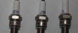
— Candles: carbon deposits may appear on the inner surface, as well as heavy contamination on the outside. Violation of the gap between the electrodes, various cracks in the insulator, malfunction of the side electrode - all this leads to poor spark supply or its absence at all.
- the surface of the thread is dry (in no case wet);
— there is a very thin layer of soot or soot;
— the color of the electrodes, as well as the insulator, should be from light brown to light gray, almost white.
The wet surface of the thread can tell about all the malfunctions - it can be either gasoline or oil. In a faulty spark plug, the electrodes and part of the insulator are covered with a thick layer of soot and are wet.
If the engine has a very high mileage, and all the spark plugs were replaced at the same time, then the main reason for this condition is increased wear of the cylinders, rings or pistons. Oil may appear on the surface of the spark plug during the period when the car is being run-in.
This goes away over time. If oil was found on only one spark plug, then the cause of this most likely may be a malfunction of the exhaust valve; it may burn out. To determine this, you need to listen carefully to the engine; at idle it runs unevenly. In this case, you cannot delay repair work, as the seat will then burn out, and repairs will be even more expensive.
Burnt out or very badly corroded electrodes only indicate overheating of the spark plug. This is possible if low-octane gasoline was used, or the ignition timing was incorrectly set. A mixture that is too lean is also the result of melted electrodes.
Various mechanical damage to the surface of the spark plug is possible. It may have a bent appearance, or the electrode located on the side of the spark plug will be deformed. The consequences of such work are interruptions in ignition. The cause of such troubles may be the incorrectly selected length of the spark plug, or the length of the thread does not correspond to the seat in the motor head.
After the spark plugs have been swapped, you can find out a very large amount of information about their condition. If the spark plug continues to become covered with soot in another cylinder, this indicates its malfunction. But if a normal and serviceable spark plug of one of the neighboring cylinders also begins to become covered with soot, like its predecessor, then this is a malfunction directly in the crank device of this cylinder.
Malfunctions of the ignition system can lead to failure of other devices used for the normal operation of the machine. There is a separate list of common malfunctions that make it difficult to operate the working mixture ignition system: - The primary winding of the ignition coil can short-circuit to ground, as well as the secondary winding short-circuit to the primary.
As a result, the additional resistor burns out and characteristic cracks appear in the insulator, as well as in the coil cover. In this case, it is necessary to replace the damaged elements, but if the coil is almost destroyed, then replace the entire assembly.
— Typical faults of the breaker: possible burning or oil contamination of the contacts inside the breaker; violation of the standard gap between the contacts, which leads to interruptions in switching between spark plugs. Burning or oiling of the contacts can cause a very sharp increase in the level of resistance between them, because of this, the current created in the primary winding decreases, and as a result, the power of the spark created by the spark plugs decreases.
Violation of the gap also leads to a deterioration in the formation of the spark that is created between the electrodes of the spark plug. The result is interruptions in the normal operation of the engine. — Candles: carbon deposits may appear on the inner surface, as well as heavy contamination on the outside.
Violation of the gap between the electrodes, various cracks in the insulator, malfunction of the side electrode - all this leads to poor spark supply or its absence at all. This causes unstable, uneven and unstable operation of the motor, reducing its power. It is also possible to stop when the load increases.
Normal operation of spark plugs is possible only if: - the thread surface is dry (in no case wet); — there is a very thin layer of soot or soot; — the color of the electrodes, as well as the insulator, should be from light brown to light gray, almost white.
If the engine has a very high mileage, and all the spark plugs were replaced at the same time, then the main reason for this condition is increased wear of the cylinders, rings or pistons. Oil may appear on the surface of the spark plug during the period when the car is being run-in.
This goes away over time. If oil was found on only one spark plug, then the cause of this most likely may be a malfunction of the exhaust valve; it may burn out. To determine this, you need to listen carefully to the engine; at idle it runs unevenly.
In this case, you cannot delay repair work, as the seat will then burn out, and repairs will be even more expensive. Burnt out or very badly corroded electrodes only indicate overheating of the spark plug. This is possible if low-octane gasoline was used, or the ignition timing was incorrectly set.
A mixture that is too lean is also the result of melted electrodes. Various mechanical damage to the surface of the spark plug is possible. It may have a bent appearance, or the electrode located on the side of the spark plug will be deformed. The consequences of such work are interruptions in ignition.
The cause of such troubles may be the incorrectly selected length of the spark plug, or the length of the thread does not correspond to the seat in the motor head. In this case, you should choose a standard spark plug recommended by the manufacturer.
DETAILS: How to change rear brake pads on a Chevrolet Cruze: video
If its length was chosen correctly, you should pay attention to the presence of foreign mechanical elements in the inside of the cylinder. After the spark plugs have been swapped, you can find out a very large amount of information about their condition.
If the spark plug continues to become covered with soot in another cylinder, this indicates its malfunction. But if a normal and serviceable spark plug of one of the neighboring cylinders also begins to become covered with soot, like its predecessor, then this is a malfunction directly in the crank device of this cylinder.
Spark plug
No ignition system can work without the main element - the spark plug. This part is capable of converting pulses received from high voltage into a special spark charge to ignite fuel vapor in the combustion chamber. For a spark plug to work well, the temperature level of its lower insulator should be around 500-600 degrees.
It is worth noting that at a temperature of 500 degrees, carbon deposits may occur on the surface of the insulator. The result is interruptions in operation and poor spark transmission. At a temperature of 600 degrees, so-called glow ignition is possible - this is premature ignition of the mixture due to the high temperature of the insulator.
When choosing candles, they are guided by the so-called heat rating, the value of which is initially set by the manufacturer. The higher the heat value, the less the candle is subject to heating; it is also called a colder candle.
Oily spark plugs and other signs of trouble
— Ignition timing and its angle. If necessary, adjustments are made and the standard value for a given vehicle is set.
— Checking voltage circuits. To do this, the high voltage wires are removed and their throughput and breakdown are checked using a special tester.
In order to obtain the most accurate information about the state of the ignition circuits, as well as about all the processes occurring inside, specialized stands equipped with oscilloscopes are used. Thanks to this, you can get the most accurate value and very quickly determine the level of system performance.
All these actions are needed to determine the malfunction of the ignition system. At the initial stage, you can get by with minimal losses, for example, by replacing wires. At the same time, the performance of the engine is maintained, which is very important, since its repair costs much more than replacing one of the elements of the ignition system.
- Troubleshooting the ignition system
- How to set contactless ignition on a VAZ 2101
- Parktronic electronic acoustic system for parking a car Types of operation principle fault detection and repair of APS
- Ignition system malfunctions