Ignition delay period
During this period, a small portion of the fuel injected during the cycle enters the combustion chamber.
During this period, the indicator diagram shows no noticeable changes in the flow of the compression line: the pressure in the cylinder continues to increase as if no fuel were entering it. As Qi increases, a lot of fuel accumulates in the combustion chamber at the time of ignition. This increases the operating rigidity of the diesel engine. The duration of the ignition delay period depends on the following main factors: fuel quality, fuel injection advance angle, pressure and temperature of compressed air at the start of fuel injection, injection start pressure, diesel load and crankshaft speed. Let's consider the influence of each factor on the Qi value.
The chemical composition of diesel fuel greatly influences the Qi duration. The best diesel fuels are paraffin fuels, which have a higher cetane number and provide the shortest Qi duration and smooth diesel operation.
Each diesel design has its own fuel injection advance angle (FVP). Its optimal value depends on the load, thermal conditions, crankshaft speed, pressure and air temperature. As the FVP increases, the fuel injected into the combustion chamber enters a cold environment with low pressure, i.e., a lower volumetric concentration of oxygen. As a result, fuel ignition is delayed. Fuel accumulates in the cylinder, which burns before the piston reaches the top. This causes an increase in the rigidity of diesel operation and pressure Pz. With a low value of the FVP, the fuel does not burn completely, most of it burns during the expansion process (in the third phase), heat transfer into the cylinder walls increases, and the diesel power decreases.
An increase in the pressure and temperature of the compressed air at the start of injection contributes to earlier self-ignition of the fuel, a reduction in the ignition delay period, and smoother engine operation.
An increase in injection start pressure leads to an additional delay in the start of injection and the injection duration is reduced. When the injection start pressure decreases, the quality of fuel atomization and mixture formation deteriorates, which leads to a deterioration in the working process.
An increase in load is accompanied by a greater fuel supply per cycle, and the conditions for preparing the working mixture for combustion are improved. Consequently, the duration of Qi decreases with increasing load.
The crankshaft rotation speed n affects the value of Qi in the following way. When n changes, the FVP, pressure and duration of fuel injection, and the quality of its atomization change. The pressure and temperature of the air in the compression chamber also changes by the time injection begins. On high-speed diesel engines intended for operation with frequently changing speed conditions, devices are installed that ensure automatic change in the value of the FVP when n changes.
From the above it is clear that the moment of injection start and the ignition delay period have a great influence on the combustion process, on the power and efficiency of diesel engines. Therefore, during their operation, these indicators must be maintained within specified limits.
The average rate of pressure rise in section 2...3 determines the severity of the diesel engine. It is considered non-rigid if the average rate of pressure increase delta_P/delta_f does not exceed 0.5 MPa per 1° crankshaft rotation angle.
The more fuel enters the cylinder during the ignition delay period Qi, the harsher the engine operation and the greater the maximum combustion pressure Pz reaches.
The nature of fuel supply is determined by the cam profile, the diameter and stroke of the fuel pump plunger, the design of the diesel engine and the quality of the fuel. For example, the use of gasoline instead of diesel fuel causes the appearance of shock waves and pressure vibration in the diesel cylinder.
What is compression ratio
The movement of the piston occurs as a result of the pressure of gases that are formed during the combustion of the fuel-air mixture. Before ignition, the mixture is compressed by a piston in the cylinder. The remaining volume in the cylinder after complete compression of the fuel (the volume above the piston at TDC) is called the combustion chamber.
The compression ratio is the ratio of the volume of the combustion chamber to the total volume of the cylinder. It is calculated by the formula: ξ = (Vр + Vс) : Vс , where Vр is the working volume, Vс is the volume of the combustion chamber.
Compression ratio
For example, the total volume of the cylinder is 500 cubic centimeters, and the volume of the combustion chamber is 50 cubic centimeters. Compression by 10 times. This means the compression ratio will be 10:1.
The compression ratio is a ratio and a relative value.
Determination of the knock resistance of gasoline
The knock resistance of gasoline is expressed in its octane number.
The octane number of gasoline indicates that this type of fuel has the same knock resistance as the reference comparative mixture of hydrocarbons - isooctane and normal heptane. Since isooctane has an octane number of 100, and normal heptane has an octane number of 0, an octane number of 80 means that the knock resistance of gasoline is equal to the knock resistance of a mixture of 80% (parts by volume) isooctane and 20% (parts by volume) normal heptane. Knock resistance increases with increasing octane number.
The octane rating is determined on an appropriate test bench using a reference engine to evaluate the knock resistance of different fuels. The reference in this case is a single-cylinder, four-stroke benzoin engine with a thermosyphon liquid cooling system, in which there is no pump, and the coolant evaporates and low-pressure steam condenses in the radiator, and then returns to the cooling jacket as condensate. The engine compression ratio during testing can vary between 4 and 18.
There are two standardized testing methods: the exploratory method and the motor method. Accordingly, the results are the research octane number of gasoline (ROZ) and the motor octane number of gasoline (MOZ). The differences in the main parameters of both methods are shown in the table.
Table. Differences in parameters of exploratory and motor methods
In the motor method, the mixture of air and gasoline is heated behind the carburetor, and in the research method, the air is heated in front of the carburetor.
The reference motor is started and connected to a large electrical generator, in which the torque from the reference motor excites an electrical current that produces a braking torque. The octane number is always measured in the strong detonation mode during combustion of the working mixture. In this case, the excess air coefficient is adjusted so as to obtain detonation of maximum intensity. An inductive sensor and an electronic signal amplifier measure the level of detonation and display the readings on the display of a special device - a detonometer. The engine compression is adjusted so that the detonometer readings of the gasoline being tested are in the middle of the instrument scale. Then two comparative mixtures are introduced into the power system, whose octane numbers differ by only two units. One comparison mixture should cause stronger and the other weaker detonation than gasoline. Using linear interpolation, the octane number of gasoline is determined and rounded to tenths.
The same gasoline tested using the motor method has a lower octane number than that detected using the research method. The octane number determined by the motor method in modern gasoline is approximately 10 units less than the octane number determined by the research method. This difference is due to the fact that the ratio of olefins and aromatic hydrocarbons in the two test methods is different. Today, the research octane number in gasoline is approximately 92, and in premium gasoline it is 95 units. The octane number, determined by the research method, indicates how the fuel behaves during acceleration (detonation during acceleration).
The octane number determined by the motor method, on the contrary, indicates behavior under heavy load (detonation at high crankshaft speed).
Along with research and motor octane numbers, there is also a road octane number (SOZ). It is determined by road testing the vehicle according to the “modified road method”. Various comparative mixtures of isooctane and normal heptane are fed into the warmed-up engine. The car first accelerates to maximum speed in direct gear, allowing smooth movement without jerking. The ignition timing is adjusted until detonation disappears. As a result, the test data forms the base curve shown in the figure.
Then, using the same method, the ignition setting at which detonation begins is determined for the gasoline under study. The base curve determines the road octane number of gasoline. This value will have different values for the same gasoline in different engines.
Volume - chamber - combustion
The volume of the combustion chamber and the pipelines connecting it to the turbine is small compared to the air flow. Therefore, the influence of the gas volume in front of the turbine on the control process has little effect. The regulation works quite steadily, without pulsations, both during synchronization and during normal operation. With complete load shedding, the overshoot is very small.
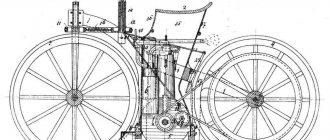
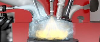
| Diagram of a single cylinder diesel engine. |
The volume of the combustion chamber and the working volume add up to the total volume of the cylinder. The compression ratio shows how many times the total volume of the cylinder is larger than the combustion chamber.
The volume of the combustion chamber is assumed to be filled with residual gases. The numerical values of the quantities included in equation (21.9), with the exception of R0, depend on the operating conditions of the engine and have a significant impact on the value of the weight charge.
The sum of the volume of the combustion chamber and the working volume of the cylinder is called the total volume of the cylinder.
In the volume of the combustion chamber (volumetric mixture formation), when fuel is injected directly into the moving air environment, and it is not expected to hit the surfaces limiting the combustion chamber. In this case, the fuel can ignite in several zones where temperatures are highest and the composition of the mixture is within the concentration limits at which ignition of the fuel is possible.
To change the volume of the combustion chamber, when operating on different types of fuel, a special small piston is installed in the upper part of the engine cylinder head.
| Permissible loads on dowels driven into walls. |
As the distance increases, the volume of the combustion chamber increases, the gas pressure decreases and the depth of the dowel decreases.
| Diagram of a Ford engine cylinder with stratified fuel supply. |
The surface-to-volume ratio of the combustion chamber can be lowered by increasing the cylinder displacement, by increasing the stroke-to-bore ratio, by reducing the compression ratio, and by changing the shape of the combustion chamber.
These thermal stresses of the volume of combustion chambers were established for certain units (steam boilers) equipped with burners that differed little in the torch that they created.
The surface to volume ratio of the combustion chamber is of great importance. If the unburned charge is compressed in a small space, then the walls of the chamber sufficiently cool the gas and affect the course of chemical reactions. A large surface area increases the likelihood of circuit breakage, not so much due to diffusion (since the pressure is too high), but rather due to the transfer of active particles by the moving gas, which causes an increase in ignition delay.
| Piston stroke and cylinder volumes. |
The cylinder displacement and combustion chamber volume taken together constitute the total volume of the cylinder. In multi-cylinder engines, the sum of the displacements of all cylinders is expressed in liters and is called the engine displacement. For small volumes - up to one liter - it is expressed in cubic centimeters.
Engine capacity
Before talking about compression and compression ratio, let's understand the concept of volume. A cylinder has 3 types of volumes:
The total volume includes the working volume and the volume of the combustion chamber. Each engine has a certain number of cylinders. To find out the total engine volume, you need to add up the parameters of each cylinder.
Engine cylinder volumes
To calculate the working volume of one cylinder, you need to multiply the cross-sectional area of the cylinder by the length of the piston stroke. The piston stroke length is determined by the distance from bottom dead center (BDC) to top dead center (TDC), i.e. from the maximum lower to the maximum upper position of the piston.
According to the formula it looks like this: Vwork. = πr 2 h , where π = 3.14, r is the radius, h is the length of the piston stroke.
For example, if the volume of one cylinder is 499 cubic centimeters, and there are four cylinders, then you need to multiply 499 by 4 and we get 1996 cubic centimeters. Next, round to 2000 and divide by 1000 to get the value in liters. Thus, the engine displacement will be 2 liters.
Engine volume is a parameter of the internal combustion engine that determines its power.
In most countries, the cost of car tax depends on the engine displacement. The higher it is, the more expensive the tax is. For example, the engine volume of the Japanese Kei Car is only 0.66 cubic centimeters. Owners of these cars do not pay road tax at all.
The displacement of any engine is measured in cubic centimeters or liters. Based on volume, cars are divided into categories:
- minicar (no more than 1.1 liters);
- small-capacity (from 1.2 to 1.7 liters);
- mid-displacement (from 1.8 to 3.5 liters);
- large-capacity (from 3.6 and more).
The larger the volume, the more fuel-air mixture is placed in each combustion chamber. This indicator directly affects fuel consumption, but at the same time the car’s power increases.
Requirements for the combustion chamber of a gas turbine engine
The combustion chamber is one of the most complex elements of an engine design. Currently, it must satisfy the following ten requirements:
A high value of the combustion efficiency coefficient η, equal to the ratio of the energy released when burning 1 kg of fuel to the calorific value of the fuel. Typical values of η are 0.98..0.99. Small total pressure loss δ=p1∗−p2∗p1∗⋅100%{\displaystyle \delta ={\frac {p_{1}^{*}-p_{2}^{*}}{p_{1}^ {*}}}\cdot 100\%}, as this leads to a decrease in thrust. Typical δ values: 3% (counterflow chambers), 6% (uniflow engines), 8% (double-circuit engines). Small camera dimensions for lighter weight
In this case, the length of the chamber is usually 2-3 times greater than the height. Ensuring a wide range of parameters (air consumption, fuel) - providing the ability to work in different modes: 2≤α=GairLGfuel≤50{\displaystyle 2\leq \alpha ={\frac {G_{air}}{L_{0}G_ {fuel}}}\leq 50}, where L is the stoichiometric coefficient (the amount of air required to burn 1 kg of fuel is taken to be ≈0.1488). Ensuring a given diagram of the temperature distribution in the outlet section of the chamber with minimal unevenness of this temperature in the circumferential direction (if the degree of unevenness is large, the nozzle apparatus may burn out). Reliable camera launch at temperatures down to −60 °C, including flight launch at an altitude of 7 km. Low exhaust smoke (for visual inconspicuousness). The concentration of toxic substances in the exhaust gases at the nozzle exit should not exceed ICAO standards - a more important requirement. The most significant concentrations of substances are CO, CnHm, NOx. No vibration combustion (self-oscillations). A certain service life (minimum 4000 hours before repair, 20,000 hours in total is about 2 years).
Continuous combustion chamber
Continuous combustion chambers are among the most important components of aviation and space propulsion systems, special and transport gas turbine units, which are widely used in the energy sector, chemical industry, and railways. transport, sea and river vessels.
Continuous combustion chamber 1 - Rear compressor housing 2 - Injector 3 - Chamber casing 4 - Power pipe 5 - Flame pipe 6 - Gas collector 7 - Manifold 8 - Nozzle apparatus of the first stage of the turbine
Principle of operation
The combustion chamber is a component of a gas turbine engine (GTE) in which the air-fuel mixture is prepared and burned. To prepare the air-fuel mixture, fuel is supplied to the combustion chamber through nozzles and air is supplied from the compressor. When starting the engine, the air-fuel mixture is ignited by an electric spark (or starting device), and during further operation the combustion process is maintained continuously due to the contact of the resulting air-fuel mixture with hot combustion products. The gas formed in the combustion chamber is directed to the compressor turbine.
The stability and perfection of processes in the combustion chamber largely ensure the reliable and economical operation of a gas turbine engine.
Requirements for a continuous combustion chamber
- Stability of the combustion process under all possible modes and flight conditions. It is necessary that the combustion of fuel is continuous and that there is no flameout or pulsating combustion, which can cause the engine to shut down. As the engine operating mode and flight conditions change, the ratio of fuel and air entering the combustion chamber changes, i.e. the quality of the mixture changes.
- Ensuring a uniform gas temperature field in front of the turbine. Combustion chambers typically have multiple injectors to supply fuel, so there is a tendency to have zones of varying temperatures as the gases exit the combustion chamber. Significant unevenness of the gas temperature field can lead to the destruction of turbine blades.
- Minimum flame length, i.e. The combustion process must end within the combustion chamber. Otherwise, the flame reaches the blades of the nozzle apparatus, which can lead to their burnout.
- Reliable operation, long service life, ease of control and maintenance. Ensuring long-term and reliable operation of the combustion chamber is achieved both by a number of design measures and by strict adherence to the rules of flight and technical operation. To ensure maximum fulfillment of the listed requirements, the appropriate type of combustion chamber is selected for each type of engine.
Design and types of combustion chambers
The geometric dimensions of the engine chambers are set from the condition of ensuring a given thrust at the highest possible specific thrust values, i.e. with the greatest possible use of the energy contained in the fuel.
The volume of the chamber is determined by the residence time of fuel and gaseous products in the chamber - τpr.
. it must be sufficient to complete the process in the combustion chamber.
The volume of the combustion chamber is determined by the formula
where is the weight per second gas consumption;
R – gas constant of combustion products;
To and Po are the temperature and pressure of the gases in the chamber.
Another parameter used to determine the volume is the reduced length - Lpr.
— , where
Fcr
is the critical section area of the nozzle.
To final determine the dimensions of the chamber, it is necessary in addition to Vk
know the chamber diameter
do
or dimensionless area
fk
=
Fo/Fcr
.
Usually fk
≥ 3 is taken. Approximately the chamber diameter for nitric acid engines is determined by the dependence
do = (2.5...3)dcr
, and for alcohol-oxygen engines
do = (2.5...2.5)dcr
.
The shape of the combustion chamber can be spherical (pear-shaped, for example, on the V-2 engine), cylindrical (on the engines of modern launch vehicles) and conical (practically not used).
The advantages of a spherical combustion chamber are that
1. for a given volume, its surface is the smallest, which reduces the weight of the combustion chamber and facilitates cooling;
2. These combustion chambers are more durable compared to cylindrical combustion chambers.
The disadvantages of a spherical combustion chamber are that
1. it is difficult to manufacture;
2. has a small area for placing nozzles and therefore the nozzles are placed in pre-chambers, which complicates the combustion chamber manufacturing technology.
Cylindrical combustion chambers are convenient and easy to manufacture. The process of mixture formation is easily carried out in them. The disadvantages of the combustion chamber are that the strength properties are lower than those of a spherical chamber and there is a larger surface for cooling.
The conical combustion chamber is the inlet part of the nozzle and is therefore easy to manufacture. The main disadvantage of the chamber is the low specific thrust, since due to the acceleration of combustion products along the length of the chamber and the pressure drop, the combustion process is not completed.
The preparation of fuel and oxidizer for combustion is carried out in the process of mixture formation: fuel components are atomized
,
mix and partially evaporate
.
For better mixture formation, it is necessary to ensure:
1. fine atomization of the components and their good mixing (characterized by the diameter of the droplets - 25...250 microns);
2. uniformity of fuel concentration across the cross section of the chamber (losses due to physical incomplete combustion are reduced);
3. uniform speeds of movement across the cross section of the combustion chamber, because at high speeds the combustion is incomplete, and at low speeds the chamber volume is not fully used.
These conditions can be met by selecting the appropriate camera head, the type of nozzles and their location on the head.
Liquid rocket engines use flat heads, spherical heads with prechambers, and tent heads .
Flat heads (Fig. 10) are used for cylindrical or conical combustion chambers. They have a simple design and, in combination with cylindrical chambers, ensure uniformity of the velocity field and fuel concentration across the cross section. Their disadvantage is low strength and rigidity. Nozzles are placed on flat heads in 3 ways: staggered arrangement; concentric and cellular. The honeycomb arrangement provides a better mixture formation process, since there are 6 oxidizer nozzles per fuel injector. It is possible to combine a concentric nozzle arrangement with a checkerboard and honeycomb arrangement.
Spherical heads with prechambers are used for pear-shaped or spherical combustion chambers (“V-2”, 8K52), i.e. for high thrust engines. Their nozzles are located in the antechambers: in the center there is an “O” nozzle with a large number of holes located at different angles to the axis of the antechamber, and the “G” nozzles are placed on the side surface of the antechamber.
Tent heads are difficult to manufacture, and it is difficult to organize good mixture formation in them.
The quality of the spray depends on the type of nozzles and their design. According to the principle of operation, nozzles are divided into two groups:
1. jet nozzles (slit type);
2. centrifugal nozzles - tangential and screw (with swirlers).
Nozzles can be single-component or two-component.
Jet nozzles Fig. 11 are the easiest to manufacture. The main disadvantages of jet nozzles are coarse fuel atomization, small spray cone angle (≈10...15o) and long jet range, which increases the spray area and lengthens the combustion chamber.
In centrifugal nozzles, an artificial swirl of the component is created. In a tangential nozzle, liquid enters through a hole whose axis is perpendicular to the axis of the nozzle, but does not intersect with it. The central part of such a nozzle is not filled with liquid - there is a gas vortex in it, and the liquid is located along the periphery.
In a screw nozzle, twisting is carried out by a screw having screw channels on its surface.
Centrifugal nozzles provide a large spray angle (≈70...120°) with a short spray jet length.
Two-component nozzles improve mixture formation, as they provide mixing of components in the liquid phase, but they are difficult to manufacture and are used when there is not enough space for placement.
5. Geometric dimensions and shape of the nozzle.
The combustion products formed in the engine chamber enter the nozzle, where thermal energy is converted into kinetic energy of gas movement.
The state of combustion products, like any gas, is characterized by well-defined physical quantities (parameters), the main of which are:
absolute pressure P
, absolute temperature
T
, density
ρ
(specific gravity
γ
or specific volume
υ )
, gas constant
R
and exhaust velocity
W.
For ideal gases or their mixtures, a connection has been established between the main parameters in the form of an equation of state: (1)
The process in the engine chamber occurs without heat being supplied to the gas or removed from the gas. This process is called adiabatic.
For an adiabatic process, there is a connection between the parameters, expressed by the dependencies:
, . (2)
Gas from the chamber enters the nozzle. From the energy equation it is established that the relationship between gas velocity and channel cross-section is expressed by the equation , (3)
where M=W/a
(
a
is the speed of sound).
The properties of the gas flow depend on the speed of sound. In an adiabatic process, the speed of sound is determined by the formula. The section where the gas speed is equal to the speed of sound is called critical
and all flow parameters are also called
critical
.
Equality of the two speeds can be obtained only at a certain ratio of pressure in the chamber and at the nozzle exit: . This ratio is the initial parameter when designing a nozzle and is related to the Sa/Scr ratio, which is called nozzle broadening
.
Supersonic velocities of combustion products can be obtained using a Laval nozzle (supersonic nozzle), which is a channel whose cross-section first decreases and then increases (see nozzle formula - equation (3))
As follows from formulas (1,2,3), the parameters of the gas flow along the length of the nozzle change as follows (Fig. 14).
The dimensions and shape of the nozzle are chosen so that the nozzle does not produce large energy losses. Its surface should be the smallest, since as the surface increases, the weight of the nozzle and the amount of heat given off to the coolant increase. It is impossible to avoid energy losses when gas moves through the nozzle, but they can be reduced.
One of the losses is friction losses. They depend on the shape of the nozzle inlet. To reduce these losses, the entrance to the nozzle is made smooth, and in the critical section the nozzle is rounded (the rounding radius is usually taken to be r = dcr
).
In the exit part of the nozzle, energy losses are possible due to flow separation from the wall and due to gas friction on the surface. When Fa=const and Fcr=const, the nozzle surface can be reduced by decreasing its length or increasing the opening angle of the outlet cone. However, an increase in the opening angle of the outlet cone is possible up to a certain critical value at which flow separation can occur. There is an optimal opening angle value - 2α ≈ 20°...30°
.
In addition to the listed losses in conical nozzles, there are losses due to speed dissipation: the gas speed at the nozzle exit is directed at an angle to the axis and therefore only the axial component of the speed participates in the creation of thrust. The larger the nozzle opening angle, the greater the dissipation losses, and decreasing the angle lengthens the nozzle, i.e. increases friction losses. They reduce dispersion losses by profiling the nozzle, which can be gas-dynamic (ideal) and optimal. During gas-dynamic profiling, the shape of the outlet part is selected so that the gases flow out in a beam parallel to the nozzle axis. This is achieved by smoothly decreasing the nozzle opening angle along the length so that at the inlet it is equal to zero or very small. The length of an ideally profiled nozzle increases by 1.5 times compared to a conical nozzle, but the specific thrust increases by 4.5%.
In practice, optimal nozzles have been used that provide the greatest engine thrust under certain conditions - length, weight, Fa/Fcr. In this case, the exit part of the nozzle is made with opening angles 2α1
and
2α2
, and the transition line between them is constructed along a parabola, see Fig. 15.
Since the temperature in the gas flow is very high, huge heat flows are transferred from the gas to the walls of the chamber and nozzle. To protect the walls, external, internal and mixed
cooling are used.
When external
During cooling (Fig. 16), the coolant enters the manifold, and from it into
the undershirt
space. The coolant is a component that can absorb more heat, i.e. having a large heat capacity and a high boiling point.
With internal
During cooling, a wall layer with a lower temperature is created, which reduces heat flows to the chamber wall. For example, fuel can be supplied through special annular belts with jet or slot nozzles. The liquid, under the influence of the gas flow, spreads in a thin layer over the surface and evaporates. As a result, two protective layers appear: liquid and vapor curtains.
A type of internal cooling is porous
cooling: liquid enters the chamber through the pores, creating a vapor curtain.
The disadvantage of internal cooling is a decrease in the specific impulse of the engine due to incomplete participation of fuel in the combustion process.
Mixed
cooling is a combination of two types of cooling.
Depending on the ratio of the pressure at the nozzle exit Pa and the pressure in the environment Ph, the nozzle can operate in the design mode (Pa = Ph), overexpansion mode (Pa < Ph) and underexpansion (Pa > Ph) Fig.
17. Since thrust is the axial resultant of the forces of external and internal pressure distributed over the inner surface of the chamber and the outer surface of the rocket, it is clear from Figure 17 that deviation from the design mode leads to a decrease in thrust and specific impulse of the engine. In the case of underexpansion (Fig. 17, A), the pressure in the jet will be equal to Рh
Only in section 1-1 and in the area from the nozzle exit to 1-1 the jet energy is lost. Therefore, the specific impulse of the engine in this case will be lower than in the design mode.
In the overexpansion mode from section 2-2 to the nozzle exit, the axial resultant force will be directed against the thrust force.
Thus, it becomes obvious that the optimal operating mode of the nozzle at a constant fuel consumption is the design mode. In design mode, the engine will have a maximum specific impulse.
Underexpansion of pressure in the gas flow occurs when the rocket rises to altitude. The gas flowing from the nozzle at excess pressure expands in the atmosphere and mixes with the external environment. In this case, the flow velocity during expansion outside the nozzle practically does not increase due to the formation of vortices at the boundaries of the jet.
During overexpansion (overexpansion can occur, for example, when fuel consumption in the engine decreases and the pressure in the combustion chamber decreases accordingly), the flow decelerates outside the nozzle and the speed decreases to subsonic. The transition to subsonic speed is accompanied by an abrupt increase in pressure. As the external pressure increases, the pressure surges approach the nozzle exit and, at a sufficiently large excess pressure in the atmosphere (according to some data Рh/Pa > 2.5...5.5) enter the nozzle.
In this case, the normal operation of the nozzle is disrupted, since the formation of shocks inside the nozzle leads to separation of the flow from the walls, the emergence of powerful vortices and large losses of kinetic energy.
Factors influencing the duration of the first combustion phase
- The flammability of the fuel, which is assessed by the cetane number. The higher the cetane number, the better the flammability.
- Pressure and temperature of the air charge at the beginning of fuel injection. As pressure and temperature increase, the ignition delay period shortens.
- The type of combustion chamber, which affects the ignition delay, since depending on the type of chamber, fuel will spread differently throughout the volume of the air charge and in the near-wall zone. In addition, the temperature of the walls of the combustion chamber will also depend on its type.
- The intensity of the directional movement of the charge in the chamber. Increasing the intensity of charge movement slightly shortens the ignition delay period. The figure shows ways to create a vortex motion of a charge in the cylinder during intake.
- Nozzle type. The closed type nozzle reduces the ignition delay period. Divided combustion chambers have a main and auxiliary cavities connected by a neck. Currently, vortex combustion chambers and prechambers are mainly used, where the axis of the connecting neck is directed tangentially to the inner surface of the combustion chamber. Split combustion chambers provide more complete fuel combustion and less harsh operation by reducing ignition delay time.
- Load. As the load increases, the pressure and temperature of the cycle increases, which leads to an increase in the thermal regime of the engine, and this in turn causes a reduction in the ignition delay time.
- Crankshaft rotation speed. Increasing the crankshaft speed leads to improved atomization, an increase in pressure and temperature at the end of compression, which helps to reduce the first phase of combustion, especially in diesel engines with divided combustion chambers. The duration of the first combustion phase increases.
The second phase of combustion (02) - self-ignition and rapid combustion begins from the moment of ignition (see Fig. point 2) and ends when the maximum pressure in the cylinder is reached (point 3). First of all, homogeneous layers of a mixture of fuel and air, well mixed with each other, burn. In this case, the flame spreads very quickly, and the pressure increases accordingly, in certain cases with the formation of a shock wave propagating at the speed of sound. But unlike carburetor engines in diesel engines, these waves do not turn into detonation, since the structure of the mixture throughout the entire volume of the combustion chamber is uneven. This allows for a higher compression ratio.
After the air-fuel mixture, well prepared for ignition, burns, combustion continues in areas where the structure of the mixture is more uneven. Here in the indicator diagram there is a slight decrease in pressure growth.
During the second phase, 30-45% of all heat is released. The temperature of the working fluid increases to 1600-1800 K. The maximum pressure can reach 6-9 MPa, and when pressurized, exceed 10 MPa. The duration of the second phase is 0.8-1.5 ms, which corresponds to 10-20° of crankshaft rotation.
Types of combustion chambers of diesel engines
The vast majority of naturally aspirated diesel engines differ only in the design of the combustion chamber. Classic diesel engines use an undivided combustion chamber - fuel is supplied to the space above the piston. Until recently, this type of combustion chamber was used mainly on low-speed, large-volume engines for trucks, since these diesel engines are characterized by high levels of noise and vibration. However, in our time, with the advent of electronically controlled high-pressure fuel pumps (HPF), two-stage fuel injection and stabilization of the combustion process of the fuel-air mixture, these problems on automobile diesel engines have practically been eliminated.
The most common in passenger cars today are diesel engines with a separate combustion chamber - swirl chamber and prechamber. In them, fuel is injected not directly into the cylinder, but into an additional chamber connected to it in the cylinder head. The vortex chamber is connected to the cylinder by one channel in such a way that when air enters it, it swirls intensively. This improves the process of mixture formation and self-ignition. In this case, the fuel-air mixture ignites in two stages - the process begins in the vortex chamber and goes into the combustion chamber. Thus, the pressure in the cylinder increases more smoothly, which results in reduced noise and increased maximum speed. Vortex chamber engines currently make up about 90% of power units of this type in passenger cars and SUVs. More complex, and therefore less common, are prechamber diesel engines. The combustion of the fuel-air mixture occurs in a special insert pre-chamber connected to the cylinder by several channels of small cross-section. Their shape and diameter are selected so that a pressure difference occurs between the cylinder and the prechamber, increasing the gas flow rate. This technology allows for a long service life, additional reduction in noise and toxicity levels, as well as the smoothest torque dynamics.