Installation of UAZ distributor avto-mechanik.ru
Procedure for working with incoming documents
If you have a need to change the distributor on a UAZ car, you can do this as follows. It is necessary to know the ignition order, the direction of rotation of the slider and the position of the coupling between the drive and the distributor itself.
In order to remove the distributor, you need to disconnect the wire and unscrew the adjustment plate fixing bolt, and also remove the high-voltage wires. When installing a new distributor, you need to pay attention to the coupling; it has two protrusions that are offset from the center. The distributor drive has grooves. into which the protrusions of the coupling fit, they are also offset from the center
into which the protrusions of the coupling fit, they are also offset from the center.
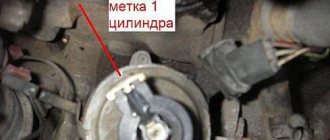
Having inserted the distributor into the drive, you need to rotate the distributor shaft until the protrusions fall into the grooves, and the distributor takes the only correct position. During operation, the mating parts wear out, the protrusions become thinner, and the grooves expand; as a result, the distributor may be installed in the reverse position, so before installation, orient the position of the protrusions relative to the grooves. We install the distributor according to what was said above. Tighten the bolt on the adjusting plate. If the bolt is in the center of the scale, then the distributor must be turned counterclockwise by 2-3 scale divisions to set the ignition timing. Tighten the bolt. We fasten the wire coming from the switch. We install high-voltage wires. There is a number 1 on the cover of the distributor near the connecting contact of the high-voltage wire.
It indicates that the wire coming from this contact is connected to the spark plug of the first cylinder. If you look at the distributor cover from above, then the wire corresponding to the spark plug of the second cylinder must be installed in the next contact counterclockwise. The next counterclockwise will be the contact for the fourth cylinder spark plug and the remaining contact for the third cylinder. That is, the firing order will be 1-2-4-3.
Replacing the timing chain
The scheme for disassembling the engine, installing timing marks and reassembling is in many ways similar to the dismantling and installation of the injection internal combustion engine of the ZMZ 406 modification. The latest engines are installed on the UAZ Patriot and Gazelle.
We very often receive questions from inexperienced car owners or those who are just starting this type of journey: “Why does the timing device and chain break so often.” Let's try to answer it.
Why does the timing chain fail?
Operation under difficult conditions, untimely change of lubricant on the 409 engine, overheating of the engine leads to the fact that the parts of the power unit quickly wear out. Filling with low-quality fuel and replacing it with counterfeit engine oil also affects wear.
It happens that manufacturer’s shortcomings cause a major overhaul of the 409 engine. But this rarely happens.
How to determine the need
The chain needs to be replaced when you notice:
Now let's move on to the replacement process.
Replacement process
In order to correctly replace the timing chain of a UAZ Patriot engine, you need to prepare the necessary tools for this matter:
In addition to the tools described above, you will need a jack and a container for draining the coolant, a protractor for installing timing marks, a star-shaped puller, and a removable nozzle. After the tools are prepared, we proceed to disassembling the engine.
All parts are carefully checked for serviceability; if chips or cracks appear, they are replaced. The rest are washed in kerosene.
After the procedure of removing and testing the functionality of the timing belt elements, its assembly begins. Attention is paid to setting the timing marks, and the crankshaft pin should fit tightly into the socket. Otherwise, it will break the part while the ZMZ 409 engine is running.
Characteristics of the UAZ 469 transmission, chassis and control systems
Transmission
What is the order of operation of the VAZ-2109 cylinders
? The UAZ 469 is equipped with a 4-speed manual transmission with synchronizers in 3rd and 4th gears. The weight of the gearbox without lubrication is 33.5 kg. Oil volume – 1 l.
Gear ratios: First gear – 4.12 Second gear – 2.64 Third gear – 1.58 Fourth gear – 1.00 Rear gear – 5.22
Transfer case
UAZ 469 is equipped with a 2-speed manual transfer case. It is rigidly attached to the gearbox without an intermediate driveshaft. Its weight including the handbrake is 37.4 kg. The volume of oil to be filled is 0.7 l.
Gear ratios: Direct transmission – 1.00 Low gear – 1.94 Power take-off – up to 40%
UAZ 469B has a single-speed transfer case.
Ignition of UAZ-469
Contents of the material
Engine cylinder operation table
Rice. 108. Diagram of the UAZ-469 ignition system: 1 - battery; 2 — “mass” switch; 3 - voltage regulator; 4 - generator; 5 - ammeter; 6 — ignition switch UAZ-469; 7 — ignition breaker contacts; 8 — ignition distributor; 9 - capacitor; 10 — ignition distributor cover; 11 — slider; 12 — spark plug; 13 - high voltage wire; 14 - additional resistance; 13 — additional starter relay; 16 - ignition coil: 17 - starter. A more conventional designation for the colors of the UAZ-469 ignition wires: G - blue; K - red; O - orange; F - purple; H - black.
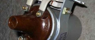
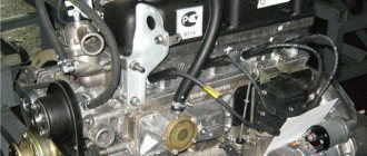
The coil is sealed with a carbonite cover in a casing with a rubber gasket. The casing is filled with transformer oil, which improves winding insulation and heat dissipation. To avoid damage to the coil, do not leave the UAZ-469 ignition on when the engine is not running. The distributor (Fig. 110) is designed to distribute high voltage pulses across the engine cylinders in the required sequence. It is installed on the left side of the engine block and is driven by the engine oil pump shaft. The distributor shaft rotates counterclockwise (as viewed from the side of its cover).
Rice. 109. Ignition coil UAZ-469:1 - cover; 2 - contact socket; 3 - screw; 4 - low voltage terminal; 5 - sealing gasket; 6 - ring magnetic circuit; 7 - primary winding; 8 - secondary winding; 9 - porcelain insulator; 10 — coil casing; 11 - transformer oil; 12 - core; 13 — electrical cardboard; 14 - additional resistor; 15 - ceramic holder; 16 — contact spring.
The distributor has two devices: a low voltage current breaker in the ignition coil circuit and a high voltage current distributor. To automatically change the ignition timing, there are centrifugal and vacuum regulators.
Rice. 110. Ignition distributor: 1 - vacuum regulator; 2 - fixed plate of the breaker; 3 - cover; 4 — rotor; 5 - felt; b - coal; 7 - cam; 8 — grease nipple; 9 — octane corrector plate; 10 — distributor fastening bolt; 11 - coupling; 12 — spring pin holder; 13 — bushing; 14 — body; 15 - weight; 16 — bearing; 17 - movable breaker plate.
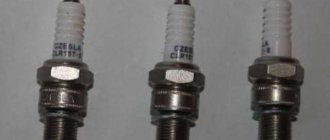
Rice. 111. Measuring the gap between the spark plug electrodes:
a - gap.
To ensure reliable operation of the ignition system, adjust the gap between the breaker contacts. Before adjusting the gap, inspect the working surfaces of the contacts and, if they are dirty, oily or burnt, clean them.
How to set it correctly?
After connection, how is the ignition installed for proper engine operation?
What is the procedure and how to correctly set the node settings, read below:
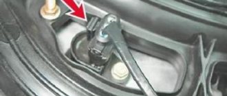
To begin, the vehicle must be secured in place, and turn on the handbrake. The piston of the first cylinder must be installed at top dead center; note that the hole on the crankshaft pulley must coincide with the mark located on the timing gear cover. The cover must be removed from the switchgear. Having done this, you will see a slider located opposite input 1, inside the cover. If it is not there, then the crankshaft must be turned 180 degrees and the octane corrector set to 0. Using a wrench, screw the pointer to the distributor controller body so that it is aligned with the middle mark on the octane corrector
Loosen the screw securing the plastic to the distribution controller housing a little. Carefully turn the housing, holding the slider with your finger so that it does not rotate. This way you can eliminate gaps in the drive
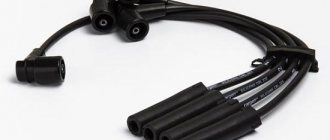
The housing is rotated until the sharp part of the petal on the stator is aligned with the red mark on the rotor. Secure the plate with a screw to the controller body. The next step will be to install the controller cover in place and diagnose the high-voltage wires. They must be installed in accordance with the order of operation of the cylinders, that is, first, second, fourth, third. When the ignition timing is set, it is necessary to diagnose the correctness while driving. Start the power unit and warm it up for about ten minutes until the temperature is about 80 degrees. Moving on a flat and straight road at a speed of approximately 40 km/h, sharply press the gas pedal. If, when accelerating to 60 km/h, you feel or hear detonation, it should be short-lived, then everything has been done correctly. If the detonation is very strong, then the distribution controller must be turned half or one division counterclockwise. In the complete absence of detonation, the set advance angle should be increased, that is, the controller should be turned clockwise.
How to set timing marks on a 409 UAZ Patriot
The setting of the timing marks itself occurs after the mechanism is assembled. The chain, metal gears and other parts are pre-lubricated with motor lubricant.
First of all, the gear is pressed onto the crankshaft. This is a must. Then turn the crankshaft until the mark on it meets the mark on the cylinder block. The first cylinder should be at top dead center. The crankshaft rotates clockwise. Using the indicator, the correct location of the marks is determined.
Where is the chain located
One timing chain is located at the top of the timing mechanism, the second is at the bottom. This arrangement of the timing chains on the ZMZ 409 allows for optimal operation of the power unit.
If you do not keep the tensioners and dampers clean, this will lead to the chain slipping through the teeth. In addition, after 80,000 kilometers the device tends to stretch.
Signs of breakdown of the gas distribution mechanism
Signs of a breakdown of the gas distribution mechanism are the following symptoms:
If you notice the symptoms described above, you should contact a service center to identify the problem and solve it.
Installing camshafts according to marks
To set the camshafts to the marks, you must do the following:
It is necessary to catch the ideal phase so that the supply of the mixture and its exhaust occur without delays or advances of fuel, air or oil.
Now let's talk about what the ideal phase should be.
Ideal phase
The ideal phase helps to achieve maximum engine power. The operation of the power unit will be elastic both at low and high speeds. Fuel consumption will decrease as a result of correct timing marks. In addition, the ideal phase will increase the service life of the power unit.
General concept
The contact ignition circuit itself is not bad, because humanity has been using it since the advent of the first car. But, of course, it is far from the capabilities of contactless ignition. Therefore, many UAZ owners, in an effort to improve the performance of the power unit, reconfigure it.
General ignition circuit for older UAZ models
And not only UAZs, but also other domestic cars, for example, the wiring of the Moskvich 2141 and a number of other brands and models are subject to alterations.
Effect of modernization
What is important is that the engine compartment and interior electrical wiring of the UAZ 31514 remains virtually unchanged, and the alteration itself is characterized by the installation of new elements under the hood. As a result:
As a result:
- The engine begins to operate stably in all modes;
- Improves cold starting;
- Fuel consumption is normalized;
- The engine power will reach the passport data.
Differences between ignition systems
The main difference between the two systems is the moment of sparking:
- In classic ignition, a slider under the distributor cover is responsible for this when it comes into contact with the output contact on the spark plug wire. In this case, the supply of a high-voltage pulse occurs with an increase. It seems to be lubricated, reducing the spark power at the spark plug electrodes.
- In contactless ignition, the switch generates a charge and releases it almost instantly upon receiving a signal from the Hall sensor. As a result, the candle produces a more powerful spark. Among domestic off-road vehicles, the Niva has a similar contactless ignition system - see the VAZ 21213 wiring diagram.
The electronic switch is often mounted in UAZ vehicles on the partition on the left side
Note! More powerful sparking promotes self-cleaning of the spark plug, because fuel burns intensively, leaving no deposits
Read more: Cost of servicing Opel Astra
How to set the ignition
In order to correctly adjust and set the ignition on a UAZ, you must follow the sequence of actions that are given in the user's repair manual.
Before you begin adjusting the ignition system, you must place the vehicle on an inspection pit or a special platform for repair work and apply the hand brake. The wheel mechanisms of the vehicle must be secured with a stopper or stop. The power unit must be turned off.
After this, you can begin installing the ignition. To do this, it is necessary to fix the piston of the first cylindrical element in the position of the highest dead center. In this case, you need to check that the hole on the crankshaft pulley coincides with the pin on the cover of the timing gear block. It is necessary to slightly lower the mounting bolt located on the plate to the distribution equipment sensor housing.
Then remove the cover from the distributor and rotate the crankshaft 180°. The octane corrector must be in the zero position. Then it is necessary to tighten the pointer to the housing of the distribution mechanism sensor with a bolt so that its position coincides with the octane corrector mark.
How to check the ignition coil
Checking is necessary in the following cases:
- The mechanism does not stall when the ignition is turned off.
- A short circuit has occurred.
- The spark plugs in the ignition system have failed.
- The coil heats up, causing the system to overload.
In order to check the ignition coil, you need to turn off the power unit and open the hood. Then you need to find the coil. To do this, it is recommended to follow the wires that lead from the distribution mechanism in the opposite direction. After this, you need to disconnect 1 high-voltage wire from the spark plug. Before the procedure, you must wait until the engine has completely cooled down. This may take 15-25 minutes.
Then you should dismantle the spark plug using a special nozzle. This must be done carefully and make sure that debris does not get into the hole, because. this will lead to malfunction of the power unit. You need to connect the wire back to the spark plug. To perform this operation, it is recommended to use pliers with insulated handles.
After this, you need to touch the threaded side of the candle to the bare metal. When the ignition is turned on, all elements of the vehicle’s electrical equipment will begin to work, which means that the coil is functioning properly. The driver performing repair work should see a blue spark. If it is not there, then the system is faulty. If an orange spark occurs, it means that insufficient voltage is being supplied. This may be due to poor contact, low current, or defects in the coil body.
Another way to check the ignition coil connection:
- Remove the coil from the car. To do this, you need to disconnect the wires of the distribution equipment, remove the fasteners from the coil body using a wrench.
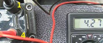
- Determine the condition of the mechanism using an ohmmeter. You need to touch the probes to the primary winding, touching 2 contacts at the same time. After this, it is necessary to measure the condition of the secondary winding and compare the obtained indicators with the factory ones, which are in the repair manual.
Before starting work, it is necessary to place the transport on a flat surface and secure it with special locking devices. When checking the device, it is recommended to wear protective clothing (mask and goggles, as well as gloves).
Review of SZ on famous UAZs
What is the connection diagram for electronic or contactless ignition on a UAZ 417, how to convert contact ignition to contactless? Why does the coil heat up and how to adjust and adjust the advance angle? First, let’s look at the main points regarding the action and types of SZ.
Operating principle of SZ
Contact system diagram
The ignition system, or rather its correct setting, plays a big role in the operation and starting of a car engine. With correct adjustment, the combustible mixture will burn correctly in the power unit as a result of the supply of charge through the spark plugs. A spark plug is placed on each cylinder of the UAZ engine, each of which is turned on in a certain order, in turn, delivering a discharge to the cylinder after a certain time. It must be taken into account that any SZ makes it possible not only to deliver the required discharge, but also determines its strength.
Due to its technical characteristics, the car’s battery cannot produce the voltage and current required to ignite the mixture. This is due to the fact that the battery can only produce a current of a certain strength. And thanks to the correct operation of the system, the current value increases significantly, which allows you to successfully ignite the air-fuel mixture.
The operating principle of the system consists of several stages:
- First, the driver inserts the key into the ignition and turns it, electrical energy is stored in a coil.
- Then the coil converts the low-voltage voltage in the on-board network of 12 volts into high-voltage. As a result, the voltage value increases to 30 thousand V.
- After this, the discharge is distributed and supplied to one or another spark plug.
- The candle itself produces a spark that ignites the mixture.
Diagram of the UAZ contactless system
What types of SZ are there?
Domestic UAZ vehicles can use one of three ignition systems; let’s look at each of them in detail:
- Contact view. This type of SZ is outdated, however, it is used on most machines. In such a system, the principle of operation is to issue a certain impulse that is formed in a distributor - a distribution device. The contact system is considered one of the simplest in terms of design, which is an advantage, since if a malfunction occurs, the car owner will be able to independently check and repair the system. In addition, prices for structural parts of the contact system are usually affordable, which is good news. The contact SZ includes a coil, a switchgear, a breaker, a capacitor and spark plugs.
- Non-contact type, also called transistor type. Compared to the contact system, the contactless system has more advantages. The resulting spark has a higher power, which is achieved due to the formation of high voltage in the secondary winding of the coil. Also, contactless systems are equipped with an electromagnetic device, which makes it possible to achieve more stable operation of the engine. Ultimately, if the UAZ power unit is configured correctly, then by using a contactless system you can not only increase its power, but also achieve fuel savings, albeit insignificant. Also, such systems are easier to maintain. One of the main nuances in terms of maintenance is the need to periodically lubricate the distributor drive - at least every 10 thousand kilometers. One of the main disadvantages is the difficulty of repair. In practice, repairing a contactless SZ will be problematic, since diagnosing the system will require equipment that is usually available at a service station.
- The ignition system can also be electronic. This option is currently considered one of the most progressive and expensive; it is installed mainly on new cars. Compared with contact and non-contact systems, the electronic system has a more complex structure. The main advantage of this system is that, if necessary, the process of adjusting the ignition angle will be much easier. In addition, there are no contacts in the electronic system that are susceptible to oxidation. It should also be noted that in practice, the combustible mixture in the cylinders of a power unit with an electronic system almost always burns completely. But despite all the advantages, electronic repair systems also have their disadvantages, which relate to device repair. It is almost impossible to repair such an SZ with your own hands, since to perform this task, again, you will need equipment (video published by Nail Poroshin).
Specifications
The ZMZ 409 Euro 3 engine has improved technical characteristics compared to its older brother. Thus, the power unit, due to the fact that it was designed on the basis of the 406, received high technical characteristics and endurance.
Let's consider the main technical characteristics of the motor:
In addition to the Euro 3 standard, there are a number of modifications that are worth considering:
- ZMZ 409.10 is the main motor, meets the Euro-2 environmental standard. Power 143 hp
- ZMZ 40904.10 - analogue of 409.10 with a new CPG, new gaskets, DBP, complies with the Euro-3 environmental standard. Power 128 hp Installed on Patriot, Hunter, Pickup, Cargo.
- ZMZ 40905.10 - analogue of 40904.10, compliance with the Euro-4 environmental standard. Power 128 hp Installed on Patriot, Hunter, Pickup, Cargo.
- ZMZ 4091.10 - derated low-end version of ZMZ 40904.10, another receiver, camshafts (lift 8, phase 240), firmware, complies with Euro-3 environmental standard. Used on UAZ loaves. Power 112 hp
- ZMZ 40911.10 is an analogue of ZMZ 4091.10, DBP, meets the Euro-4 environmental standard. Used on UAZ loaves. Power 112 hp
- ZMZ 4092.10 is a non-serial motor. Power 160 hp Used on the Volga.
The procedure for adjusting the valves of UAZ 469
Before adjusting the valves on the UAZ 469, you need to prepare the tools. To carry out the procedure, you will need a screwdriver, wrenches and a set of probes. To make adjustments, you do not need to place the car on an inspection hole or overpass. Work is carried out on a cold engine. Failure to comply with this rule may lead to increased noise and incorrect operation of the engine.
Adjusting valves on the UAZ 469 does not require specialized education. The work can be performed by a person with minimal technical knowledge. Adjustment is carried out in the following order:
- The attachments that prevent the removal of the valve cover are dismantled.
- The valve cover securing nuts are unscrewed. For convenience, you can use a socket wrench.
- The gasket that prevents oil leakage between the cylinder head and the valve cover is removed. When reassembling, it is better to replace the gasket with a new one.
- The piston of the first cylinder is set to top dead center. To determine the correct location of the piston, it is necessary to align the marks located on the crankshaft pulley and the front cover of the power plant. When the piston moves to top dead center, both valves of the gas distribution mechanism will be closed.
- The nut securing the adjusting screw located in the rocker arm above the pusher is unscrewed.
- A feeler gauge is installed between the rocker arm and the valve stem.
- The adjusting screw sets the required gap. The probe should pass between the parts with little effort. Biting the measuring element with timing parts is unacceptable.
- The adjusting screw is secured with a lock nut.
- The crankshaft rotates 180 degrees in the direction of travel.
- Manipulations are carried out on the next cylinder in turn. To adjust each subsequent cylinder, the crankshaft is rotated 180 degrees. The procedure for adjusting the valves on the UAZ 469 is 1-2-4-3.
The power unit is assembled in the reverse order. After adjustment, the engine runs less noisily, dynamic performance increases, and fuel consumption decreases.
Tools for replacing timing chain
Before installing timing marks on the ZMZ-406 , you need to prepare the necessary set of tools:
- Heads and ratchet.
- Socket and open-end wrenches.
- Hexagons.
- Torque wrench.
- Chisel and hammer.
- Pullers with two or three legs.
It is imperative that all threaded connections that are covered with dust, rust, dirt must be treated with penetrating lubricant; this will allow for much faster disassembly of the units.
How to set timing marks 406, 409
Step by step repair. Installation by marks
8:45. Replacement of chains, sprockets, hydraulic tensioners, oil seals, pumps, etc.
Replacing the timing drive ZMZ 409 Euro-3 UAZ Patriot. NEW 2016
Instructions for replacing the timing
on UAZ Patriot
ZMZ 409
. The Ideal kit is installed.
How to properly install and connect xenon to fog lights?
If xenon light sources were installed in the headlights, it is advisable to install them in the PTF. This will prevent you from spoiling the aesthetic appearance of the car.
Installation and Connection Precautions
Nuances that must be observed when installing gas-discharge devices in fog lights:
- If damage appears on the light sources during the task, you must stop working. This also applies to wiring defects, as well as ignition units.
- Before performing the task, the car owner must wash his hands, dry them and degrease them. Otherwise, the bulbs may be damaged and you may receive an electric shock.
- When connected, you should not look at the light sources for a long time without glasses.
- The joints are completely insulated using heat-shrinkable tubing or electrical tape. Otherwise, moisture may get into the wiring, which will lead to a short circuit or fire.
- Before mounting the light source bulbs, it is recommended to degrease them.
Algorithm for installing xenon lamps
In the PTF it is necessary to install devices designed for 4300K or 5000K; this option is more effective in fog and when driving on a wet road:
- Fog lights are usually located under the headlights. Therefore, installing them may require removing the bumper. Sometimes it is enough to unscrew the screws securing the front wheel arches.
- After access to the rear part of the PTF is gained, the optics are disconnected from the power supply circuit. Old light sources are being dismantled and new, gas-discharge ones are being installed.
- High-quality fixation of devices is carried out. They may be subject to vibration while driving, so the bulbs must be securely fastened. Otherwise it will cause them to break.
- Ignition units are installed. The best option would be to place them in the engine compartment or under the front bumper. We need to find free space for installation. It is recommended to choose a protected place where the unit will not be exposed to moisture and aggressive external environments. The devices are secured using clamps or tape. If the package includes special fasteners, then they are used.
Using the Lada Priora as an example, user Sergey M showed the procedure for installing xenon light sources in fog lights.
Instructions for connecting xenon
Gas-discharge lamps in PTF will be connected in the same way as in the case of head lighting. The light sources are connected through conductors to the power supply of the electrical circuit of the fog lights, and then to the ignition units.
Rules for setting xenon headlights
The procedure for adjusting the light flux is as follows:
The vehicle is placed with its front part against the wall, perpendicular to it. This could be a garage or other building. The distance between the surface and the bumper will be minimal. Using a felt-tip pen or chalk, mark the central part of each lighting fixture on the wall. The center of the machine is also marked
It is important that the marks are perpendicular to the bottom of the wall. Then the car rolls away about 7-8 meters. The optics turn on. A horizontal line is drawn through the center of the lighting beam; chalk is used for this. Then another section is made
It is performed parallel to the previous one, only 7.62 cm lower than it. Afterwards, the head lighting of the car is activated. Using the adjusting screws, the lighting flux is adjusted. you need to choose the best position of the light beam. Ideally, its upper part will be in contact with the lower horizontal segment.
UAZ Patriot › Logbook › Installing timing phases ZMZ-409
And again, a quick review, since during the repair process there is no time to be distracted by photographs, and there is no particular desire to dirty the phone.
Preliminary work on dismantling the attachments and removing the cylinder head valve cover has already been carried out. The front cylinder head cover must also be removed. The split sprockets must be loosened and reinstalled on the camshafts (if it was necessary to remove them from the camshaft). The chain tensioner is cocked and all chain slack has been removed. In general, all the preparatory work is completed and you can move on to the main thing - the setup itself.
Setting the RT using a dial indicator. The method is well suited for installing any radios and especially non-standard ones. The valve overlap adjustment will be carried out in the first cylinder.