Distributor capacitor, why is it needed?
A capacitor is installed on the distributor (ignition distributor) of “classic” VAZ cars with a contact ignition system. Let's figure out what it is, why it is needed and how it works. As an example, we use a capacitor installed on the distributor of VAZ 2104, 2105, 2107 cars with a contact ignition system for a carburetor engine.
What is a capacitor?
A capacitor is a device that allows you to accumulate and then release an electrical charge.
A kind of small battery. Consists of two electrodes separated by a dielectric. If an electric current is applied to it, it will begin to accumulate on the electrodes of the capacitor. The main property of a capacitor is capacity.
In the distributor it is connected in parallel to the breaker contacts.
Why is a capacitor needed in a contact ignition system?
In short, to increase the voltage supplied by the coil to the spark plugs.
Read more about the operation of a capacitor. As you know, the contact ignition system works by forcibly opening the breaker contacts in the distributor. Each opening is an interruption in the electrical current flowing through the primary winding of the ignition coil. After which the magnetic field in the ignition coil sharply decreases and, crossing the turns of the secondary and primary windings, induces an EMF of the order of 14000-24000 V. This results in a powerful spark on the candles. The engine runs smoothly, pulls well, and the spark plugs are brown. The faster the reduction of the magnetic field, the higher the EMF and the stronger the spark and the better the engine performance.
But here problems arise, since the EMF induced in the primary winding (self-induction EMF) tries to support the disappearing electric current and slows down the reduction of the magnetic field. The voltage decreases and the spark becomes insufficiently powerful. The engine suddenly “started up” or stopped altogether. As a bonus, the self-induced emf causes strong sparking between the breaker contacts, which accelerates their wear.
To prevent such negative phenomena, a capacitor (installed on the distributor) is included in the electrical circuit. At the initial moment of opening the contacts, the self-induction current charges the capacitor, which reduces the passage of current between the contacts of the breaker and reduces the sparking between them. Then the capacitor is discharged through the primary winding of the ignition coil, and the discharge current is directed against the self-induction current, due to which the disappearance of the magnetic field in the coil occurs faster and it produces a high voltage current into the high-voltage circuit. Engine operation is restored to normal. If there were no capacitor, the coil would produce only 4000-5000 V.
The capacitance of the capacitor is of great importance. If the capacitance is too large, the sparking between the contacts of the breaker will be insignificant, but the charging and discharging time of the capacitor will increase, which will reduce the EMF induced in the secondary winding. With a small capacitor capacity, the sparking will be greater, but the EMF will also decrease, so its discharge current will be low and will not be able to counteract the slowdown in the disappearance of the magnetic field in the ignition coil. The result is a decrease in voltage in the high-voltage circuit of the ignition system and a weak spark.
Malfunctions of the capacitor of the VAZ 2101, 2102, 2103, 2106, 2121 distributor
The main malfunction of a capacitor in a contact ignition system is its breakdown to ground. In this case, the car engine may not start at all, or will start and stall, or suddenly stall while driving. Characteristic external signs of a malfunction are: strong sparking between the breaker contacts when starting the engine and a very weak spark or its complete absence.
The capacitor can be checked and, if a fault is found, replaced with a new one.
Notes and additions
— Operating parameters of the capacitor of VAZ 2105, 2107 cars: the capacitance of the capacitor is measured in the frequency range 50 - 1000 Hz and is in the range of 0.20-0.25 μF, the insulation resistance at a temperature of (100±2)ºС and a DC voltage of 100 V should be more than 1 MΩ/μF.
Source
Purpose of a capacitor in magneto ignition
A capacitor connected in parallel to the contact screws reduces sparking between them when the primary current is interrupted. In addition, at the moment the primary circuit opens, the capacitor increases the abruptness of the disappearance of the primary current and magnetic flux of the transformer in it, thereby increasing the electromotive force induced in the secondary winding.
The beginning of the secondary winding is connected through the primary winding to ground, the other end of the secondary winding is connected to the central contact, which is integral with the coil. The corner of the high voltage current distributor runner is pressed against the central contact by a spring.
The slider has electrodes and is mounted on the distributor gear, which is driven into rotation by the magneto rotor shaft gear. The distributor gear rotates twice as fast as the magneto rotor shaft. The flange of the runner axis is slightly offset relative to the axis itself. By turning the axis of the slider in the socket, you can adjust the distance between the axes of the gears. Opposite the distributor runner on both sides are distributor cheeks made of carbolite with fixed electrodes.
The high voltage current arising in the secondary winding of the transformer is supplied from the central contact through the carbon contact to the electrodes of the runner and at the moment the runner electrode passes past the stationary cheek electrode, it breaks through the air gap between them and enters the central electrode of the spark plug. The relative position of the slider electrodes and cheek electrodes is such that they stand opposite each other at the moment of inducing the greatest electromotive force in the secondary winding of the transformer.
In the event of malfunctions in the ignition system (broken wires, burnt out electrodes), causing an increase in resistance in the high voltage circuit, the insulation of the secondary winding is protected from breakdown by a safety spark gap between the outer electrode of the distributor runner and the gear ground.
To turn off the ignition, the magneto has an insulated terminal connected to the end of the primary winding. This terminal rests on the connecting plate of the primary winding of the transformer. The wire from the terminal goes to the ignition switch.
There are holes in the distributor cheeks into which wires leading to the spark plugs of the engine cylinders are inserted. The numbers at the holes indicate the order in which the wires are connected to the secondary winding, and not the order of operation and the numbering of the engine cylinders.
In cars, the need for an ignition system is to forcefully ignite the working air-fuel mixture in the combustion chambers. Ignition is carried out using an electric spark that occurs between the electrodes of the spark plugs. A spark is formed after high voltage is applied to the electrodes.
How a distributor capacitor burns out: Guarding contacts
When I couldn’t start my “five”, the service station technicians called, “working magic” on the distributor, said that it was necessary to replace the capacitor, since that was the problem. However, after some time the engine started working. Could this be possible?
| When I couldn’t start my “five”, the service station technicians called, “working magic” on the distributor, said that it was necessary to replace the capacitor, since that was the problem. However, after some time the engine started working. Could this be possible? S. Tashaev, Novomoskovsk |
At the moment the distributor contacts open, the ignition coil generates a high voltage current, for which the open contacts of the breaker do not serve as an insurmountable obstacle.
An air gap of 0.3 - 0.5 mm is easily broken through, and the resulting spark leads to “burning” of the contacts. To avoid this and increase the spark energy in the spark plugs, a capacitor with a capacity of 0.20 - 0.25 μF is connected parallel to the breaker contacts. A capacitor malfunction can occur in three cases: due to loss of part of the capacitance, due to an internal break, and as a result of an internal short circuit. If there is a short circuit, the engine will not work; in the second and first cases, the ignition system may not fail immediately. It will function, although the spark energy will be much lower than expected. This is evidenced by unstable engine idling and possibly difficult starting. Since the operation of the breaker in this case is accompanied by increased sparking, its contacts will quickly burn and wear out, gradually deteriorating the engine’s performance. Thus, the motor will “refuse” to start only some time after the capacitor fails. The situation can be temporarily corrected by cleaning the burnt contacts of the breaker - which is what the repairmen did.
It should be noted that similar “symptoms” appear with other malfunctions of the ignition system, for example, with wear of the distributor bearings, as well as a malfunction of the coil.
Igor Shirokun, Yuri Datsyk Photo by Andrey Yatsulyak
If you find an error, please select a piece of text and press Ctrl+Enter.
Source
The ignition timing is incorrectly set.
Correct setting of the ignition timing determines the power, efficiency and stability of the engine. Ignition too late or too early has a detrimental effect on engine performance. With very late ignition, combustion of the mixture occurs with an increasing volume and reduced pressure of gases in the cylinder, and therefore the power and efficiency of the engine decrease. In this case, the mixture in the cylinder burns out during the entire expansion stroke, which causes severe overheating of the engine. Ignition too early has a bad effect on engine performance. In this case, the combustible mixture ignites prematurely and the gas pressure increases sharply before the piston reaches top dead center (TDC), which significantly impedes the movement of the piston. Engine power and efficiency decrease, and operation under load is accompanied by knocking and increased heating. The engine is unstable at idle.
Ignition installation procedure.
Place the piston of the first cylinder in its highest position, corresponding to the end of the compression stroke. To do this, you need to unscrew the spark plug of the first cylinder and, closing the spark plug hole with your finger, rotate the engine crankshaft until compression begins in the first cylinder. Your finger will feel the pressure of the compressed air. Then, slowly rotating the crankshaft, accurately align the ignition installation marks. On a Moskvich car engine, the first mark on the crankshaft pulley (in the direction of rotation) should coincide with the alignment pin on the front cover of the cylinder block; on a VAZ car engine, the mark on the crankshaft pulley should coincide with the middle mark on the timing mechanism cover. Then set the octane corrector needle to the zero scale division. Adjust the gap between the breaker contacts if necessary. The beginning of contact opening is best determined using a portable lamp supplied with the vehicle. To do this, you need to connect a portable lamp with one wire to ground, and the other to the low voltage wire terminal on the breaker-distributor. Then turn on the ignition, remove the cover of the breaker-distributor and loosen the nut securing its housing to the engine and slowly turn the body of the breaker-distributor by hand against the direction of rotation of the rotor until the contacts open, which is accurately determined by the lighting of the portable lamp. In this position, it is necessary to secure the body of the breaker-distributor and replace the cover of the breaker-distributor. In this case, the side electrode of the cover, against which the rotor stands, should be connected with a high-voltage wire to the spark plug of the first cylinder. Connect the remaining wires to the spark plugs in accordance with the operating order of the engine, taking into account the direction of rotation of the rotor. Next, you need to check the correct installation of the ignition during a short run of the car, having previously warmed up the engine to normal thermal conditions (coolant temperature 80-90 ° C). The ignition is installed correctly if, when the car is moving in direct gear on a flat road at a speed of 45-50 km/h, sharply pressing the throttle control pedal to full capacity causes minor and short-term detonation knocks.
The insulation of high and low voltage wires is broken.
Damage to the insulation of high and low voltage wires occurs due to the contact of gasoline, oil, drops of electrolyte, hot water, or as a result of mechanical damage. The insulation on loose wires wears off especially quickly when the car is moving. Damaged wire insulation often causes short circuits in low or high voltage electrical circuits. Naturally, in this case there will be no spark between the electrodes of the spark plug and the engine will not start. That is why, when inspecting a car, you should pay attention to the condition of the wire insulation and the reliability of their fastening. Low and high voltage wires must be clean, flexible, securely fastened and free from damage, corrosion and dirt. Drops of oil, gasoline or any other technical liquids are not allowed on the wire braid. If you find that the wire braid is wet, wipe it dry with a rag. If the wires have worn, cracked or damaged insulation, then as a temporary measure it is recommended to wrap the damaged areas of the wires with insulating tape and replace them as soon as possible.
The breaker contacts are oxidized.
During engine operation, the breaker contacts gradually become dirty and oxidized, i.e. Scale forms on their surface.
Severe contamination of the contacts often causes a significant decrease in the low-voltage current in the ignition coil, which leads to a weak spark between the spark plug electrodes or its complete absence. As a result, the engine does not start. You can verify that the contacts are faulty if there is a normal gap between them using a portable lamp (12 V). To do this, connect one end of the wire of the portable lamp to the ground of the car, and first connect the other to the fixed contact of the breaker, and then to the moving contact when the contacts are closed. If a portable lamp does not light up when connected to a fixed contact and lights up when connected to a moving one, this indicates a malfunction of the breaker contacts. The contacts are badly burned and no current passes through them. In this case, it is necessary to clean the contacts with a needle file; to do this, set the breaker cam to the state of complete closure of the contacts, and then by hand move the moving contact away from the stationary one to a distance equal to the thickness of the file. Place a file between the contacts and clean the contacts. In case of minor oxidation, contacts can be cleaned with an abrasive plate or fine glass sandpaper. In order to obtain a thin plate with the required rigidity, cut two narrow strips from the skin and glue them with the working sides facing out with BF-2 glue. Such a plate will allow you to clean the contacts without disturbing their parallelism, which is very important for the contact area of the contacts. It is not recommended to clean each contact surface separately, because... their contact area may become uneven. After cleaning the contacts, blow air onto the breaker panel, then wipe the contacts with chamois leather slightly moistened with clean gasoline. The contacts must be clean, dry and tightly adjacent to each other over the entire surface.
You cannot clean the contacts with coarse sandpaper or coins, since the metal remaining on the contacts significantly accelerates their burning.
If there is significant wear, the contacts must be replaced.
Source
Example of ignition system operation
We need to give an example. If you increase the engine speed, as well as the number of cylinders, there is a significant decrease in spark energy. In other words, if you take a VAZ 2106 engine, modernize it, lightening all the components, as a result of which it will begin to develop speeds much higher than what was intended by the designers, and then install the ignition system that was previously mounted on the engine, then it will simply not be possible to achieve normal operating mode.
A very high spark energy is needed. It is also necessary to fulfill two basic requirements that contradict each other. First, you need to increase the primary current. Secondly, it is necessary to significantly reduce the current that passes through the contact group of the ignition breaker. It is simply impossible to do this at the same time. Therefore, in the case of higher-speed engines with high compression, it is necessary to use any other system, but not the classic one.
In conclusion, I would like to say that it is necessary to pass a current with a minimum value through the contacts of the breaker, which will control, and not switch, in the primary circuit. But it is much more effective, of course, to abandon contacts altogether and install a Hall sensor or other contactless device.
As an alternative to the transistor inductive ignition system, plasma and laser ignition systems are being developed, but due to high manufacturing costs they are not yet used. The advantage of a laser ignition system is, in particular, the flexible choice of the ignition point of the working mixture in the combustion chamber, which is carried out by focusing the laser beam. This system is of particular advantage for gasoline engines, in which the start of combustion of the working mixture is initiated in the jet of injected fuel. In this case, the ignition delay is insignificant, as a result, the efficiency of the engine increases and the level of harmful impurities in the exhaust gases decreases.
When using highly accelerated engines in sports competitions, one has to deal with heavy oil contamination and carbon deposits on the base of the spark plug insulators. In this case, a high-voltage capacitor ignition system is often used, the schematic structure of which is shown in the figure.
Rice. High voltage capacitor ignition system
Here, the function of an energy accumulator is performed by a capacitor, which is discharged through the primary winding, while a high voltage is induced in the secondary winding. The high voltage transformer operates quickly and with low losses. Compared to a transistor inductive ignition system, the increase in secondary voltage is an order of magnitude higher, about 3000 V/μs versus 400 V/μs. Due to the significantly faster rise in secondary voltage, the energy losses on the spark plug that can occur due to the above-mentioned contamination remain negligible.
The short duration of the inductive phase of the spark discharge, on the contrary, negatively affects the ignition of the working mixture using a high-voltage capacitor, especially with a non-uniform mixture; this may cause misfire. To solve this problem, you can use a variable voltage ignition system. In this case, the duration of the spark discharge increases, and an oscillatory circuit is formed from a capacitor and a high-voltage transformer. Once formed, the duration of the spark discharge is maintained by the energy stored in the secondary winding of the ignition coil while the capacitor is recharged.
Rice. Duration of the inductive phase of the spark discharge tF in high-voltage capacitor (left) and inductive (right) ignition systems
The voltage drop in the secondary circuit of a high-voltage capacitor ignition system with increasing crankshaft speed is in any case less than in an inductive ignition system.
The following conclusions can be drawn:
- The inductive ignition system is used only in older engines. It was completely replaced by a transistor inductive ignition system. Ignition using a high-voltage capacitor is used only in special cases, for example, when interruptions in spark generation must be feared due to severe contamination of the spark plugs.
- Fully electronic transistorized inductive ignition system requires no maintenance; the moment of sparking is maintained without subsequent adjustment.
- The fully electronic transistorized inductive ignition system provides the ability to adjust the contact angle, at which the voltage in the secondary circuit of the ignition system remains always high, regardless of crankshaft speed. This generates enough energy necessary to ignite the working mixture. As a result, even lean mixtures of gasoline and air ignite well.
How does this component work?
The products protect electronic components from various types of interference and are used in a variety of systems in your car. The key function of the device is filtering - for example, in car audio. Without a capacitor, the music system will not work well: there will be extraneous noise, interference and changes in volume. All this is a consequence of voltage surges in the car's electrical network.
Capacitors are found in many parts of the car. They act as buffers between batteries and other electronic devices. Without such a product, it is impossible to function not only the acoustics, but also the contact mechanism in the ignition distributor.
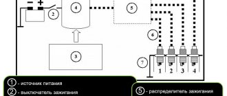
In the photo: diagram of the battery ignition system with digital designation of components:
Structure and internal connections
The ignition coil noise suppression capacitor is a non-polarized capacitor.
Both noise suppression capacitors (ignition coil noise suppression capacitor and ignition coil noise suppression capacitor 2) have the same design.
| Designation | Explanation |
| 1 | Interference suppression capacitor for ignition coils |
Distribution of contact pins in the connector
| Pin | Explanation |
| Kl. 31 | Contact 31, ground |
| U | Supply voltage |
How to understand that a device needs diagnostics
Various signs indicate a faulty capacitor. Headlights that flash in time with the bass of the car speakers mean that the car's electronic components are not receiving enough voltage. In some cases, the signals begin to become distorted, and individual components of the machine do not work correctly.
The ignition capacitor is responsible for producing a spark that ignites the air-fuel mixture in the engine cylinder. If the spark has a weak red color and appears unevenly, if the car cannot be started normally, it is likely that there are problems with the capacitor.
It is important to avoid problems with the ignition capacitor. They arise for three reasons:
The first two options are especially insidious, since the ignition does not immediately fail. The components continue to function, although the spark may no longer have the required power level. The main signs of a breakdown in such a situation are instability of the engine at idle and problems with starting. Be sure to check the capacitor and replace it if necessary! If this is not done, sparks from the breaker will cause the contacts to burn, which will damage the power unit.
Disadvantages of the classic contact ignition system
Among the disadvantages of classical ignition systems, one can highlight the fact that a large current passes through the contact group of the breaker. Consequently, this element wears out very quickly. Sparking also occurs in the high-voltage contacts of the direct housing of the ignition distributor. This is not observed on other systems.
All this in total significantly reduces the service life, and most importantly, the reliability of the entire structure. As for reliability, it depends on many components. In particular, it is influenced by the spark energy, secondary voltage, shape and length. And also the time during which the spark burns. Energy can be calculated if you know three parameters:
But reliability can be determined by voltage. If combustion conditions are normal in the engine cylinders, the air-fuel mixture is ignited by a spark, which has an energy of only 10 mJ.
