The ignition coil is designed to create high voltage, which is then used by the spark plug to produce a spark. Therefore, its proper operation is necessary for the normal functioning of the ignition system. Essentially, the coil is a small transformer, the primary winding of which receives standard 12 V from the battery, and outputs a voltage of several kV. It is used in all ignition systems - contact, contactless and electronic. The reasons for coil failure are typical. As a rule, this is a wire break, insulation damage, or mechanical deformation. Next, we will look at the signs of a malfunction and methods for diagnosing the ignition coil.
The principle of operation of the ignition coil
As mentioned above, the ignition coil is a step-up voltage transformer that converts the resulting 12 V voltage into a voltage of several kilovolts. Structurally, the coil consists of two windings - primary and secondary (low and high voltage, respectively). However, depending on the type of coil, the windings and their arrangement differ.
Let's start the description with the simplest common coil . Here there are 100...150 turns on the primary winding. The winding is wound with insulated copper wire. Its ends are brought out onto the coil body. The number of turns of the high voltage winding is 30...50 thousand (depending on the model). Naturally, the wire used here is of a much smaller diameter. The “minus” of the secondary winding is connected to the “minus” of the primary. And the “plus” is connected to the terminal on the cover. This ensures that the resulting high voltage is removed.
To increase the magnetic field, the windings are wound around a metal core. In some cases, to avoid overheating, the windings and core are filled with transformer oil (it not only cools the system, but also acts as an insulator).
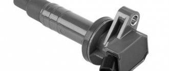
Now let's move on to considering the individual ignition coil . There are also two windings here, but the difference is in their location. In particular, they are wound in reverse order. The primary winding has an internal type core, and the secondary winding has an external type.
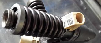
Individual ignition coils are installed in systems with electronic ignition. Therefore, their design is complicated. So, to cut off significant current, a diode is provided in the secondary winding. Another feature of the individual coil is the fact that the resulting high voltage does not go to the distributor (as in classical systems), but directly to the spark plugs. This was made possible by a design that included an insulated body, rod and spring.
Another type of coil is two-terminal . It supplies voltage to two cylinders at once. There are several varieties of them. As a rule, such coils are combined into one common unit, which is essentially a four-terminal ignition coil.
Regardless of the type of ignition coil, its main technical parameter that you should focus on when diagnosing is the resistance of the windings. In particular, the resistance of the primary winding is usually in the range of 0.5...3.5 Ohms, and the secondary - 6...15 kOhms (these values may differ for different coils, so it is better to find reference information specifically for the model that is used in your car ). Measurements are made using traditional instruments - multimeters or ohmmeters. If the obtained value differs greatly from the specified value, then there is a high probability that the coil has failed.
You also need to be aware that each coil has different indicators:
- winding resistance;
- spark duration;
- spark energy;
- spark current;
- inductance of the primary winding.
Therefore, in order to understand how well the coil readings correspond to the norm, it is necessary to clarify the technical characteristics of your individual coil. This will be especially useful if the spark is lost, since the ignition coil is one of the first elements of the system to be checked.
The process of checking all ignition coils on a VAZ-2112
The VAZ-2112 engine with 16 valves uses individual Bosch ignition coils and in order to check them, the following procedure must be followed:
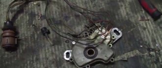
- First of all, we remove each coil from its landing well.
The order of dismantling does not matter. - Then we turn off the power supply and remove them all together as an assembly.
- First of all, we pay attention to its external condition, the absence of cracks and various breaks.
If there is damage on it, we replace it. - The same applies to the spring located inside the coil, look at its position, it should be exactly in the center.
Let's look at its correct location. Despite the fact that many people on the Internet talk about the impossibility of checking a coil with their own hands, it is possible to check it only by knowing their initial values, which are measured in ohms.
- In order not to make false measurements, first of all we check the internal resistance of the wires and the multimeter itself.
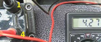
To do this, switch the device to the OM position and connect the probes to each other. What value the multimeter gives is its internal resistance. The value can range from 0.0 to 0.3 ohm. On the multimeter, a value of 00.3 Ohm is normal. - First of all, we “ring” the primary winding, which is located on the first and third contacts; when connecting, the polarity does not matter.
- Depending on the presence of error readings and coil readings, we add up the final indicators.
For example, if the internal resistance is 0.2 ohms and the coil value is 0.7 ohms, therefore the correct value would be 0.5 ohms. Which is the norm. The value of 00.8 ohms is subtracted from the resistance of the multimeter and we get 00.5, which is the norm. - We continue diagnostics with each of the coils.
- If it happens that there are no indications, then we once again check the quality of the connections and the correctness of the connection. If the readings are still zero, then the primary winding on this coil is faulty.
When the readings on the primary winding on all coils are correct and show their values, we proceed to checking the secondary winding.
- To do this, set the switch to 2000 kOhm mode.
- Next, we place the multimeter probe on the coil, observing the polarity, black to pin 2, which is located exactly in the middle of the connector, and the red probe to the spring, inside the rubber plug.
- Three-digit values will mean the coil is working properly, and infinity values will indicate its failure.
Such designations indicate the serviceability of the ignition coil.The number “1” stands for infinity and indicates a faulty ignition coil.
- Please note that if you cannot measure the resistance correctly the first time, you can wipe the fixed elements from dirt and deposits, since dirty parts can interfere with the signal output.
- When replacing old coils with new ones, you should strictly use analogues, taking the faulty part with you to the store in advance.
Signs of trouble
There are several characteristic signs of a faulty ignition coil. Among them:
- the motor begins to “trouble”, and this problem gets worse over time;
- in the cold the engine “troubles” until it warms up;
- interruptions in engine operation in wet weather;
- When you sharply press the accelerator pedal, there is a failure in the engine.
If the coil is faulty, on cars with an ECU, the Check Engine icon on the dashboard is activated. However, the listed signs may also indicate other malfunctions, in particular with the spark plugs. But if at least one of them appears, you need to diagnose the ignition coil(s). When connecting a diagnostic scanner, it may show error P0363.
Examination
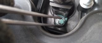
3. Press the lock of the wiring harness block.
While holding the latch in this position, disconnect the wire block from the ignition coil of the first cylinder.
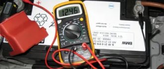
4. Turning on the ignition, use a voltmeter to measure the voltage at terminal 3 of the wiring harness block (the numbering of the terminals is marked on the ignition coil).
5. Similarly, we check the supply voltage to the ignition coils of the second, third and fourth cylinders.
Comment. The voltage at the terminal must be at least 12 V. If the voltage does not reach the block or it is less than 12 V, then the battery is discharged, there is a malfunction in the power circuit, or the ECU is faulty.
Warning! When the voltage measurement is complete, turn off the ignition.
6. Using an ohmmeter, measure the resistance between the coil terminals. The electrical resistance between pins 1-3 should be close to zero (about 1 ohm). The resistance between pins 1-2 and 2-3 should be high (tend to infinity).
The faulty coil must be replaced.
Causes of malfunctions
There are several reasons why the ignition coil completely or partially fails. Among them:
- Mechanical damage . This may be simple aging, due to which the insulation is destroyed. There is also the possibility of oil leaking through the seals, which gets onto the insulation or coil body and destroys them. Repair in this case is hardly possible, so the best option would be to completely replace the unit.
- Damage to the contact connection . In warm weather, this may be caused by moisture getting into the engine compartment. For example, during heavy rain, driving through deep puddles, washing a car. In winter, it is likely that the reel will get hit with the composition that is sprinkled on the road surface to combat ice.
- Overheating . Individual coils are often susceptible to it. Overheating can significantly reduce the life of the ignition coils. The overheating process is difficult to control, but try to use high-quality coolant and ensure that the engine cooling system is working properly.
- Vibrations . They are especially harmful to individual ignition coils. Vibrations usually come from the cylinder head (cylinder head). To reduce the number and amplitude of vibrations, make sure that the engine is operating in normal mode (without detonation and with working mounts).
Ignition coils are quite reliable and durable components, and their failure is most often associated with aging and/or insulation breakdown. Next, we will consider methods for diagnosing coils.
Video “Recommendations for diagnosing MH”
Important recommendations and features of diagnosing MZ in VAZ 2112 cars are shown in the video below (author - AutoElectrika Diary channel).
The car jerks, there is no traction, vibration is felt, or the engine is rough; all these are symptoms of improper operation of the individual ignition coil (IIC). Other signs of a faulty ignition coil are the presence of errors 0301, 0302, 0303 and 0304, indicating misfire in one of the cylinders. Let's look at a few simple ways to check the ignition coil with your own hands.
It is worth noting that the process of checking IKZ on modern Lada cars (XRAY, Vesta, Largus, Granta, Kalina and Priora) does not have significant differences. All actions are performed in the same way.
How to check the ignition coil
There are two main ways in which you can independently check the performance of the ignition coil. Let's list them in order.
Checking the VAZ ignition coil
Checking the Cherry Tiggo ignition coil
Spark test method
The first of them is called “to spark” . Its advantage is the ability to perform it in “marching conditions”. Among the disadvantages, it is worth noting that it is labor intensive and inaccurate, since the causes of the detected malfunctions may not be the ignition coil at all. To perform diagnostics, you will need a spark plug wrench, a known good spark plug, and pliers.
First, visually check the integrity of the high-voltage wiring insulation. Starting with the spark plugs and ending with the coil. In this case, the ignition must be turned off (the key is in position 0). If everything is in order with the insulation, the algorithm for further actions will be as follows:
- Remove the tip from the spark plug of the first cylinder and connect it to the previously prepared working spark plug.
- By yourself or with the help of an assistant, turn the ignition key to position II (start the car).
- If the coil is working properly, a spark will appear between the electrodes of the spark plug. In this case, you need to pay attention to its color. A normal working spark has a bright purple hue. If the spark is yellowish and weak, then there are problems with the wiring or coil. If there is no spark at all, then the ignition coil is faulty.
- Repeat the described steps for all coils if they are individual in the machine.
Be careful when working with the ignition system. Do not touch live parts that are live.
If you do not have a known working spare spark plug, you can remove any spark plug from the engine. To do this, disconnect it and use a spark plug wrench. In this case, you can check the coil on all available spark plugs. This way you will also check the condition of the spark plugs.
If the engine has individual coils installed, you can check them by replacing them with other spark plugs. In this case, it is better not to touch the wiring so as not to damage its integrity.
Ignition coil module
"Spark in a syringe" method
The process of checking the coil using such a homemade device is quite simple. To do this, you need to connect the coils one by one to the spark plug of the resulting “device”. Attach the crocodile fastener to the ground of the machine body. While changing the tested coils, the engine must be turned off and then restarted.
Initially, using a piston, you need to set the minimum gap between the wire on the piston and the electrode (1...2 mm). And by adjusting the distance from the wire on the piston to the electrode on the spark plug, visually watch the process of a spark appearing between them. The maximum distance in this case will be different for different cars, and it depends on the quality and condition of the spark plug, the condition of the car’s electrical system, the quality of the “mass” and other factors. Typically, a spark during such tests should appear at a distance between the electrodes from 1...2 mm to 5...7 mm.
Before each test of the operation of the resulting device, it is necessary to disconnect the connector from each injector so that fuel does not flood the cylinder during testing.
The main thing that can be accurately judged during such tests is a comparison of the condition of different coils by cylinder. If there is a malfunction or breakdown, this will be visible by the length of the spark compared to more or less serviceable coils.
Insulation resistance test
Another popular test method is to measure the insulation resistance value of the wires in the coil windings. To do this, you will need a multimeter that can measure resistance. It is better to remove the ignition coil from the car to make work more convenient. The measurement procedure is simple. The main thing is to know where the terminals of the primary and secondary coils are located, since measuring resistance must be checked on both of them.
Before starting work, make sure the multimeter is working properly. To do this, turn on the resistance measurement mode and connect the probes to each other. There should be 0 on the screen.
Two multimeter probes are connected (touched) in pairs to the terminals of the primary winding. The resistance value should be in the range of 0.5...3.5 Ohms (some coils may have more, you will find the exact information in the reference literature). A similar procedure must be carried out with the secondary coil. However, here the range of values will be different - from 6 to 15 kOhm (for similar information, check the reference literature).
Procedure for measuring the insulation resistance of the ignition coil
If the value is small, it means that the insulation in the winding is damaged, and you are dealing with a short, most likely interturn, circuit. If the resistance is too high, this means that the winding wire has broken and there is no normal contact. In any case, it is necessary to carry out repairs, that is, rewind the winding. However, in most cases it is better to simply replace the ignition coil , since this method will save you from unnecessary hassle and expense. This applies to almost any car, because the cost of repairs will exceed the price of the coil itself.
If you are dealing with individual or two-terminal coils, then the situation here is somewhat different. The value on the primary winding should be similar. As for the “secondary”, the resistance value will be identical at both terminals. If a coil with four terminals is installed on the machine, then the check must be done on all terminals.
Also note that polarity is important when measuring secondary resistance. In particular, touch the central terminal (“ground”) with the black probe of the multimeter, and touch the tip rod with the red one.
The oscilloscope will show everything
The most professional method for checking a coil is to use an oscilloscope. Only he is able to provide complete information about the state of the ignition system, and in particular the ignition coils. Therefore, in difficult cases it makes sense to use an electronic oscilloscope and additional software. This is especially true when there is a so-called interturn short circuit on secondary voltage coils (with high voltage).
Checking the ignition with an oscilloscope
Checking the ignition system with an oscilloscope allows you to identify a malfunction of a specific component or simply diagnose the condition using oscillogram pulses. More details
If you use an oscilloscope to take a graph of the operating voltage values in the dynamics (seen in the figure), then you can understand from it that the cause of the possible malfunctions described above will be the ignition coil. The fact is that when an interturn short circuit occurs in the secondary coil, the energy that could potentially be stored in this coil itself decreases, and this, in turn, leads to a decrease in the spark burning time, that is, misfire. This is especially noticeable when you sharply press the accelerator pedal.
The reel is intact
The coil is broken
Design and principle of operation
How to check current leakage on a car with a multimeter
It is probably clear to all drivers that the main purpose of the high-voltage coil on a car was and remains one thing: to set fire to the air-fuel mixture. To do this, it generates high voltage, the value of which is about 40 thousand volts.
It is a transformer that increases the low voltage of the battery to high. The transformer consists of two windings, one of them is primary and the other will be secondary, which are wound with copper wire on an iron core.
The primary winding is wound on the core, and the “secondary” is wound on top of it. The entire structure is covered with a casing. If the low-voltage winding has only about 150 turns, then the “secondary” already has several thousand.
There are no high-voltage wires, since it is placed directly on the spark plug. When, at the right moment, an impulse is sent from the engine control unit to the “primary” of the coil, a magnetic field is excited around the core, which contributes to the appearance of high voltage in the “secondary”. In this case, the spark plug plays the role of a spark gap that ignites the working mixture in the engine cylinders. The coil has a protective shell, and inside it is additionally installed a spring and a diode, which is designed to quickly cut off high-voltage pulses.