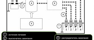
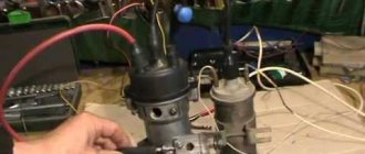
Connection diagram for the ignition module VAZ 2110 injector 8 valves
We check the ignition module on the injection VAZ-2110 8 valves with our own hands
At different times, different engines were installed on the VAZ-2110 car, both carburetor and injection. However, regardless of the type of power system and the number of valves (8 or 16), all engines are assembled on the unit base of the old engine 21083 and 21093. The most progressive of these engines is the 16-valve 1.6-liter VAZ 21124 engine with a power of 89 horsepower. Today we will touch on the ignition module for 8-valve engines 2111 and 21114 (1.6 l), check its performance and find a suitable replacement for the failed module.
Version of the module on the 8-valve VAZ-2110
The top ten was equipped with two 8-valve engines of different sizes - 1.5 (2111) and 1.6 liters (21114). The ignition modules for these engines are different.
- The one and a half liter engine has a module with article number 2112-3705010,
- and the 1600 cc engine is equipped with module 2111-3705010.
A module for a 1.5 liter engine costs about 1500-2100, and the second one is 500 rubles cheaper.
Which is better?
SOATE devices manufactured in Stary Oskol have proven themselves to be the most reliable ignition modules.
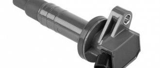
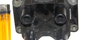
Module structure
The module consists of two ignition coils and two high-voltage switch switches.
The coil generates a high voltage pulse, and it is a simple transformer with two windings, primary (induction voltage about 500 V) and secondary (induction voltage at least 20 kV). All this is assembled in a single housing, on which there is a connector for signal wires (from the engine control unit) and four terminals for high-voltage wires.
The module operates on the principle of an idle spark - it distributes sparks in pairs to cylinders 1-4 and 2-3 according to impulses transmitted from the ECU.
Malfunctions of ignition modules on the VAZ-2110. DIY diagnostics
The main task of the module is to distribute a high-quality spark sufficient to ignite the working mixture.
If this does not happen, problems begin with the motor:
- power drop;
- high gasoline consumption;
- failures during acceleration;
- unstable idle speed;
- engine failure when starting.
Signs
- If one of the module coils completely fails, then two cylinders do not work. This is clearly visible even to the naked eye - the engine is feverish at idle, starting is difficult, fuel consumption is sky-high, loss of dynamics.
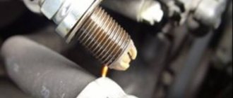
- To eliminate all other components of the ignition system, make sure that the spark plugs are in working order. To do this, unscrew them and check the spark on each of the spark plugs by cranking the engine with the starter and placing the spark plug with the high-voltage wire on the head so that the body (threaded part) of the spark plug touches the engine mass. If there is no spark or it is weak, replace the spark plug with one that is known to work.
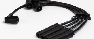
- If this does not lead to anything, check the high-voltage wires. Thus, we will exclude spark plugs, caps and high-voltage wires from the list of non-working elements. Next we will check the ignition module.
How to check the ignition module?
- First of all, we carefully inspect the module body. There should be no chips, burns or cracks on its surface. A module with a damaged casing is replaced without any hassle.
- If the spark is unstable only on cylinders 1-4 or 2-3, one of the module coils is probably damaged. In any case, we will conduct a comprehensive check of the device. For this we will need a regular multimeter.
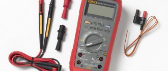
Diagnostic procedure
The diagnostic procedure can be as follows:
- Disconnect the connector with signal wires from the module.
- Turn on the ignition and check the voltage at terminal 15 (central) of the control wire block. The rated voltage is 12 V. A drop or absence of voltage when the battery is charged indicates that the engine control unit does not supply power to the module. This means the reason lies in the ECU.
- We remove the high-voltage wires, unscrew the module mounting bots and remove it.
- We check the resistance of the primary windings of the coils - put the multimeter in resistance measurement mode and take readings from the rightmost and central terminals, then from the leftmost and central terminals. The nominal resistance of the primary windings is approximately 0.5 Ohm.
We measure the resistance of the secondary windings between terminals 1-4 and 2-3 high-voltage wires. Nominal value: 5.4 kOhm. If the readings do not correspond to the nominal value, the coil is not working correctly.
Check the module for a short circuit. To do this, install one tester probe on the central pin 15, the second on the metal body. The device should show the absence of a short circuit (one or infinity). Otherwise, one of the coils has shorted to the housing.
Errors
A module malfunction can also be determined using an error scanner. Error codes associated with the module are:
- R-3000, R-3001, R-3002, R-3003 and R-3004 - gaps in sparking, the module itself, spark plugs, high-voltage wires or the ECU may be to blame;
- R-0351 - the coil of cylinders 1-4 does not work;
- R-0352 - the coil of 2-3 cylinders does not work.
The scanner readings do not yet indicate problems with the module itself.
It is possible that the spark plugs are not working or the high-voltage wires are broken, but if we initially diagnosed them, then the fault lies entirely with the ignition module. In this case, we can repair it ourselves, or buy a new one, which is faster, easier and guarantees uninterrupted operation of the ignition system. Good luck to everyone, strong spark and good roads!
Video on how to check the ignition module with a multimeter
If you find an error, please select a piece of text and press Ctrl+Enter.
Instructions for checking the ignition coil with a multimeter
Verification of the described element is a three-step process. It starts with careful preparation. Then a visual inspection is carried out and everything ends with testing the system using special instruments.
The functioning of the coil can be checked on professional diagnostic stands in special services and dealership centers. To do this yourself, you will need to use a multimeter. This tool is a universal diagnostic device with the widest possible range of applications.
You may also be interested in our specialist’s article on how to check a lambda probe with a multimeter.
Preparatory operations
Before you begin diagnosing the ignition coil itself, you will need to prepare a multimeter. This device is able to determine accurate voltage readings and the level of electrical resistance in Ohms.
Modern cars have different types of ignition coils. The parameters of each model are indicated by the PTS of each car. Such indicators need to be known so that diagnosis can be made. The test consists of identifying such a parameter as the resistance of the ignition coil, that is, the resistance of the secondary and primary windings. If during the verification process it is not possible to detect resistance indicators, it will be possible to rely on generally accepted signs.
Visual inspection
External system characteristics may vary slightly depending on the model. The following characteristic elements differ:
- lid;
- frame;
- centrally located terminal;
- two contacts.
During the visual inspection of the element, you will need to carefully examine the condition of the body and try to detect cracks, chips and burnt areas on the surface. Due to the fact that the housing is made of hard rubber and, accordingly, does not allow current to pass through, the malfunction of the device will mostly be associated with internal damage.
If, in the process of studying the state of the external characteristics of the coil, certain problems are identified, the element will need to be replaced with a new one. The new coil must strictly comply with all the necessary technical characteristics - winding resistance, duration and spark energy. If no problems with external characteristics are detected, you can proceed to checking the primary and secondary windings.
Checking the primary winding
At this stage, you need to connect the multimeter to the negative and positive terminals, and set the device to measure the resistance level. Despite the fact that devices from different cars are characterized by different resistance levels, the indicator fluctuates in the range of 0.4 - 2 ohms.
If during the diagnostic process the device displays a value within this range, we can judge the serviceability of the device. The display of a value of 0 Ohm directly indicates that a short circuit has occurred in the winding. If the resulting value is infinity, a break has occurred in the electrical circuit. After checking the primary winding, you can begin to detect problems with the secondary.
Checking the secondary winding
During this test, the multimeter probes will need to be connected to the positive contact and to the high voltage wires. If the device has a special plate core, the resistance parameters will be in the range of 6 - 9 kOhm. All other coil categories will exceed 15 kOhm.
Comparison of measurement results with normalized values
After checking and determining the resistance level of the two categories of windings, all the readings obtained must be compared with the standard parameters established by the manufacturer. Thoroughly checking a dual coil is a more difficult task. The primary winding in coils of this type is connected directly to the connector.
The standard double coil circuit is somewhat different from the usual one and knowledge of it is necessary in the process of checking the primary winding. The secondary winding will ring without any problems. For this purpose, it is enough to simply connect the tester to a pair of high-voltage leads.
Do-it-yourself repair of the VAZ 2110 ignition module, how to check and replace
The motor control system includes a wide range of different elements, each of which plays its own important role.
In some situations, high voltage disappears on several or even one cylinder. The reason for this may be the ignition module on the VAZ 2110, or rather its malfunction.
It should be noted that replacing the ignition module of the VAZ 2110 may not be necessary. First try to repair it, diagnose and fix the problem.
Design
Disassembled module
Structurally, the ignition module includes two main elements:
- 2 ignition coils that generate high-voltage pulses directed to the spark plugs;
- Dual channel switch.
The reasons for failure can be different, ranging from interruptions in the operation of the engine, ending with an unexpected stop of the power unit. Please note that the "Check Engine" light does not turn on.
Malfunctions
Diagnosing the problem will not be a problem for you if you understand a little electrical engineering and know how to work with a device such as a multimeter. If not, we recommend that you contact a specialist. A professional check of the ignition module of a VAZ 2110 using a multimeter will give you the result you need and will allow you to answer important questions.
Do not rush into repairs, since the problem may not lie in this element at all. Before checking the ignition module on a VAZ 2110, consult with professionals and arrange a check of your car. You will have to spend time and money on this, but it is better to be prepared for troubles.
Quite often, short-term breakdowns occur in the system, which soon disappear. The check engine light does not detect them, but they remain in the controller and are entered into its memory. If you try to read errors on the controller with a tester, it will not show anything, since there were problems, but now they are gone.
We have already become familiar with the signs of a malfunction in the VAZ 2110 ignition module, and the reasons for such situations may be dirty contacts, poor ground connection, electrical interference, and so on.
Repair
So, for the VAZ 2110 the most common problem is the disappearance of voltage on cylinders 2 and 3. After some time, the engine starts working normally again if you press the rear plate of the module.
You should not put up with such a situation; it is better to immediately check the functionality of the unit, restore or replace it completely.
WHAT ARE THE FOLLOWING SIGNS OF MALFUNCTIONS?
When asked what are the signs of a malfunction in the VAZ 2114 ignition module, any driver will say without hesitation that there is no spark at the spark plugs. This is partly true, but there are several other possible reasons for the failure of this device. You can see the following:
- The dynamics disappeared during acceleration, dips in engine performance appeared when the gas pedal was sharply pressed to gain speed;
- A decrease in engine power has become noticeable; drivers say in such cases that the engine does not “pull”;
- The idle speed floats a lot;
- There is no spark on one of the pairs of spark plugs.
When signs of a faulty ignition coil appear, the test should begin with the spark plugs, which do not work, then the sensor indicating the position of the crankshaft is the last module to be checked.
Types and differences of VAZ ignition coils
A car's gasoline engine operates by burning fuel. To ensure ignition, an electric spark is required, which is formed between the electrodes of the glow plug. They have a small gap that the spark must overcome. This is feasible when high voltage (tens of thousands of volts) is applied to the spark plug.
The vehicle's on-board system is not designed for such loads, and the equipment that supplies electricity is not capable of producing such values.
To solve this problem, a coil is introduced into the car's ignition system, creating a high voltage. A component of the vehicle's ignition system converts low voltage to high voltage (depending on the characteristics of the part from 6-12 V to 35,000 V). The tasks performed by the coil are determined by the structural features of the element. It consists of primary and secondary windings, which are housed in an insulated housing.
Attention! If malfunctions occur, it is recommended to check all engine components: from the valves and cylinder block to the ignition coil or module.
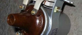
Classic, family 2101-2107
Domestic VAZ cars of the “classic family” (models 2101-2107) are equipped with carburetor and injection engines. Cars with carburetors have an ignition coil (or "bobbin") installed. The arrangement of the element is as follows: the part is mounted on the left mudguard in the engine compartment of the car, and is attached to the body using two nuts.
Cars with installed injectors (VAZ 2107) have an ignition module. It is mounted on the cylinder block of the car's power unit. The part functions together with the engine's electronic control unit, and the ignition coils are included in the design of the entire module.
The ignition module used is a universal model (installed on other domestic cars)
For the injector and as part of the BSZ, a coil 027.3705 is used, analogous to 27.3705 (ATE-2).
The characteristics of the “injection version” of the VAZ ignition coil are as follows:
Operating temperature from -40° C to +85° C Resistance value: primary winding (0.45+0.05) Ohm secondary winding (5+0.5) kOhm Supply voltage 12 V Overall dimensions 72x156 mm, oil-filled design
"Sputnik", 2108-21099
On the VAZ 2108-21099 model, ignition coils marked 027.3705 are also installed.
Tenth models, 2110-2112
On the VAZ 2110-2112, ignition coils are installed on both injection and carburetor engines (nowadays they are practically not found). For injection models VAZ 2110-2112, an ignition module marked 042.3705 is provided, designation according to the documentation of OJSC AvtoVAZ 2112-3705010-03, some models are equipped with individual coils 2112-3705010-12
Lada Samara, 2113-2115
On carburetor models of VAZ cars of the Samara family (2113-2115), ignition coils 2111.3705 (analogous to Bosch F000 ZS0 211) are installed. These coils have a 3-pin connector and are used for VAZ cars with a microprocessor internal combustion engine control system based on the M7.9.7 controller or its analogues with 8-cl. engines.
Kalina, 1117-1119
A more modern VAZ model, Lada Kalina, is equipped with an ignition module marked: 2112-3705010-12. It has the following characteristics:
Load voltage 1MΩ +25pF>24kV
Spark charge duration 1.14-1.5 ms
Operating temperature range from -40 to +140 degrees C
Rated supply voltage 12V.
Priora, 2170-2173
The Lada Priora is equipped with the same ignition coils as the Kalina. The coil is marked 2112-3705010-12. Just as in the case of Kalina, Priora is equipped only with injection engines, so carburetor ignition coils or “bobbins” cannot be installed on the car.
To summarize, it is worth saying that when choosing an ignition coil for a car, it is necessary to take into account the marking of the part, its compatibility with a particular model of the domestic automobile industry. Despite the high interchangeability, attention is also paid to the overall dimensions of the part and the type of fastening in the engine compartment of the car. You can purchase coils or ignition modules for domestic “classics”, “Samara” and “Sputniks” in our online store with a few clicks of a computer mouse.
IGNITION MODULE DEVICE FOR VAZ 2115
This module consists of two high-voltage transformers and two control units (electronic), enclosed in a durable plastic case with four outputs of high-voltage wires. Electronic control units are also commonly called ignition coils, and one of them - “working” - is connected to the spark plugs of the first and fourth cylinders of the power unit, the other - “idle” - with the spark plugs of the second and third.
This type of connection, made using high-voltage wires, ensures synchronous “slippage” of the spark pulse in the cylinders of the power plant.
Thus, we can formulate the functional purpose of the ignition module - generating high-voltage spark pulses on the spark plugs of the vehicle’s power unit.
The VAZ 2115 ignition module is controlled by a controller whose operating functions include processing data received from vehicle system sensors: coolant temperature, rotation speed and position of the crankshaft, air flow, presence of detonation, etc.
Ignition module 55.3705 (ignition coil) for VAZ 2108-2112
- Manufacturer: Omega
- 0 reviews
- Description
- Characteristics
- Video
- Reviews 0 ? '(' + product.reviewsCount +')' : »>>
Dear customers, in order to avoid errors when sending the ignition module, please indicate your car model, year of manufacture and number of valves in the “Comment” line.
The ignition module 55.3705 is designed to work as part of microprocessor control systems for internal combustion engines of automobiles. The ignition module is installed on vehicles in accordance with its application.
The ignition module is powered from the vehicle's on-board network with a rated voltage of 12V, the negative pole of which is connected to the body. The ignition module generates high-voltage pulses on the spark plugs of an internal combustion engine of a car. The ignition module contains two ignition coils and a switch. The ignition module is controlled by the vehicle controller.
Structurally, the ignition module 2112-37050010 is a block with an electrical connector, which consists of two two-terminal ignition coils. At the top of the coil there are four high-voltage terminals.
The ignition module is not difficult to find, open the hood of your car and pay attention to the spark plugs, wires will come from these plugs, so look where the wires lead and after finding it, you will see a small square-shaped box in front of you, which is called the ignition module .
Other articles of the product and its analogues in catalogs: 55.3705, 21.12370-5010, 042.3705, 2112-3705010-02, -03
Product features: The ignition module (catalog designation "Omega" 55.3705) converts control unit pulses into high-voltage pulses on the spark plugs of the vehicle's internal combustion engine.
VAZ 2108, 2109, 2110, 2114, 2115.
Technical characteristics: Operability at ambient temperature: from - 40 °C to + 130 °C.
Rated supply voltage: 12V.
Primary winding current: no more than 6.4 A.
Secondary voltage with a primary current of 6.4 A and a shunt load of 50 pF: 28 kV.
Spark discharge energy (more): 50 mJ.
Spark discharge duration (more): 1.5 ms.
Any breakdown is not the end of the world, but a completely solvable problem!
AvtoAzbuka online store, repair costs will be minimal.
Just COMPARE and BE SURE.
Don't forget to share the information you find with your friends and acquaintances, because they may also need it - just click one of the social networking buttons located above.
Communities › VAZ: Repair and Modification › Forum › VAZ 2110, injector, 8 cells, won’t start, no spark
Good day to all. Yesterday my friend’s car stopped starting; as it turned out, there was no spark at the spark plugs. A new Ignition Module, new explosive wires, and a new DPKV were purchased at the store. ECU January 5,1,1 was replaced with exactly the same one that was known to work. But the engine still doesn't want to work. So far I have found out that on the chip going from the ECU to the Ignition Module, on the last contact (D) there is 12 volts when the ignition is turned on, and on the penultimate one there is ground. So, as I understand, the control signals for sparking go through the 1st and 2nd connectors (A and B). But how can you find out whether these signals are reaching the coil? I connected a low-power 5w light bulb to these connectors, that is, one end to the ground of the car, and put the other end into connectors A and B and turned the starter, the light did not light up. Maybe a very weak current is generated there? Or do you need to dig in the direction of the break in both wires (which is unlikely)?
By the way, there is gasoline, the pump pumps, there is pressure when you press the nipple. The fuses are all intact, the relays are all working.
Check the crankshaft position sensor.
The DPKV itself is new. The tester showed 600 Ohms with something, I don’t remember exactly. Tomorrow I’ll take it off and use a magnetic screwdriver nearby to check whether the fuel pump will pump, it seems they wrote that in this case the fuel pump should pump up gasoline.
Are there other ways to check it?
I need to take a look at the pulley itself. I connected the LED strip to the DPKV wires and when I turned the starter, the strip blinked and pulses were sent. I was also looking for a spark, you can also connect it to the contacts of the coil, there should also be an impulse.
Thanks for the advice. I'll try to check with the LED. What could be wrong with the pulley?
Could turn the pulley
All belt teeth are intact. Although I heard that the pulley can turn on its own. Today I will remove the belt and set the ignition to a new one.
just set the marks, and the 20th tooth of the pulley will have to look at the dpkv
The DPKV itself is new. The tester showed 600 Ohms with something, I don’t remember exactly. Tomorrow I’ll take it off and use a magnetic screwdriver nearby to check whether the fuel pump will pump, it seems they wrote that in this case the fuel pump should pump up gasoline.
Are there other ways to check it?
The sensor itself is new, but how do the connector and the wire going from it to the ECU feel?
I haven’t tried calling, but today I’ll try to ring the wires from the DPKV chip to the ECU, and the rest in one.
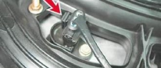
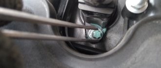
And the gap between the sensor and the gear
By eye it seems to be 1 mm, as they say. It's hard to say exactly. But today I’ll try to move it in the nest. Or I’ll take something to insert into the gap to set it exactly 1 mm. Thank you.
Yes, look at which tooth the sensor is looking at, it should be 20.
I connected the LED to the DPKV terminals, the LED began to blink on one of the terminals. Based on the first signs, we can assume that impulses are coming from the ECU to the DPKV, everything seems to be normal there. I also threw an LED onto terminals A and B of the chip from the ECU to the Module, and here I was a little puzzled. When the ignition is turned on, there is constant voltage at terminals A and B of the module chip when an LED is connected to it... That is, the LED does not blink, but is constantly on.
After scouring the Internet a little, I found out that the master pulses for sparking should appear at these terminals. To be more sure that everything is so, I removed the chip from the module on my car and checked pins A and B with an LED, and so it blinks, as people say.
Today I found out another nuance from a friend that he forgot to tell me. It turns out that one of the wires on the Ignition Module chip started smoking and melted... Which one is not clear.
Listen, if there was a short circuit, look at the fuse with the switch at the passenger's feet and the wiring there in the same place
I visually inspected the wiring and rang each wire, and also rang for short circuits between them, 4 wires that go from the Module chip to the brains. Everything is alright, b-ro-de-by. Fuses are intact
Eventually. Fuses 3 pcs. in order. Relay 3 pcs. in order. A check is lit on the display, the brains seem to be in order, but I replaced them with obviously working ones from my car. So it's ok. The fuel pump is pumping, there is pressure in the rail, the spark plugs are filling, the injectors are working. The belt is intact, the ignition is set according to the risks, the 20th tooth is exactly opposite the DPKV. The pulses on the DPKV chip come through one of the wires, the LED is on, the second one is not, but it seems like it should be... Also, if you turn on the ignition and move the DPKV chip connector, the fuel pump pumps up gasoline, the same way it pumps gasoline if you remove the DPKV and move the magnetized one screwdriver nearby. The gap between the sensor and the pulley, as seen in the photo, seems to be 1mm. I looked at it on my car, the gap is exactly the same as mine. I measured it with a metal strip, 1mm thick, and stuck it in the gap. The ignition module is new. The explosive wires are new, the resistance is normal. The DPKV is new, the resistance is normal. Just like on the old sensor, by the way. All wires from the Module chip to the ECU ring, and do not ring among themselves, they are all in those connectors where they should be according to the diagrams.
Now what's wrong. When connecting the LED to terminals A and B of the Module chip, there are no sparking impulses. 1 pulse only occurs when the ignition key is released. That is, when I turn the starter, there are no signals, but at the moment when I release the key and stop turning the starter, at that moment one pulse appears. I don’t know if this is important, but here it is. Also, the next time the ECU was connected, the injectors stopped functioning. Honestly, remembering all the actions that were performed on the car, I’m not entirely sure that the injectors were working all this time, although the spark plugs were wet from gasoline. In general, the injectors do not open and there is no spark.
So, the problem is solved.
The whole point was that the new purchased Ignition Module chip had a trick... It turned out that the wires inside the chips were rearranged. And I called and checked for the presence of ground, plus and control signals from the wires that go to this chip. Moreover, I noticed that A and B were swapped almost from the very beginning, when I started calling the wiring from the ECU to the Module. But for some reason I didn’t think to check that plus instead of mass. It never even occurred to me that this could happen))
Pinout, connection diagram and check of the VAZ ignition coil
Today we will look at the design and diagrams of ignition systems for VAZ cars of all major models. Since carburetor versions of VAZ are practically history, we will dwell in detail on the ignition systems of injection cars. Their ignition system is based on an electronic ignition module. We also recommend that you carefully consider the choice of spark plugs and the quality of high-voltage wires, because the quality of the spark and, accordingly, the operation of the ignition system as a whole will depend on them. The information is intended as a reference guide for self-repairing a car.
Pinout and diagram of the VAZ ignition coil
Pinout of ignition coil modules for various car models of the VAZ family:
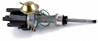
Ignition VAZ 2101
1 – generator; 2 – ignition switch; 3 – ignition distributor; 4 – breaker cam; 5 – spark plugs; 6 – ignition coil; 7 – battery.
Ignition VAZ 2106
1 – ignition switch; 2 – fuse and relay block; 3 – EPHH control unit; 4 – generator; 5 – solenoid valve; 6 – microswitch; 7 – spark plugs; 8 – ignition distributor; 9 – ignition coil; 10 – battery.
Ignition VAZ 2108, 2109
Ignition VAZ 2110
Ignition VAZ 2111
Ignition VAZ 2112
Checking the ignition coil for malfunctions
What malfunctions of the VAZ 2106 ignition coil can be determined by checking? If we exclude such defects as unstable contact of the product with the electrical wiring due to weak fastenings, then the main malfunction of the ignition coil is a weak spark, which cannot “break through” a gap of more than 5 mm. A working ignition coil in good condition should “break through” a gap of about 15 mm. Otherwise, the “reel” is considered faulty.
A routine check of the ignition coil is carried out on a product located in the electrical circuit of the vehicle. The main goal of the activities being carried out is to measure the resistance of the ignition coil of the VAZ Shokha, namely, to measure the resistance values of all windings and the insulation resistance to ground.
Operating procedure:
- Disconnect the negative wire from the battery.
- We remove the electrical wiring elements from the output contacts of the coil.
- To carry out repair work, you need to acquire a set of ordinary plumbing tools, a megohmmeter or other similar device.
- We measure the resistance of the primary winding; to do this, we connect the megger contacts to the low voltage terminals, which should be cleaned of dirt. For products with number 3122.3705 according to the nomenclature, the resistance of the ignition coil should be 0.43 ± 0.04 Ohm. For products with number 8352.12 according to the nomenclature, the resistance of the ignition coil should be 0.42 ± 0.05 Ohm.
- Then we test the resistance of the secondary winding, i.e. We connect the limit switch of the megohmmeter to output “B” of the product, and connect the other output to the high voltage contact. For products with number 3122.3705 according to the nomenclature, the resistance of the ignition coil should be 4.08 ± 0.40 Ohms. For products with number 8352.12 according to the nomenclature, the resistance of the ignition coil should be 5.00 ± 1.00 Ohms.
- And at the final stage it is necessary to test the insulation resistance to ground, i.e. We connect the first output of the megger to the body of the product, and the second in turn to three output contacts - 2 low voltage channels and 1 high voltage channel. All megohmmeter measurements must be at least 50 Megohms. If the measurement indicators are different, it is necessary to replace the product.
As for the VAZ 2106 injector ignition coil, engines of this type do not use a distributor-breaker. It uses 2 ignition coils, which are placed on the cylinder head cover. The network voltage is tested by a special controller. An ignition coil with numbers according to the nomenclature 3012.3705 or 406.3705 is used.
Most often, these products become faulty due to overheating or a short circuit between the turns of the windings, due to the operation of the power plant with excessive spark plug gaps or lack of contacts in the joints of high voltage wires.
Checking coils without dismantling is carried out in 2 ways. To carry them out you will need a megohmmeter and a set of keys:
- First way. We remove the tip from the working spark plug, install another spark plug into it, bring it to the block body and start it using a starter. If there is a spark, then the product is working properly.
- Second way. The check is carried out with a special device for diagnosing the presence of a spark plug. We disconnect the high-voltage high-voltage wires from the product and connect the diagnostic device. We turn the crankshaft of the unit using the starter, and a spark should appear in the discharge device of the electrical appliance.
Checking the product by measuring the gap of the high voltage wire to ground is not carried out, because the controller may become faulty.