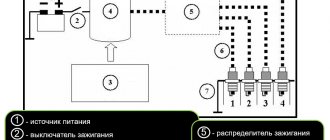
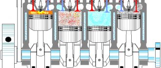
The ignition of the working mixture in the cylinders of gasoline internal combustion engines is carried out by an electric spark. For reasons of electrical safety of the driver and passengers, 12-volt electrical equipment is used in the car. The voltage removed from the generator and battery is not able to create a powerful spark. The problem is solved by increasing the voltage, which is removed from the ignition coil. The latter is a step-up transformer well known in electrical engineering.
Features of the high-voltage part of the ignition system
Wires for transmitting high voltage to spark plugs have the following features compared to conventional ones:
- Increased electrical strength of insulation, designed for voltages of 40 kV and ensured over a long service life.
- They are made in a shielded version, which makes the normal functioning of on-board electronic devices possible.
The need for the latter is due to the fact that high voltage in the ignition circuits is created due to an abrupt change in the input current of the coil. A sudden voltage drop expands the spectrum of the flowing current and, when it coincides with the operating frequencies of electronic equipment, interference appears, which leads to disruption of normal functioning.
The design of the high-voltage ignition wire is designed for operation in the harsh conditions of the vehicle engine compartment. First of all, this is a wide temperature range: from -40 to +100°C. In addition, the wire has increased vibration resistance.
Methods for checking high voltage cables
Diagnosing a high voltage wire is not particularly difficult. There are three verification methods.
Visual inspection
It is necessary to carefully inspect the insulation for cracks and abrasions. The malfunction can be determined by ear - when the engine is turned on, characteristic clicks will be heard. If you conduct an inspection in the dark, you will notice sparks.
Checking resistance with a multimeter
Using the device, you can identify which cable has a problem. If one or more of them malfunctions, voltage to the spark plugs begins to be supplied intermittently, which causes engine malfunctions.
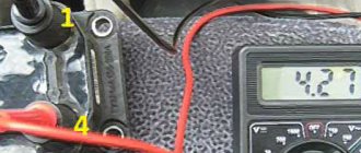
To check high-voltage wires with a multimeter, you will need to disconnect one line on both sides and attach probes to it on both sides. The resistance should be on high-voltage wires in the range from 0 to 9.8 kOhm. A difference of 2-4 units is not considered critical.
Spark plug diagnostics
In the event of a high-voltage breakdown, there is a possibility of failure of these batteries. During operation, the spark gap increases, so it is necessary to periodically perform diagnostics. For normal operation, the resistance at the spark plugs should be no more than 10 kOhm.
Wire check
To check, you can use available means, for example, a regular cable whose insulation is stripped on both sides. One end should be shorted to the car body (“to ground”), and the other should be moved along the cable in search of the place where the spark will “jump out.” It is also necessary to check the caps and the conductor. If there is a large difference in resistance or another malfunction is detected, it is necessary to replace the entire set of high-voltage wires.
Conductor design
There are several design options for the high-voltage ignition wire, which differ primarily in the design of the current-carrying element.
The first to use high-voltage wires with stranded cores. The latter consists of several, usually seven thin copper wires, twisted together in the form of a rope to provide the necessary mechanical stability under bending influences. An additional advantage of using a multi-wire structure is the improvement in the vibration parameters of the cable. The linear resistance of such a cable is hundredths of an ohm per meter of length.
The second option is based on a flexible dielectric core made of ordinary or Kevlar threads with additional impregnation, which is equipped with a thin copper braid. A ferroplastic film is sometimes used for the separating layer, the presence of which dampens parasitic high-frequency vibrations. Such products have an average linear resistance of about one to two kOhm/m.
High-resistance high-voltage wires with a linear resistance in the range of 10 - 40 kOhm/m have a flexible conductive core made of natural or artificial threads impregnated or with graphite additives. To impart mechanical strength, additional flexible dielectric reinforcing elements are introduced into the core structure.
GENERAL INFORMATION AND FEATURES OF GDP DESIGN
Unlike the rest of the car's wiring, high-voltage ignition wires have a rather complex design. They consist of plastic caps, metal contacts, an insulating layer and a copper conductor.
GDP insulation can be either single-layer or multi-layer, depending on the quality and cost of the wire. As a rule, all products from leading manufacturers have multi-layer insulation. The protective layer of GDP performs two main functions:
- Acts as a barrier that prevents current leakage;
- Performs the function of protecting the conductor from mechanical damage and aggressive environmental influences: fumes, fuels and lubricants, moisture, low and high temperatures.
The conductive core of the GDP is made of copper, since this material has minimal resistance and durability (about 8 years of operation). The conductive element of the GDP, according to GOST 14867-79, must meet the following requirements:
- Limit permissible voltage – 22 kV;
- Minimum breakdown voltage – 40 kV;
- Maximum electrical capacity – 100 pF/m;
At both ends of the wire there are metal tips that act as contacts, through which the VVP are connected to the coil and spark plugs.
Various types of explosive wire lugs
When purchasing, it is worth checking the high-voltage wires for the quality of the connection between the contacts and the core; it is necessary that they are firmly attached to the core and tightly connected to the spark plugs, since the lack of normal contact is one of the most common problems with VVP.
Plastic caps perform a protective function. They prevent moisture and dust from entering the contacts, and protect them from changes in ambient temperature.
Additional items
The purpose of the additional elements is to ensure ease of routine operation of the high-voltage cable. They are represented by copper lugs and protective caps, which are placed on both ends of the cable. The lug is the cable part of the detachable connector. A rubber or silicone cap blocks direct access to the metal and increases the breakdown resistance of the product by preventing dirt from entering the contact.
The cable with such elements installed on it turns into an easy-to-use cord that connects to the distributor and spark plugs with a simple linear movement.
Feature of connecting wires with low and medium linear resistance
To protect the high-voltage part of the ignition system, a ballast resistor is connected in series with the wire, which has low and medium linear resistance. Its function is to limit the maximum current flowing through the cable at the moment of spark discharge of the spark plug.
The resistance of the resistor is calculated in such a way that, given the small current values characteristic of the secondary winding that are supplied to the spark plug, the voltage drop across it during normal operation is small. Thus, the presence of this additional component does not affect the functioning of the ignition system. In case of insulation breakdown, short circuit and other faults, the current cannot increase noticeably due to its limitation by a resistor, which reliably protects the remaining elements.
The resistor can be located in different places in the circuit. Changing its location does not affect the efficiency of its functioning.
How to check high voltage ignition wires?
Checking high-voltage ignition wires for breakdown is carried out in one of three ways.
Visual inspection is the easiest way to check and detect damage to the insulating layer of high-voltage wiring. During this check, you need to make sure that there are no cracks, cuts or noticeable abrasions on the insulation surface. A breakdown can be visually determined by sparking. To do this, in the dark, just open the hood of the car, start the engine and turn off the lights. An insulation breakdown will be noticeable to the naked eye by sparks running through the wiring.
It is often impossible to visually determine that the high-voltage ignition wire is faulty. In such cases, the old proven method is used, which consists of the following steps. The engine is started and left to idle. Next, the contacts are removed one by one from the spark plugs and then put back on. All operations must be performed with rubber gloves, without touching the car body with your body. The conductor is faulty if, when it is disconnected from the spark plug, engine operation does not change.
The next method is to use a piece of wire stripped at both ends. The check is carried out at night with the engine running. One end of the segment is connected to the car body (“ground”), the other end must be driven along the high-voltage ignition wiring. If a spark appears when carrying out insulation, there is a breakdown in this place. This way, not only the insulation is checked, but also the plastic protective caps.
Checking high-voltage ignition wires with a multimeter
Car owners usually measure voltage with a multimeter, but the same device can also determine resistance, which is very useful when checking. To measure, high-voltage ignition wires are first disconnected or completely removed. The multimeter needs to be switched to resistance measurement mode, then the probes of the device need to touch the two ends of one wire. The device will show the measured value.
If, as a result of the test, one conductor turns out to be faulty, the rest will soon fail. Therefore, replacing the high-voltage ignition wiring is done as a set, rather than as separate wires. These products most likely will not be sold to you separately.
3 Tips for Selecting High Voltage Ignition Wires
Tip #1.
Carefully study the information about the product (manufacturer, terms of use, etc.) - it should be available both on the packaging and on the product itself.
Often, on fakes, the English word “silicone” is misspelled. This phenomenon is so widespread that it was even found in one authoritative print media on automotive topics. The authors mistakenly and without verification used the word “silicon,” which actually translates as “silicon.”
Tip #2.
Evaluate the quality of caps on high-voltage electrics.
The caps are made of silicone rubber; they are necessary to protect the wiring contacts and ensure the tightness of the connections. The minimum wall thickness of the cap is 3 mm. As inspection often shows, the electrical circuit is broken precisely at the junction of the conductor terminal with the contacts of the ignition system elements. This usually happens when the wiring is removed inaccurately or when there is a poor connection with parts of the ignition system due to poor fit, oxidation processes, etc.
Tip #3.
Evaluate the quality of the highest voltage ignition wiring.
Silicone products are of the best quality today. There are several simple ways to check their quality. For example, you can expose the cable to open fire. If the insulation is of high quality, it will not be easy to melt or even ignite it. Another way to check is to twist the wire tightly. If displacement or sliding of the core relative to the cable sheath is felt, and a characteristic crunching sound occurs, it means that the adhesion of the sheath to the insulation is poor. Also try moving the insulation layer along the conductor. There should be no displacements during testing; the cable must be solid. Otherwise, when installing or dismantling the wiring, the protection may be impaired.
Useful materials about cars
here!
Source

