Injectors for VAZ 2110–2112 cars
Cars of the “tenth” family are equipped with various injection engines, each of which is designed to work with a specific model of injectors. Despite the fact that they have their own “names,” motorists usually use a “folk” classification based on color and thickness. For example: black thin ones.
This simplification usually works, but does not fully guarantee the compatibility of the injector with the engine. To avoid having to contact the chip tuner once again to correct the firmware of the electronic injection control unit, check the part number before purchasing.
Table: compatibility of injectors and engines of VAZ 2110–2112 cars
| Engine | Volume (l) | Number of valves | Controller (ECU) | Firmware | Injectors | |
| Siemens | Bosch | |||||
| VAZ-2111 | 1,5 | 8 | M1.5.4 | January-5.1 | VAZ6238 (thick gray) | 0 280 150 996 (turquoise thick) |
| VAZ-2111 | 1,5 | 8 | M7.9.7 | January-7.2 | VAZ6393 (beige thick) | 0 280 158 502 (black thin) |
| VAZ-21114 | 1,6 | 8 | M7.9.7 | January-7.2 | VAZ20734 (orange thin) VAZ20734 (yellow thick) | 0 280 158 017 (black thin) |
| VAZ-2112 | 1,5 | 16 | M1.5.4 | January-5.1 | VAZ6238 (thick gray) | 0 280 150 996 (turquoise thick) |
| VAZ-21124 | 1,6 | 16 | M7.9.7 | January-7.2 | VAZ20735 (blue thin) VAZ20735 (pink thick) | 0 280 158 022 (black thin) |
Photo gallery: injectors for VAZ 2110–2112 cars
Differences between injectors for eight and sixteen valve engines
Among some motorists there is an opinion that the injectors for the “ten” differ depending on the number of engine valves. Others believe that the determining factor is the volume of the cylinders.
Clogged injectors can cause the car to jerk when driving. Details: https://vazweb.ru/desyatka/pitanie/dergaetsya-pri-dvizhenii.html
In reality, neither one nor the other is wrong. The parts must match the engine design, model and firmware of the electronic control unit.
When replacing, it is best to install the same ones that were installed previously. Otherwise, there may be difficulties with startup and operation in transient conditions. To eliminate the shortcomings, you will have to adjust the firmware, which is almost impossible in a garage environment.
In-cylinder fuel injection has been known since the very dawn of the automobile industry. In the early 1890s, the German Rudolf Diesel and the Englishman Herbert Ackroyd-Stewart secured the rights to their own designs for an internal combustion engine running on fuel oil.
Vladimir Bekrenev
bvy.su
Causes of unstable engine operation
When a VAZ 2110 engine with an 8-valve injector malfunctions, the reasons are sought in a certain sequence.
Systems and individual components are checked:
Electrics
When the engine of a VAZ 2110 8-valve injector malfunctions, the reasons, first of all, should be sought in the electrics.
Only after this is it possible to establish unstable operation of the cylinder. First, the candles are inspected:
When the VAZ 2110 engine has trouble with the 8-valve injector, the reasons may lie in the high-voltage wires. To do this, a tester is used that checks them for resistance, the optimal value of which is 5 ohms. If the wires do not meet this specification, they need to be replaced.
There is also a lack of spark due to the following reasons:
The spark plug operation is checked in the following sequence:
Cylinder operation
If the VAZ 21108 engine has 8 valve injector valves, then a possible cause may be poor cylinder performance.
When it is determined that everything is in order with the electrical part, the following actions are carried out:
Knowing that the voltage is coming through the wire, a search is being carried out for another reason why the VAZ 2110 engine is having problems with the 8-valve injector.
Ignition
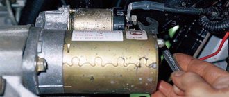
VAZ 2110 engine 8 valves, the injector may trip if the coil is faulty.
To check, the following steps are carried out:
If 1 of these indicators is not met, this will be the reason why the VAZ 2110 8-valve engine has an injector problem.
Depressurization of the system and air leaks
If the VAZ 2110 engine has trouble, the cause of the malfunction may lie in excess air supply.
As a result of depressurization, uncontrolled suction occurs, which leads to disruption of the functioning of the system. To check for a leak, carry out the following steps:
Insufficient amount of air in the combustible mixture
If there is a lack of air in the combustible mixture, the VAZ 2110 8-valve engine and 8-valve injector may also begin to stall.
The following problems exist:
Fuel injectors
VAZ 2110 engine 8 valves, the injector may triple due to a malfunction of the injectors, as well as the fuel rail.
To understand how faulty the injectors are, a stand is used that provides complete information about them. In some cases, they need cleaning, which is also carried out at the stand. The ramp is also subjected to external examination for cracks or dents.
Pistons and rings
A malfunction in the piston system often leads to the fact that the VAZ 2110 engine begins to misfire.
It depends on the mileage traveled by the car. Unstable operation occurs for the following reasons:
These reasons lead to a decrease in compression. It is checked by adding oil to the cylinder. If its performance has increased, then the piston group requires replacement.
Sensors
If sensors fail, this affects the unstable operation of the car. This is due to the fact that the nodes send a signal to the electronic unit. If it is absent, the receipt of commands to control the machine stops.
To identify a malfunction, each sensor is checked individually until the faulty element is found.
Repair
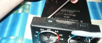
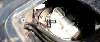
Before removing the injectors from the dismantled rack, it is advisable to check their functionality. To check you will need:
- four identical containers,
- tester,
- wires.
Functionality check
- Connect the gasoline supply and drain hoses and the power connector to the rail with injectors.
- Place the rack over the measuring cups.
Place the rack over the measuring cups
The shape of the cloud should be approximately the same for all nozzles
After the war, Germany received a ban on the development of injectors for aircraft engines. And engineers began adapting direct injection systems for passenger cars, discovering another important advantage compared to carburetors - efficiency.
Vladimir Berestenev
bvy.su
Replacement or flushing?
Some problems can be eliminated by cleaning and flushing. Others are “treated” only by replacement.
Table: problems with injectors
| Malfunction | Remedy |
| reduced performance | flushing, replacement if flushing fails |
| leakage | flushing, replacement if flushing fails |
| increased productivity | replacement |
| valve sticking | replacement |
| unstable valve sticking | flushing, replacement if flushing fails |
| overestimated or underestimated winding resistance | replacement |
In these cases, flushing is not a panacea. This method should be used taking into account the mileage and quality of service during operation.
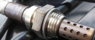
During operation, the injector nozzles inevitably become coked and clogged with resinous deposits. The picture is aggravated by low-quality fuel, which can introduce additional pollutants.
For some time, fuel atomizers continue to operate without any visible changes, but sooner or later contaminants accumulate, changing the shape of the spray and reducing performance.
Injector life expectancy is limited even when using the cleanest fuel. Manufacturers recommend changing them every 100–120 thousand kilometers. Due to the fact that motorists use imperfect gasoline, and the one that can be bought at gas stations, the part has to be changed after 80-100 thousand km.
There is an opinion among motorists that “there is no need to interfere if everything works fine.” This opinion is justified, but only if the owner is ready to replace the nozzles with new ones approximately every 50 thousand kilometers.
The fact is that by getting rid of minor deposits as they accumulate, the owner extends the life of the consumable, since pollutants do not have time to cause irreparable damage.
Clogged injectors begin to interfere with normal operation after 30–50 thousand km. Initially, negative processes manifest themselves only in increased fuel consumption. Owners do not always associate the increased “appetite” of the engine with injectors, since there are many reasons for this phenomenon.
In the range of 50–80 thousand km, pollution, having accumulated, can cause interruptions in engine operation, which is no longer undetectable. It becomes clear that “you have to get into the injectors,” but cleaning them at this stage may be useless. When a clogged part is used for a long time, the diameter of the nozzle often increases. Flushing will remove contaminants, but the original parameters will not be restored.
To extend the life of trouble-free operation and delay replacement, you should regularly, after approximately 3-5 thousand kilometers, fill the tank with cleaning fluid for injectors or use it in another way recommended by the manufacturer.
Motorists' opinions about the effectiveness and safety of injection chemicals are contradictory. Many people fear that flushing without removing it from the engine will clog the cylinders.
Indeed, if the car owner has not touched the injectors for a long time, it is impossible to do without removing the rack. The chemicals in the tank can cause harm instead of benefit. If you use cleaners regularly, without waiting for characteristic malfunctions to appear, there will be no harm to the engine from the chemicals.
Although injection chemistry has a beneficial effect on slightly dirty injectors, its use does not guarantee that the atomizers will comfortably “live” the entire period “allotted” to them by the manufacturer. You can unsuccessfully fill the tank with “left” gasoline at almost any gas station.
To minimize the accumulation of deposits, manufacturers recommend additional preventive flushing with special products every 30 thousand kilometers.
Table: advisability of flushing and replacement depending on mileage
| Mileage (thousand km) | Flushing | Replacement |
| up to 30 | preventive flushing with fuel additives every 3–5 thousand km | individual replacement of faulty parts |
| 30–80 | preventive flushing with a special agent every 30 thousand km | individual replacement |
| 80–120 | preventive flushing with a special agent every 30 thousand km | complete replacement of all injectors if at least one faulty one is detected |
Flushing without removing from the engine
At the first sign of clogged injectors, repairs should not be put off for a long time, as delay only aggravates the situation. You can turn to professionals for help, but you can also wash it yourself.
To assemble a homemade device and wash them, you will need:
- flushing liquid - 1 l;
- plastic bottle with cap;
- fine fuel filter;
- rubber hose with a diameter of 12 mm - 1 m;
- clamp 12–14 mm - 2 pcs.;
- nipple assembly (fungus) - 2 pcs.;
- foot or electric pump with pressure gauge.
- Drill holes in the bottom and cap of the bottle and install nipples in them.
Drill holes in the bottom and cap of the bottle and install nipples in them
Connect the bottle cap nipple and the fuel filter with a hose.
Attach the filter output of a homemade flushing device to the fuel rail inlet fitting
In a similar way, you can wash the fuel rail assembly removed from the engine without dismantling the injectors.
Washing removed from the engine
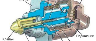
To wash an injector removed from the engine, it is necessary to create increased pressure of the cleaning liquid at its inlet, and then periodically turn the solenoid valve on and off, simulating the operation of the car’s electronic control unit.
Increased pressure can be easily created using carburetor cleaner in an aerosol can. In addition to this, you will need:
- DC voltage source 12 V,
- wires,
- non-latching button,
- terminals for connecting to the injector,
- disposable syringe 5 ml,
- cambric (plastic tube) for connecting the syringe and the spray can,
- container for collecting flushing liquid.
- Remove the plunger from the syringe. Connect the nozzle of the syringe and the nozzle of the aerosol can with a cambric. Secure the connection with wire or tape.
- Connect the nozzle to the power source via the button.
- Place the wide end of the syringe onto the inlet of the nozzle.
Place the wide end of the syringe onto the nozzle inlet
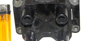
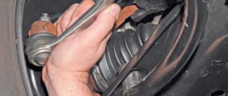
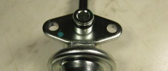
Replacing O-rings
To prevent fuel leakage, do not reuse the O-rings of the injector and injector body. They are replaced with new ones every time they are removed for any reason.
To remove the old ring, just pry it up with a screwdriver. When installing new ones, do not use hard tools; install the seals by hand. Before installing the injector, lubricate the rubber bands with engine oil.
To remove the old ring, just pry it up with a screwdriver
An injection engine is not at all complicated, as owners of carburetor cars sometimes believe. Injectors are reliable parts that require only a little attention. Show it, and the engine will thank you.
Source
Technical features of the VAZ-2111 8 valve injector and its engine
All modifications of the VAZ-2110 have a number of standard features that distinguish these cars from other vehicles of this type. Let's look at them:
- Engine location is front.
- The drive also falls on the front wheels.
- The body of the supporting structure is all-metal.
- Body type – station wagon.
- Four-cylinder, four-stroke, 8- or 16-valve gasoline engine.
- The power system is carburetor or with distributed fuel injection.
The VAZ-2111 engine is equipped with a power system that has distributed fuel injection, and it is controlled by one of the controllers - January, Bosh, GM.
But any similar design used on the VAZ-2111 must meet the following requirements:
- petrol;
- 4-stroke;
- 4-cylinder;
- in-line (transverse arrangement);
- 8-valve;
- The camshaft is located at the top.
This model is a modernized version of the VAZ-2110 engine, which is of the carburetor type. The modernization was carried out in order to smoothly transfer to another power system - injection. Thus, four cylinders are made of cast iron, and the connecting rods have a more massive lower part, which makes it possible to increase the service life to 250 thousand kilometers in real conditions, although the manufacturer assumes 150 thousand kilometers. By the way, when carrying out repair operations, the nominal diameter of a cast iron cylinder of 82 millimeters can be increased from 0.4 to 0.8 millimeters. But at the same time, one should take into account the maximum limit of its permissible wear - 0.15 mm per diameter. The crankshaft is also made of high strength cast iron. Special inserts are produced for it, intended for repair, which are specially reduced to 1 millimeter. On the VAZ-2111, the engine is included in the power unit, which also includes a clutch and gearbox. This unit is a unit of a single type that is mounted in the engine compartment using rubber-metal elastic supports.
Standard and major repair work: VAZ-2111 engine (8 valve injector)
Standard (typical) engine repair work on any vehicle is often needed not only when the car stops working. Depending on the indications, they may include the following operations:
- Replacement of components:
- valve lifters;
- oil deflector valve caps;
- timing belt;
- camshaft oil seal.
- Disassembly:
- cylinder heads;
- oil pump.
- Removal and subsequent replacement:
- lamp sensor that controls oil pressure;
- low oil level sensor;
- rear support of the power unit;
- manifolds – intake and exhaust;
- housings of auxiliary units;
- oil receiver;
- power unit supports;
- oil pan;
- camshaft;
- receiver and collectors.
- Adjustment:
- thermal clearances in the valve mechanism.
- Dismantling the ShPG (connecting rod and piston group).
Experts also include removing the engine from the vehicle as repair work. But this procedure is carried out already at the moment when the car needs major repairs. By major repair work related to the VAZ-2111 engine, experts mean the following operations:
- Complete disassembly.
- Diagnostics.
- Direct repair.
- Metalworking of those elements that need it (for example, grinding a crankshaft or milling a cylinder head).
- Replacement of parts that have failed.
If you decide to repair the VAZ-2111 engine yourself, without turning to qualified auto repair specialists, then the book “Operation, Maintenance and Repair Manual: VAZ-2110, VAZ-2111, VAZ-2112” from the “Do It Yourself” series will be a good help " This manual was written by a team of authors and published in 2012. Summary:
- a detailed description of the designs of components and systems of the listed passenger car models;
- the main faults are characterized;
- causes of breakdowns and malfunctions in the functioning of the engine;
- DIY troubleshooting methods;
- Applications are posted with a list of necessary materials for current and major repair work (for example, lubricants, operating fluids), tools.
In addition to clear and intelligible technological instructions, it contains 15 electrical circuits, as well as photographs with comments.
engine malfunctions of VAZ 2110 cars | VAZ 2111 | VAZ 2112
On cars of the VAZ 2110 family, engines of models 2110, 2111 and 2112 are installed. Some of the cars produced can be equipped with 21083 engines, a description of the repair of which can be found in the Repair Manual for VAZ 2108, VAZ 2109 cars. Section 2 describes the repair of the 2110 engine, and Features of repair of engines 2111 and 2112 are given in section 9. Engine 2110 (Fig. 2-1 and 2-2) is a four-stroke, carburetor, four-cylinder, with an in-line vertical arrangement of cylinders and an overhead camshaft. The engine is designed on the basis of the 21083 engine. Therefore, its layout, main dimensions and many components and parts are the same as those of the 21083 engine. The units and components of the VAZ 2110, VAZ 2111 and VAZ 2112 engines are given here:-
rice. 2-1. lengthwise cut
rice. 2-2. cross section of possible engine malfunctions of VAZ 2110, VAZ 2111, VAZ 2112 cars, their causes and methods of elimination
| cause of malfunction | elimination method |
| the engine does not start | |
| 1. There is no fuel in the carburetor: the fuel lines or fuel filter are clogged; the carburetor and fuel pump filters are clogged; malfunction of the fuel pump 2. The carburetor solenoid valve does not open when the ignition is turned on: a break in the wires going to the valve control unit and the valve; the solenoid valve control unit is faulty; the solenoid valve is faulty 3. The carburetor starting device is faulty 4. The ignition system is faulty | 1. Do the following: blow out the fuel lines, wash the fuel tank, replace the fuel filter; wash the filters; check the operation of the pump and replace damaged parts 2. Do the following: check the wires and their connections, replace damaged wires; replace the control unit; replace valve 3. Replace damaged parts of starting device 4. See subsection “ignition system” |
| The engine runs rough or stalls at idle | |
| 1. The engine idle speed adjustment is faulty 2. The carburetor solenoid valve control system is faulty 3. The carburetor is faulty: the carburetor jets or channels are clogged; water in the carburetor; the tightness of the diaphragm of the starting device is broken 4. Air leakage through a damaged hose connecting the intake pipe to the vacuum brake booster 5. Air leakage through gaskets in the connections of the intake pipe with the carburetor or with the cylinder head 6. Air leakage through damaged vacuum sampling tubes to the heater electro-pneumatic valve or to the sensor -ignition distributor 7. The ignition system is faulty | 1. Adjust idle speed 2. See “engine does not start” fault 3. Do the following: blow out the carburetor jets and channels; remove water from the carburetor, drain sediment from the fuel tank; replace diaphragm 4. Replace damaged hose 5. Tighten the fastening nuts or replace the gaskets; eliminate deformation of the carburetor flange or replace the carburetor 6. Replace damaged tubes 7. See subsection “ignition system” |
| the engine does not develop full power and does not have sufficient throttle response | |
| 1. Incomplete opening of the carburetor throttle valves 2. The air filter element is dirty 3. The ignition system is faulty 4. The fuel pump is faulty 5. The carburetor is faulty: the accelerator pump is faulty; the main jets are clogged; the air damper is not fully open; the fuel level in the float chamber is not normal; the tightness of the economizer diaphragm of power modes is broken 6. The ventilation tube of the fuel tank is clogged 7. The clearances in the valve mechanism are broken 8. The timing marks of the gas distribution phases do not match 9. Insufficient compression - below 1 MPa (10 kgf/cm2): breakage or jamming of the piston rings; poor fit of valves to seats; Excessive wear on cylinders and piston rings | 1. Adjust the throttle valve drive 2. Replace the filter element 3. See the subsection “ignition system” 4. Check the operation of the pump and replace damaged parts 5. Do the following: check the pump supply, replace damaged parts, blow out the jets with compressed air; adjust or repair the automatic carburetor starter; adjust the float setting; replace the diaphragm 6. Blow the tube with compressed air 7. Adjust the gaps 8. Rearrange the timing belt, aligning the installation marks 9. Do the following: clean the rings and piston grooves from carbon deposits, replace damaged parts; replace damaged valves, polish seats; replace pistons, bore and hone cylinders |
| knocking of the main bearings of the crankshaft. Usually this knock is dull, metallic. It is detected when the throttle valves are opened sharply at idle. Its frequency increases with increasing crankshaft speed. Excessive axial clearance of the crankshaft causes a sharper knock, with uneven intervals, especially noticeable when the crankshaft rotation speed is gradually increased and decreased. | |
| 1. Ignition too early 2. Insufficient oil pressure 3. Loose flywheel mounting bolts 4. Increased clearance between journals and main bearing shells 5. Increased clearance between thrust half rings and crankshaft | 1. Adjust the ignition timing 2. See the fault “insufficient oil pressure at idle” 3. Tighten the bolts to the recommended torque 4. Grind the journals and replace the bearings 5. Replace the thrust half-rings with new ones, check the gap |
| knocking of connecting rod bearings Usually the knocking of connecting rod bearings is sharper than the knocking of the main bearings. It can be heard when the engine is idling when the throttle valves are opened sharply. The location of the knock can be easily determined by turning off the spark plugs one by one. | |
| 1. Insufficient oil pressure 2. Excessive clearance between crankshaft crankpins and bearings | 1. See the fault “insufficient oil pressure at idle” 2. Replace the bearings and grind the journals |
| knocking of pistons This knock is usually quiet, muffled; it is caused by the “beating” of the piston in the cylinder. It is best heard at low engine speeds and under load. | |
| 1. Increased clearance between pistons and cylinders 2. Excessive clearance between piston rings and grooves on the piston | 1. Replace pistons, bore and hone cylinders 2. Replace rings or pistons with rings |
| knocking of intake and exhaust valves Increased clearances in the valve mechanism cause a characteristic knocking sound, usually at regular intervals; its frequency is less than the frequency of any other knock in the engine, since the valves are driven by the camshaft, the rotation speed of which is half the speed of the crankshaft. | |
| 1. Increased clearances in the valve mechanism 2. Broken valve spring 3. Excessive clearance between valve and guide sleeve 4. Worn camshaft cams | 1. Adjust clearances 2. Replace spring 3. Replace worn parts 4. Replace camshaft and shims |
| insufficient oil pressure at idle on a warm engine | |
| 1. Foreign particles getting under the oil pressure reducing valve 2. Sticking of the oil pressure reducing valve 3. Worn oil pump gears 4. Excessive clearance between the bearings and main journals of the crankshaft 5. Excessive clearance between the journals and camshaft bearing housings 6. Use of engine oil inappropriate brand and quality | 1. Clean the valve from foreign particles and burrs, wash the oil pump 2. Replace the valve 3. Repair the oil pump 4. Grind the journals and replace the bearings 5. Replace the camshaft or cylinder head with bearing housings 6. Replace the oil with another one recommended in Appendix 4 |
| Excessive oil pressure on a warm engine | |
| 1. The oil pressure reducing valve is stuck 2. The oil pressure reducing valve spring is too stiff | 1. Replace valve 2. Replace spring |
| increased oil consumption | |
| 1. Oil leakage through the engine seals 2. Clogged crankcase ventilation system 3. Wear on the piston rings or engine cylinders 4. Broken piston rings 5. Coking of the slots in the oil scraper rings or grooves in the piston grooves due to the use of non-recommended oil 6. Wear or damage valve seals 7. Increased wear of valve stems or guide bushings | 1. Tighten the fasteners or replace the gaskets and seals 2. Wash the crankcase ventilation system parts 3. Bore the cylinders and replace the pistons and rings 4. Replace the rings 5. Clean the slots and grooves from carbon deposits, replace the engine oil with the one recommended in Appendix 4 6. Replace oil seals 7. Replace valves, repair cylinder head |
| increased fuel consumption | |
| 1. The carburetor air damper is not fully open 2. Increased resistance to vehicle movement 3. Incorrect ignition timing setting 4. The vacuum regulator of the ignition distributor is faulty 5. High fuel level in the carburetor: the tightness of the needle valve or its gasket is broken; jamming or increased friction that prevents the normal movement of the floats 6. The carburetor air jets are clogged 7. The seal of the economizer diaphragm of the carburetor power modes is broken 8. The carburetor solenoid valve does not shut off the fuel supply during forced idle speed: the moving contact of the limit switch does not close to ground; a break in the wire connecting the control unit to the carburetor limit switch; control unit is faulty | 1. Adjust the automatic carburetor starter 2. Check and adjust the tire pressure, brake system, wheel alignment angles 3. Adjust the ignition timing 4. Replace the vacuum regulator or ignition distributor 5. Do the following: make sure there are no foreign particles between the needle and valve seat, replace the valve or gasket if necessary; check and replace floats if necessary 6. Clean the jets 7. Replace the diaphragm 8. Do the following: clean the contact surfaces of the switch; check the wire and its connections; replace the damaged wire; replace the control unit |
| engine overheating The coolant temperature gauge needle is in the red zone of the scale. Before troubleshooting, make sure that the coolant temperature indicator and its sensor are in working order (see subsection “Control devices”). | |
| 1. Insufficient amount of liquid in the cooling system 2. Incorrect ignition timing 3. The outer surface of the radiator is very dirty 4. The thermostat is faulty 5. The fan motor does not work 6. The coolant pump is faulty | 1. Add coolant to the cooling system 2. Adjust the ignition timing 3. Clean the outer surface of the radiator with a jet of water 4. Replace the thermostat 5. Check the electric motor, its sensor and relay; replace faulty components 6. Check the operation of the pump, replace it or repair it |
| rapid drop in fluid level in the expansion tank | |
| 1. Damaged radiator 2. Damage to hoses or gaskets in pipeline connections, loose clamps 3. Leakage of liquid from the faucet or heater radiator 4. Leakage of liquid through the coolant pump seal 5. Damaged cylinder head gasket 6. Leakage of liquid through microcracks in the block or in cylinder head 7. Liquid leakage through microcracks in the coolant pump housing, in the outlet pipe of the cooling jacket, in the thermostat, expansion tank or inlet pipe 8. Deformation of the coolant pump supply pipe flange 9. Low opening pressure of the expansion tank plug valve | 1. Repair or replace the radiator 2. Replace damaged hoses or gaskets, tighten hose clamps 3. Replace the faucet or radiator 4. Replace the oil seal 5. Replace the gasket 6. Check the tightness of the block and cylinder head, if cracks are found, replace damaged parts 7. Check the tightness, if cracks are found, replace damaged parts; a minor leak can be eliminated by adding a sealant type NIISS-1 to the coolant 8. Replace the supply pipe 9. Check the plug and replace if necessary |
- Author: admin
Rate this article: Share with friends!
engine malfunctions of VAZ 2108, VAZ 2111-80, causes and methods of troubleshooting
engine power supply systems for VAZ 2110 cars | VAZ 2111 | VAZ 2112
Why do you need routine and major engine repairs?
As already mentioned, current repair work should be understood as the procedure for disassembling and assembling a vehicle engine with the subsequent replacement of some parts. Most often, replacements and upgrades require components such as:
- liners - main and connecting rod;
- piston rings;
- valve seals.
These replacements are a necessity, albeit periodic. They will not only increase engine resources, but also change the quality of its operation.
Experts consider routine repairs to be a temporary measure, and sooner or later the entire power unit of the vehicle may fail. Therefore, major repair work makes it possible to:
- Extend the service life of the engine.
- Prevent malfunctions in its functioning and failure.
- Will raise the level of resourcefulness.
- Will improve the overall performance of the vehicle.
Of course, it is best to entrust engine repairs and maintenance to knowledgeable and qualified auto service technicians.
Why is the VAZ-2110 electrical circuit needed?
When replacing or repairing an injector with 8 valves, the electrical diagram serves as a kind of guide, with the help of which you can understand all the nuances in the process of connecting specific wiring parts. In addition, the VAZ-2110 electrical diagram when using an injector with 8 valves allows you to understand the functioning of all electrical wiring devices.
In the diagram, the injector valves are evenly spaced, while the system itself is presented in the form of two combined components:
- Fuel distributor;
- Electrical equipment for the ignition control system.
Also, the diagram with 8 and 16 valves indicates the location of the electronic unit, with the help of which the operation of the above two systems is coordinated. Backup equipment, in turn, protects electrical wiring from overloads and increases the operating efficiency of the entire injection system.
Advice: if you are going to repair the injector, be sure to look at the wiring diagram for the VAZ-2106. This will give you the opportunity to replace any faulty parts without affecting the overall functioning of the vehicle's wiring.
The elements indicated by numbers in the diagram are shown below:
The diagram of electrical wires and fuses gives an understanding of the entire operation of the injection system, and also shows the specific position of each of the elements. It contains the following elements:
- Central nozzle. Acts as a distributor of fuel supply to the system. There is also a special type of fuel regulator that works as a sensor and ensures that the fuel supply does not go beyond the normal limits.
- Diaphragm regulator. Monitors fuel pressure in the ignition system and removes excess fuel back into the tank body.
Advice: make sure that the pressure in the fuel supply system does not exceed 300 MPa. Otherwise, you will see the corresponding icon on the instrument panel and you will most likely have to replace the coolant on the VAZ-2110.
- Bypass valve design. It regulates the position of the cross diaphragm, which is subject to constant pressure from three sides: on one side, the pressure of the fuel itself, on the other side, the tangential load from the intake air volumes, and on the 3rd side, the tension from the spring attached to the valve.
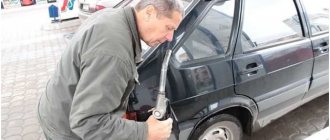
Diagnostics of the VAZ-2110 injector
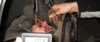
Diagnostics: connect its wire block to the harness connector, and then the ground wire to the battery; lower the injectors into containers with transparent walls, and then check the atomization of gasoline - turn on the starter. The fuel must be sprayed in the correct cone, 4 jets must shoot out from all nozzles, the amount of sprayed fuel must be the same in all 4 containers (checked with a measuring container).
An injector that does not meet these requirements must be replaced.
Turn off the ignition and inspect the injector: if fuel is noticeably leaking from any nozzle, this nozzle is leaking and must be replaced. If the fuel does not spray at all, then check the power supply: disconnect the connector with the wires (after disconnecting the battery) and connect the battery directly, observing the polarity, to the injector contacts, and then turn on the ignition - if the injector starts to spray, then its electrical circuit is faulty.
We check the resistance of the windings: disconnect the plug with wires from the injector (after disconnecting the battery) and connect an ohmmeter to its contacts. The device readings should correspond to 11–15 Ohms. If they differ, then the injector should be changed.
Home → Device → Fuel and exhaust systems → Fuel injection system → Contents
How to adjust the fuel supply process using an electrical circuit?
According to the scheme described above, fuel regulation in a car is carried out. Moreover, it depends not only on the load of the valves in the engine, but also on the corresponding position relative to the throttle valve. With the help of a diagram of electrical wiring and valves, it is possible to understand which of the relays or fuses is malfunctioning and replace it in time. In this case, one of the main roles when supplying fuel is played by electrical equipment (controllers) that regulates the operation of the injector.
How does the controller monitor the operation of the injector?
When determining the specific position and opening time of the injector design, the specific volume of fuel entering the valves of the VAZ-2110 cylinder is determined. At the same time, thanks to special sensors installed on the motor, the on-board computer records specific values and transmits them to the controller.
Subsequently, the controller, based on the information coming from the on-board computer, makes a decision on the position and duration of opening of the injector damper. If the controller malfunctions, the injectors will not be adjusted correctly, and the engine may stall while driving.
Tip: when starting the engine, the injector controller operates in asynchronous mode until the engine reaches a certain number of revolutions. That is why, after replacing the silent blocks of the front control arms on a VAZ-2110, you should warm up the car for 10-15 minutes.
No spark
Another most common problem with the VAZ 2110 injector is a malfunction called “no spark.” It can occur for several reasons.
- The first is that the controller has flown (this applies to cars with an electronic ignition mechanism). Because of this, the engine is unable to produce a spark. You will have to buy a new controller, since it is very difficult to repair the part yourself. But by replacing the controller, you will get rid of the problem and bring your engine back to life.
- The spark plug has failed. To find out for sure whether this is so, you need to replace the old spark plug with a new one, which it is advisable to always keep in the glove compartment, and look. If the engine starts, then the problem lies in the spark plug; if not, then you need to look further.
- Engine operation is often affected by defective spark plug wires, therefore, when checking the functionality of the spark plug, also check all the wires and ignition coils; there may be microscopic damage that prevents the engine from working.
We looked at the characteristics and most common malfunctions of the VAZ 2110 injection engine. Now you know what to do when the spark suddenly disappears, when the injectors become clogged or the fuel mixture becomes lean. Knowing the theoretical side of these issues, over time you can master them in practice. Good luck!
We recommend reading:
- VAZ 2110 fuse box diagram
- The engine of a VAZ 2110 is overheating and what should I do?
- Fuel pump relay for VAZ 2110
- When a VAZ 2110 car starts and then stalls: our actions
- Firmware methods for VAZ 2110
- The procedure for replacing engine mounts on a VAZ 2110
How does a malfunction of the electronic control unit affect the operation of the injector?
The electronic control unit of the VAZ-2110 car consists of 3 high-precision components:
- ROM – devices for storing data (memory);
- PROM – a device for transmitting dynamic data;
- RAM is the regulating memory of the block.
Advice: the entire complex of presented elements will function only if there is voltage in the circuit. If there is no voltage in the wiring, then it is necessary to eliminate the faults in the fuse box on the VAZ-2110.
Thus, the electronic control unit acts as a kind of microprocessor that is responsible for the operation of the entire fuel supply system. If it breaks down, even an experienced motorist cannot fix it with his own hands. For repairs, contact your nearest car service center and wait for the result. If the unit does not have any malfunctions, the breakdown must be looked for among the elements of the injector and controller.
Tip: in the center of the dashboard on a VAZ-2110 car, a warning light called “CHECK ENGINE” may light up. In this case, the problem definitely does not lie in the control unit, the problem is related to malfunctions in the controller.
So, if you notice that your engine begins to constantly stall while driving and spends more fuel at the same distance as before, refer to the injector diagram for the VAZ-2110. Having a little understanding of each of the elements, you can quickly find the faulty element and replace it.
Basic information about the injector circuit
Wiring diagram of VAZ 2110 injector 8 valves
The VAZ injection system is designed quite simply and contains practically no nuances specific to understanding. A novice motorist even knows the general principle of operation of injection systems. Elements of an injection system and their basic functions:
- the fuel regulator is located on the injector, the latter, in turn, is located on the frame to which fuel is supplied using a pump (all the fuel first passes through a specialized filter);
- the fuel pressure should not exceed 300 mPa, therefore, if any excess fuel occurs, it is sent back to the tank using a membrane regulator;
- the bypass valve controls the position of the diaphragm, which in turn is subject to triple pressure: the pressure of the fuel itself, as well as the intake air and the corresponding spring;
- the fuel regulation scheme described above directly depends not only on the current engine load, but also on the throttle position;
Wiring diagram of VAZ 2110 injector 8 valve
- the cylinder is filled with fuel during rotation of the crankshaft, the volume of incoming fuel is determined by the position of the injector (see VAZ 2110 injectors and their cleaning), which is directly controlled by the controller.
The role of the injector and controller in the overall injector circuit
- the position and opening time of the injector determines the volume of fuel that enters the cylinders;
- special sensors are installed on the engine that transmit relevant information to the controller;
- the controller, based on information received from the engine, sends an electrical pulse of a certain length, which determines the duration of opening of the injectors;
- when starting the engine, the controller is in asynchronous operating mode until the engine itself reaches 400 revolutions in one minute;
Wiring diagram of VAZ 2110 injector 16 valves
- injectors may temporarily not function in the event of braking or if the engine is in purge mode;
- if the engine operates in high load mode, then the throttle and air information sensors transmit the corresponding electrical impulse to the controller, which in turn sends the corresponding signal to the injectors taking into account the current speed of the vehicle;
- Thus, in the injector circuit, the controller is a regulating element, and the injectors are an executive element.
The role of the electronic control unit in the overall injector circuit
From a practical point of view, the electronic control unit consists of several high-tech components: ROM - memory devices, PROM - dynamic memory devices, RAM - regulatory memory (all of the above elements function only if there is voltage available).
Note. The electronic control unit is actually a microprocessor, so even an experienced motorist is simply not able to repair it, since specialized knowledge from the relevant higher school is required.
- all engine parameters, together with the microprocessor operating program, are stored in ROM;
- RAM is a random access memory, which is a temporary source of information storage, and each new start of the microprocessor leads to a complete clearing of intermediate information;
VAZ 2110 injector sensor diagram
- all information coming from the sensors to the controller is not only analyzed, but also stored; at the same time, the controller itself carries out diagnostics of the information sensors from time to time;
- Ignition and injectors are the main functional elements of the injection system, subordinate to the controller.
Note. There is a “CHECK ENGINE” warning light on the dashboard; if it lights up, it means that the controller is in a faulty state or there has been some malfunction in its operation.