Soviet grenade RGD-33
In the mid-twenties of the last century, the leadership of the Red Army faced the question of global rearmament of army units. Which meant the development of new types of weapons, or a deep modernization of old ones left over from the tsarist arsenals.
Such standard weapons of an ordinary soldier as grenades were not left without attention.
Therefore, from the mid-twenties, under the leadership of the Soviet designer Dyakonov, the development of a new model of “pocket artillery” began.
In 1926, the grenade was developed, then over the course of several years it was refined during field tests and, finally, in 1933 it was adopted by the Red Army under the designation RGD-33. Which was deciphered as a Dyakonov hand grenade, model 1933.
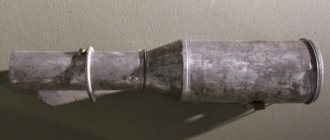
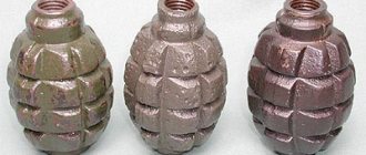
The grenade body was made of tin and had a cylindrical shape. A demolition charge was placed inside it - up to 140 grams of TNT. The body was closed at the top and bottom with tin lids. A hollow tube ran along its entire length in its center, into which the grenade fuse was installed.
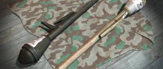
The fuse hole on top was closed with a valve. From below, the tube ended with a peg protruding 7-8 millimeters, onto which a locking nut was screwed, securing the bottom cover and the grenade handle itself. If necessary, a special shirt was put on the body of the grenade, which increased the number of fragments when the grenade exploded and turned it from offensive to defensive.
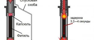
The fuse was a hollow copper tube with an igniter primer, a powder retarder, giving the fighter 3-4 seconds after throwing a cocked grenade, and two detonator caps.
In the handle of the grenade there was a safety trigger mechanism of an extremely complex device, which provided the grenade with a remote detonation mechanism.
Soviet grenade RGD-33
Before throwing, the fighter had to insert a separately stored fuse into the grenade and secure it with a bolt on top. Remove the grenade from the safety lock located on the handle, cock the trigger and, making a strong swing with your hand, throw it towards the enemy. An energetic throw activated the inertial mechanism of the striker located in the handle, which hit the igniter capsule and exploded a few seconds after the grenade was thrown.
Thanks to the clever design of the safety trigger mechanism, the RGD-33 was supposed to explode in any conditions: in water, mud, snow and strictly after a certain time.
About 150 grams of explosive gave a good high-explosive effect, and the metal tape with notches wound on the inside of the body provided excellent scattering of fragments. The long handle and relatively light weight of the grenade itself (500 grams without a protective case, 750 with it) ensured a good swing and a throwing range of the grenade of about 30-35 meters.
The RGD-33 seemed like an ideal grenade for a soldier of the workers' and peasants' Red Army. The soldier was only required to insert the fuse correctly and fix it, cock the grenade, remove it from it in time, make an energetic swing with his hand and throw the grenade towards the enemy. What could be simpler?
This is where all the difficulties began. Inserting a metal fuse into a narrow ignition tube, especially in winter, in combat conditions, in itself became a pain. Not to mention the rather complex system of arming and disarming.
A fighter armed with the RGD-33 needed training before understanding how to properly use a grenade of this system, but very often he had to go into battle without it.
But the main problem was created by the energetic swing necessary to detonate the grenade. In many cases, it was necessary to detonate a grenade without throwing it (for example, by putting it into an enemy’s defensive structure, into a tank hatch, etc.), and even more often, the soldier simply had no idea how strong the swing should be, and did not always have the opportunity to make it. As a result, very often the grenade simply did not explode. For these reasons, she was not very favored in the army.
In general, the RGD-33 was a grenade that was clearly ahead of its time. Reliable, convenient in all respects. At the same time, it was a grenade of both offensive and defensive types.
But the very design of the safety trigger mechanism, designed to take care of the soldier, negated all these advantages if the soldier himself was not properly trained.
Options and modifications[ | ]
- The RGD-33 training and simulation grenade
was used for training military personnel; its weight and dimensions corresponded to the combat RGD-33, but instead of an explosive charge it was equipped with a standard explosive package[10]. - training grenade
- a weight and size model of the RGD-33 was used in the DOSAAF system for training in grenade throwing until the 1980s, in 1984-1985. it was proposed to replace the RGD-33 training grenades with mock-ups of the RKG-3 anti-tank grenades[11] - ROG-43 is a simplified version of the RGD-33 grenade with an improved impact mechanism, developed at the plant named after Sverdlovsk, which was evacuated to Sverdlovsk. Kalinin under the name RGK-42
and put into service in 1943[12]
Description
The body of the RGD-33 warhead has a socket in the center into which the detonator is inserted and closed with a special flap. The design of the damper is sliding in the first samples or rotary in the later ones. The TNT charge is contained inside a cylinder, to which a short metal handle with a spring and a hammer is screwed. Between the warhead and the handle there is a washer-impeller, which prevents the handle from unscrewing. Inside the warhead, between the outer metal shell and the charge, there are several turns of steel tape with cuts, from which many fragments are formed. The average weight of a grenade without a defensive jacket is 495 grams. The total length of the grenade with handle was 191 mm (without cocking), the diameter was 52 mm. The explosive was TNT, weighing 140 g; sometimes surrogates (ammonal) were used. It is possible to use trinitrophenol. The grenade detonator contains mercury fulminate
.
Grenade device
5. The RGD-5 hand fragmentation grenade (Fig. 3) consists of a body with a tube for a fuse, a bursting charge and a fuse.
6. The body of the grenade serves to house the explosive charge, the fuse tube, and also to form fragments when the grenade explodes. It consists of two parts - upper and lower.
Rice. 3. Design of the RGD-5 hand fragmentation grenade:
1 - bursting charge; 2 - body; 3 - cap; 4 — cap liner;
5 - igniter tube; 6 - cuff; 7 - fuse; 8 - pallet; 9 — pallet liner
The upper part of the body consists of an outer shell, called a cap, and a cap liner. An igniter tube is attached to the upper part using a cuff.
The tube serves to attach the fuse to the grenade and to seal the explosive charge in the body.
To protect the tube from contamination, a plastic plug is screwed into it. When preparing a grenade for throwing, instead of a plug, a fuse is screwed into the tube.
The lower part of the housing consists of an outer shell, called the pan, and a pan liner.
7. The explosive charge fills the body and serves to break the grenade into fragments.
8. UZRGM grenade fuse (UZRGM-2) - a standardized fuse for a hand grenade, modernized, designed to explode a bursting charge (Fig. 4). It consists of a striking mechanism and the fuse itself.
The impact mechanism serves to ignite the igniter primer. It consists of a hammer tube, a connecting sleeve, a guide washer, a mainspring, a firing pin, a firing pin washer, a trigger lever and a safety pin with a ring.
The impact mechanism tube is the basis for assembling all parts of the igniter.
The connecting sleeve serves to connect the fuse to the grenade body. It is placed on the bottom of the impact mechanism tube.
The guide washer is a stop for the upper end of the mainspring and directs the movement of the firing pin. It is fixed in the upper part of the impact mechanism tube.
The mainspring serves to impart to the striker the energy necessary to puncture the igniter primer. It is put on the striker and its upper end rests against the guide washer, and its lower end rests against the striker washer.
Rice. 4. UZRGM grenade fuse (UZRGM-2):
a - general view; b - in section; 1 — impact mechanism tube; 2 - guide washer; 3 - drummer;
4 — igniter primer; 5 — retarder bushing; 6 — trigger lever; 7 — detonator capsule;
8 — retarder; 9 — connecting sleeve; 10 — striker washer; 11 — mainspring; 12 - safety pin
The firing pin (Fig. 5) serves to puncture and ignite the igniter primer. It is placed inside the impact tube.
The firing pin washer is placed on the lower end of the firing pin and serves as a stop for the lower end of the mainspring.
Rice. 5. Striker and striker washer:
1 — groove for the trigger lever fork; 2 — striker washer; 3 - protrusions for supporting the washer; 4 - sting
The trigger lever (Fig. 6) serves to hold the firing pin in the cocked position (the mainspring is compressed). The trigger lever is held on the hammer tube by a safety pin.
Rice. 6. Trigger lever:
1 – fork; 2 - eye with holes for safety pin
The safety pin (Fig. 7) passes through the holes in the eye of the trigger lever and the walls of the impact mechanism tube. It has a ring for pulling it out.
Rice. 7. Safety pin with ring
The fuse itself (see Fig. 4) serves to explode the explosive charge of the grenade. It consists of a retarder sleeve, an igniter primer, a moderator and a detonator primer.
The moderator sleeve in the upper part has a thread for connecting to the tube by the ring of the percussion mechanism and a socket for the igniter capsule, inside there is a channel in which the moderator is placed, and on the outside there is a groove for attaching the detonator capsule sleeve.
The igniter primer is designed to ignite the moderator.
The retarder transmits a beam of fire from the igniter primer to the detonator primer. It consists of a pressed low-gas composition.
The detonator capsule is used to explode the explosive charge of the grenade. It is placed in a sleeve attached to the bottom of the retarder bushing
9. Fuses are always in firing position. It is strictly prohibited to disassemble fuses and check the operation of the striking mechanism.
Principle of operation
Let's see how the fuse works. As mentioned above, the firing pin is connected to the mainspring. It is secured with a safety lever fork. That, in turn, is in a stable state thanks to the cotter pin. Or rather, it is fixed by him. The cotter pin is a safety pin that passes through holes located in the walls of the shell of the fuse itself and in the ears of the lever. The latter is connected to the lower base of the striker. There is a washer on top of it. The mainspring rests against it at one end. Its second part from above is adjacent to the housing washer. After some time, the composition of the fuse was slightly changed. Its retarding element was slightly modified: it was stabilized. From that moment on, the grenade fuse began to be called UZRGM-2. It also began to be used for the production of combat F-1s.
About the design
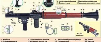
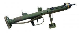
The Dyakonov grenade launcher was a muzzle-loading system. This product was also called a mortar, which, together with a bipod, a bayonet and a quadrant protractor, was equipped with a 7.62 mm rifle. The design of the mortar included the following parts:
- The body, which is represented directly by a rifled barrel. The existing three grooves were intended for the leading protrusions of the grenade.
- Cup.
- Neck. This element was equipped with a special shaped cutout, thanks to which the cup could be attached to the barrel like a bayonet.
The grenade launcher used a threaded connection to attach parts. In an effort to give the rifle stability during operation at various angles, it was equipped with a bipod. When the grenade launcher was installed, the legs of the bipod with their sharp ends were stuck into a hard surface. A clip was attached to the bipod stand and a rifle unit was inserted into it. It was possible to attach the clip using a clamp at different heights. The rifle grenade launcher was aimed using a quadrant goniometer. To install the protractor, a special clamp was used, the left side of which served as a place for the quadrant box, and the right side for the protractor and sight line. Using a quadrant, the elevation angle was verified when aiming vertically, and a protractor - in the horizontal plane. In 1932, a special manual was published describing the design of the Dyakonov grenade launcher. The manual also contained information about the characteristics and combat capabilities of ammunition for the weapon of this system, the rules for their storage and operation.
Notes[ | ]
- ↑ 1 2 3 4 Kashevsky V. A.
Hand-held offensive-defensive grenade RGD-33 // Infantry weapons of the Second World War. - Mn.: Harvest, 2004. - P. 380-381. - Divisional Commissar A. Tarasov, inspector of physical training and sports of the Red Army. New manual on hand-to-hand combat // Red Star: gas. - No. 221 (4071) dated September 24, 1938. - P. 2.
- Novikov V.V.
About training in grenade throwing in the ABT troops // Automotive and Armored Journal: journal. - No. 12, December 1938. - P. 23-28. - ↑ 1 2 3 A. Belyaev.
New manual on hand grenades // Red Star: gas. - No. 297 (4147) dated December 28, 1938. - P. 2. - N. I. Kondratiev. A device for connecting hand grenades into a bundle. Invention Patent No. 67354 (Class 72d, 17).
- Denis Pavlenko.
Soviet grenade RGD-33 (Russian).
zeir.ru.
_ Retrieved June 22, 2020. - Manual on the shooting of the Red Army in 1938 (NSD-38). - M.: Voenizdat, 1939.
- Mikhail Repkin.
“Pocket artillery” of the staff captain // Mastergun: journal. - No. 5 (98), May 2005. - P. 18-19. - Lavrinovich E.V.
Fire rails. — 2nd ed. - Mn.: Belarus, 1974. - P. 27-30. - Training and simulation grenade type RGD-33 designed by Comrade Raffe // Military Bulletin: journal. - No. 10, 1939. - P. 43-48.
- G. V. Mizikovsky. “Thank you, comrade military leader!” M., “Enlightenment”, 1987. p.97
- S. Fedoseev. Soviet infantry throwing shells // “Military-Industrial Courier”, No. 39 (355) dated October 6, 2010
- Weapon of Victory / coll. ed., rep. ed. V. N. Novikov. — 2nd ed. - M.: Mechanical Engineering, 1987. - P. 397.
Thus, during the expedition of the Ministry of Defense of the Russian Federation and the Russian Geographical Society to the island of Shumshu in September 2014, several dozen RGD-33 hand grenades were found at the sites of battles in August 1945.
—
Aleksandrov S.A.
The last battle of the 2nd World War // Technology for youth: journal. - No. 14, 2015. - P. 46-47. — ISSN 0320-331X.- RGD-33 stick grenade / Internet Movie Firearms Database.
Components: body
The design of the RGD-5 grenade is a combination of three main elements:
- housings;
- charge;
- fuse.
Let's consider each of them separately.
The RGD-5 hand grenade has a body that, with the help of a charge placed inside it, is split into the maximum possible number of fragments when it explodes. The shell of a combat unit consists of:
- top part;
- lower half.
The upper part of the body is a combination of three elements: a cap, its liner and a tube. The latter is designed to connect the grenade and the fuse directly. Also, thanks to the tube, the charge, which has a breaking force, is sealed. It is attached to the cap using a cuff. For more careful storage, the grenade tube is equipped with a plastic plug, which also prevents dirt from getting inside. In combat conditions, this plug is replaced by a fuse.
At the bottom of the body there is a tray and its liner.
The outer shell of the RGD-5 grenade also has markings, which are applied with special black paint. The inscription includes the following information:
- short name of the combat unit;
- batch number;
- encrypted year of equipment;
- symbolic designation of the explosive inside the grenade;
- the plant, or rather its number, where the gun was manufactured.
In service[ | ]
- USSR - before the start of the Great Patriotic War, it was the most popular hand grenade in service with the Red Army[13]. The main stocks of RGD-33 grenades were used up in the initial period of the Great Patriotic War[1], but a certain amount remained in service with troops in the Far East, and subsequently they were used in the summer of 1945 during the war with Japan[14].
- Germany - captured hand grenades were used under the name Handgranate 337 (r)
.
Hitting the target
To throw the RGD-5 grenade, you must first remove the safety pin. In this case, the lever is pressed tightly against the body of the combat equipment and is held until the moment of throwing. Next, the spring is activated. She turns the safety lever, releasing the firing pin. That, in turn, under the influence of a spring interacts with the igniter primer. The flame spark from it goes to the moderator, and then, after complete burnout, to the detonator charge. This leads to the grenade exploding.
The final weight of the RGD-5 grenade is 315 g. This small mass allows soldiers to throw a unit at a distance of 50 to 60 meters.
To throw a grenade, you need to go through several stages:
- to begin with, you should take the projectile in your hand so that the safety lever is closely adjacent to the body;
- then you need to unclench the “antennae” of the checks;
- pull it out of the fuse and throw the RGD-5 at the intended target.