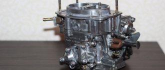
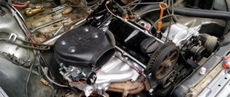
The Solex carburetor (DAAZ) is one of the most popular devices in the list of carburetor metering systems, since with the right approach it is possible to flexibly configure carburetors of this type. For this reason, car enthusiasts install Solex carburetors on different engines, after which they are further adjusted, achieving the required fuel efficiency indicators, quality of mixture formation at power and other operating modes of the internal combustion engine.
We also recommend reading the article on how you can do carburetor tuning yourself. From this article you will learn about various ways to independently modify carburetor metering systems.
After installing Solex on the engine, it is often necessary to configure this device. To solve the problem, you can contact a service center, where a specialist in setting up the carburetor will perform all the necessary operations. You can also adjust the carburetor yourself. In this article we will talk about how to adjust the quality of the mixture on a Solex carburetor, how to adjust the fuel level and adjust the float chamber of the Solex carburetor, adjust the idle speed, etc.
Solex carburetor: setting and adjustment
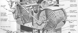
Before starting the setup work, if it is necessary to adjust the carburetor air damper, the fuel level in the chambers, setting the idle speed and other manipulations, it is necessary to separately study the design of the carburetor system, the location of the jets and other basic elements (econostat, economizer, float, first and second chamber, dampers, etc.) You should also pay attention to how the cover is removed and the carburetor is disassembled.
We also recommend reading a general article about the structure and principle of operation of a carburetor. In this article you will learn about the main components of a mechanical dispensing device.
You need to start setting up by setting the fuel level in the float chambers. The recommended method is to set the specified level according to the position that the floats have in relation to the carburetor cover. All manipulations are carried out using a separate template. Note that, as practice shows, this method cannot in any way be considered optimal, since when installing Solex on a car, it should be taken into account that the fuel pump on one specific vehicle may differ from the fuel pump on another car. There may also be other differences in the power supply system. The result is that the pressure on the carburetor needle (carburetor shut-off valve) is also different. Most often, after tuning according to the template, fuel enters the carburetor in large excess. In order to accurately set the gasoline level in the carburetor and adjust the Solex carburetor float successfully, you must follow the steps described below.
- Usually, immediately after installing Solex on different internal combustion engines with different displacements, even without preliminary adjustments, the engine should still start. The engine must be started, after which the power unit should run for about 10 minutes. When running at idle, you can lightly press the gas and increase the speed to avoid the engine shooting into the carburetor or exhaust system.
- Then the power plant can be turned off, after which it is necessary to remove the fuel supply hose. It is recommended to prepare a rag to remove any remaining gasoline that splashes after removing the said hose. The hose is removed so that after removing the carburetor cap, gasoline, which is under pressure in the hose, does not spill into the carburetor chamber. In other words, excess fuel entering the chamber can interfere with the accuracy of the measurements.
- Now you can unscrew the screws securing the carburetor cover, then you need to remove the cable that controls the “choke”. The next step is to carefully lift the carburetor cover. The specified cover should be lifted in a strictly horizontal position so as not to cause damage to the floats themselves.
- Next, you should prepare a ruler or caliper.
With these tools you need to measure the distance that is obtained from the fuel itself in the chamber to the adjacent surface of the carburetor cover. The indicated distance from the surface of the cover to the surface of the fuel should be about 2.5 cm. We add that the distance must be measured in both chambers. This distance may vary, taking into account that the collector is not in a strictly horizontal position. Based on the difference in distances in both cameras, an average value is selected. If the fuel level is insufficient or exceeds the required level, then the tongue of the floats must be very delicately bent for less or more filling. Then the excess gasoline must be removed from the chambers to more accurately determine the level obtained after adjustments at the next measurement. The carburetor should be assembled, after which the engine starts again. - After the engine has been started, it is necessary to illuminate the carburetor chambers with a test lamp or flashlight, observing the small diffusers. During the period from 30 seconds to 1 minute, fuel should not drip from the diffusers. If you notice even a small drop, then this indicates that there is an overflow in the chamber. Please note that you cannot accelerate while observing the diffusers; the engine should only run at idle. The fact is that an unexpected shot or sneezing into the carburetor while applying gas can lead to eye injury.
If no drops of fuel were noticed, then all that remains is to re-measure the fuel level in the chamber using the already known method. If the result is positive, this part of the setup can be considered complete. If the level again differs from the norm, then the level should be adjusted again. Note that setting the level with the engine turned off during manual pumping is not correct, since after starting the internal combustion engine the carburetor will still overflow, especially on engines where the return line has been blocked.
Solex carburetor: idle speed adjustment
The next step after adjusting the fuel level in the carburetor float chamber is to adjust the idle speed. To set up, you must first warm up the engine until it reaches operating temperature. After warming up, the unit should be turned off.
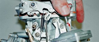
At the very beginning, you need to find the air-fuel mixture quality screw, which is rotated using a flat-head screwdriver. The specified screw is located in the hole, which is made in the lower part of the carburetor.
- The quality screw must be tightened until it stops. Screwing is carried out clockwise, and there is no need to apply force, as the thread can be damaged. After the screw stops, you should turn it back from the stop position by 4-6 turns.
- Now the engine should be started, the choke should be removed. Then you should set the minimum permissible speed by turning the quantity screw. Such minimum speed can be considered an indicator when the engine operates stably and steadily. Also, the vacuum in the vacuum advance fitting should be minimal. A fairly simple way to determine the vacuum is to close the tube that goes into the so-called vacuum advancer with your tongue. If the idle speed is in the range from 600-1200, the carburetor is fine.
- Next, the quality screw must be slowly tightened until the operation of the unit begins to lose stability. As soon as the engine begins to operate unstably, you should unscrew the screw back one or one and a half turns, catching the position when the motor is operating stably again
- We return again to the quantity screw, with which the idle speed should be set to 800-950 rpm. We set the speed screw at XX to about 850-900. If the engine stalls when setting such speeds, then you need to unscrew the quality screw.
- The quality and quantity screws are adjusted until the required idle speed is set, the vacuum in the advance tube will be minimal, and the internal combustion engine itself will be able to operate stably.
Please note that during the setup process you may encounter certain difficulties. For example, the operation of the engine may not change in any way when trying to tighten the quantity screw (normally, the speed should drop, the engine starts to run unevenly, then stalls as the screw is tightened). If this does not happen, then a large amount of fuel enters the idle channel, which cannot be blocked by the quality screw.
This problem arises for a number of reasons. First of all, a large idle jet can be installed. You should also pay attention to how tightly the solenoid valve or plug is screwed in. If the fit is not tight, excess gasoline may be sucked in bypassing the idle jet. Also, one should not exclude possible problems with the jet itself, as well as with its seat. To more accurately understand the reason, you will need to remove the solenoid valve wire with the engine running and idling. In this case, after removal, the unit should quickly stall. If this is the case, then the cause is most likely a large idle jet. The solution will require installing a smaller jet.
If the engine does not stall after removing the wire from the valve, then this problem may arise as a result of gasoline overflowing into the float chamber. It is also possible that when the internal combustion engine is running, fuel bypasses the jet or even the entire idle system. First of all, we again check that the level in the float chamber is set correctly. If everything is normal with the level, then the solenoid valve/plug should be unscrewed, after which you need to inspect the nozzle and its installation location. There should be no defects. If there are any, then the carburetor cap may need to be replaced. If no defects are found, then the jet is put on the valve, the O-ring is lubricated with engine oil, after which it is tightened with a wrench without effort.
Preliminary work
Before starting the main work, it is necessary to prepare the working part.
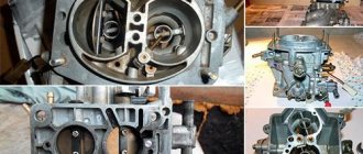
- At the very beginning, the air filter housing is removed. To remove it you need to unscrew the nut that holds the cover from the housing. A ten millimeter wrench will help with this. The cover is held in place by four latches; they will need to be removed. After this, the hose clamp for ventilation is loosened and the hose itself and the filter element are removed. To completely remove the filter housing, all that remains is to unscrew the four nuts (with an 8 mm wrench) that secure it to the carburetor.
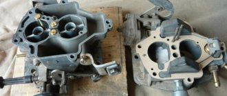
- Next will be the removal of the carburetor cover. To remove it, you need to loosen the clamps on the fuel hoses and then remove these hoses from the carburetor fittings. Remove the wire and unscrew the screws that secure the cover to the body. Then you need to lift the carburetor cover quite a bit. The main thing here is not to touch the chamber walls with the floats.
- The cover must be turned upside down and placed on a flat surface without losing any of the screws that fall out of the cover.
- Check the floats. There must be parallelism between the side surfaces of the floats and between the imprint of the walls of the float chamber. If there is no parallelism, then you need to create it by bringing these same floats together and spreading them apart. As a result: they will be easily located inside the chamber and will not touch its walls.
- Take measurements relative to the cardboard spacer and the protrusion of each float. You need to use a probe, a thin drill, or a wire with a diameter of one millimeter. If the measured distance differs from the required one, it does not matter in which direction: more or less. This indicates that the fuel level in the float chamber is incorrectly set and it is necessary to react to the fuel level again.
Jets and accelerator pump
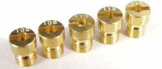
Owners of carburetor cars know that jets change, but they do not always understand why jets are needed and how their size affects the operation of the carburetor. Let's start with the fact that the engine sucks in air through a special hole made in a large diffuser. At the same time, a certain amount of fuel is drawn through the fuel nozzle. The engine displacement directly affects how much air the engine will draw through the diffuser in a certain time, as well as the amount of gasoline sucked in parallel with the air.
It is for this reason that large-volume engines have carburetors with small jets. Installing such a carburetor on an engine with a smaller volume will mean that the “original” jets in this carburetor will produce a mixture that is too lean for normal engine operation. To solve this problem, you should find jets from a carburetor, which was initially designed for a specific internal combustion engine volume or as close as possible to it. You need to select jets starting with the fuel jet, then select the air jet under the fuel jet. The selection is made from a group of jets for the first chamber, the second chamber is adjusted only after the first.
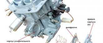
Now let's talk about the accelerator pump. The accelerator pump delivers additional fuel when the throttle valve opens, allowing for more efficient acceleration. The pump is activated using a special cam. On engines with a Solex carburetor installed, the indicated accelerator pump cam must be set to the largest one.
You should also pay attention to the so-called “spout” of the accelerator pump. When the valves are opened, fuel should flow in a clear stream and not drip even with a slight throttle opening. It is also important what position the nose occupies. The stream of gasoline must fall exactly into the area between the diffuser wall and the throttle valve, that is, the fuel is jetted directly into the manifold. The jet must not hit the diffuser or damper. If this happens, then after sharply pressing the accelerator pedal the car will not accelerate immediately, and a failure will occur. Self-refinement of the carburetor involves installing two spouts in the chambers to obtain better performance from the engine, or only one spout in the first chamber of the carburetor for a more economical mode.
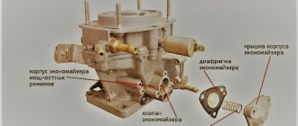
Features of the carburetor float chamber mechanism
The float chamber is located in the front part of the carburetor body. The top is closed with a lid, and gasoline enters the chamber through a fitting. After the fitting there is a filter made in the form of a mesh, the cleanliness of which should be periodically monitored.
The carburetor float most often has a cylindrical shape, made from two brass halves that are soldered together. The float fasteners are made of the same alloy and are secured by soldering. The float is attached to the carburetor cap using a connection.
There are two tongues on the float mount: one is responsible for adjusting the opening of the valve needle, and the second is designed to limit the stroke of the float (so that it does not touch the bottom of the float chamber). The valve is a mini body screwed into the top cap of the carburetor, inside of which there is a needle. A spring damping ball is installed at the end of the needle. This mechanism protects the needle from impacts against the valve body. To prevent the needle from getting stuck in the closed state, a specific bracket is put on it, which is pulled down by the float mounting tab.
- How to adjust a Solex carburetor
From time to time you should check the tightness of the needle valve, as damage to this device can lead to unstable engine operation and increased gasoline consumption. The height of gasoline in the float chamber affects the quality of the fuel mixture that enters the combustion chamber. A low level slows down the fuel supply, and a high level increases its quantity. This is why you need to properly adjust the fuel level in the carburetor float chamber.
Carburetor transition setting
While the engine is idling, the throttle valves are closed. A vacuum (vacuum) is formed under the dampers. Thanks to this vacuum, gasoline is sucked out through a small idle channel and nozzle, and the engine itself runs smoothly at idle. If you open the damper sharply, then the vacuum also weakens. Moreover, this vacuum is not enough for normal operation of the MDS (main dosing system) in the first chamber, and the idle system and accelerator pump are not yet capable of normalizing engine operation. In other words, when you sharply press the gas after idling, there is a delay in the response to pressing the accelerator pedal.
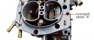
To minimize or completely eliminate this failure, a transition system is used in the carburetor device. This diagram is a hole-slot made above the throttle valve in the first chamber. At the moment you press the gas pedal, the slot-shaped hole appears in a zone of high vacuum, due to which intensive fuel suction occurs parallel to its supply through the idle jet.
Let's go back to the settings. After the carburetor has been installed, many cars experience a failure when starting from a stop, reactions to pressing the gas pedal are slow, and the engine may start shooting at the carburetor or stall. In such a situation, the transition system may be to blame. In order to normalize the operation of the carburetor, it is necessary to correctly select the cross-section of the “spout” of the accelerator pump and the size of the idle jet.
The fact is that it is during operation in the transition mode that fuel comes from both the accelerator pump and the transition system. As a result, the fuel-air mixture may become too rich or, conversely, lean, which does not allow the engine to operate normally and gain speed.
It is important to know that the nozzles in the first chamber do not need to be touched, and the indicated failures should not be attempted to be eliminated by replacing the nozzles of the main dosing system. To solve the problem, use a previously built carburetor to correctly select the idle jet and the accelerator pump spout. The selection must be made after the internal combustion engine has warmed up, the choke must be removed.
In practice it looks like this:
The level in the float chamber was previously set and the idle speed was adjusted. A warm engine idles normally without chugging. A stream of gasoline from the accelerator pump nozzle hits the manifold. Now you can sharply press the gas pedal. What is needed is the sharpness of the press, and not how hard the pedal was pressed (to the floor, half a stroke or ¼). Normally, the motor should immediately respond and spin up, that is, the speed increases without delays or failures. If the response to a sharp press on the accelerator is slow or there is a noticeable pause before the speed increases, then you should go to the settings.
To accurately determine the cause, you need to press the gas pedal again, but this time smoothly and not sharply. If in this case there is an even increase in speed (without pauses, dips or delays), then you should pay attention to the idle jet and the pump spout, since the main dosing system has nothing to do with the failure. If, when you gently press the gas, the engine spins up poorly, the unit itself begins to work jerkily, hums, vibrates strongly, etc., then the problem lies in the selection of jets for the first chamber. In other words, excessive enrichment or leanness of the mixture occurs after the carburetor switches to power mode after pressing the accelerator. An indirect sign of a too “rich” mixture during operation in transition mode is that the engine emits black smoke and the smell of gasoline comes from the exhaust system. The specified smoke and smell appear after sharp throttling.
To remove the dip, you must carefully select the idle jets to match the pump spout or vice versa. This is done until the delay disappears when you sharply press the accelerator pedal. In parallel with this, it may be necessary to re-adjust the idle speed, since replacing the XX jet will make changes to the operation of the idle system. Let us add that if the mixture remains lean and there is a dip, and the idle jet is too large and it is not possible to adjust the idle speed, then you can install a paired pump spout, after which both tubes are bent into the first float chamber.
Basic faults of Solex 21083
There are malfunctions that are most typical for Solex carburetors:
- clogging of the fuel jet of the GDS;
- the entry of debris into the idle system; the XX jet in the solenoid valve is especially often clogged;
- deformation of the lower surface of the main body due to overheating;
- failure of the accelerator pump diaphragm;
- solenoid valve defect;
- loose fit of diffusers in the housing.
If the body is deformed, air is sucked between the carburetor and the intake manifold, and the engine begins to operate intermittently, as the air-fuel mixture becomes leaner. The idle speed is difficult to adjust, and to correct the defect it is necessary to grind the surface on an emery wheel. If the surface warping is significant, grinding will no longer help; the housing must be replaced.
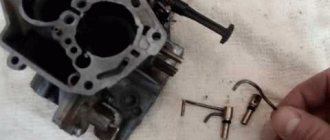
Over time, the accelerator pump diaphragm can crack, lose elasticity, and ruptures appear in it.
Checking the condition of the diaphragm is quite simple; it does not require removing the carburetor. To get to the diaphragm, you need to unscrew the 4 screws of the accelerator pump cover and remove the part. The condition of the diaphragm is checked by external inspection.
When do you need to adjust the fuel level in the carburetor? The carburetor must be adjusted after:
- Work performed that involved removing the carburetor floats.
- And also if the fuel supply to the carburetor is interrupted.
Adjusting the second chamber of the Solex carburetor
Let's start with the fact that when adjusting the carburetor, the second chamber is usually not touched, since often standard jets will be sufficient. The carburetor also has an econostat that can correct possible nuances. The econostat is a tube located in the second chamber at a slight angle.
The purpose of the econostat is that when the throttle is fully opened, the vacuum in the carburetor allows fuel to be sucked through the econostat. The econostat is activated when the engine is running at high speeds and allows the fuel-air mixture to be enriched. To refine the second chamber, which allows for “pick-up,” jets are installed to enrich the mixture. The selection of jets in this case is no different from the selection for the first chamber.
Adjusting the fuel level in the Solex carburetor 21083, 2108, 21081
When the carburetor cover is removed, everything should look like this. The approximate fuel depth level should be approximately twenty-nine millimeters plus or minus one millimeter. The level must be measured immediately after the carburetor cap is removed. It is necessary to do this immediately only so that the gasoline does not evaporate. But you need to understand that the numbers given in the article are not an exact number, they are just an average value.
Sometimes those who repair cars use conditional values in order to correctly set the fuel level. Such repairmen spontaneously control the tongue located on the float lever. They also sometimes pump up fuel to achieve the optimal level in the float chamber.
However, they are not guided by anything to do these actions. This approach has its place, but in order to achieve more accurate and accurate results, it is necessary to perform the usual standard fuel adjustment. At a minimum, standard adjustment is recommended by factories, and no special skills are required to carry it out. This adjustment is carried out in two simple steps on the carburetor cover turned upside down and positioned horizontally.
Let's sum it up
The steps described above for setting up and adjusting a Solex carburetor are basic. In other words, if you wish, you can adjust the carburetor yourself, based on this information. Note that the accuracy of the settings can be further checked on a gas analyzer, after which you can make the necessary adjustments yourself instead of constantly contacting specialists. Finally, we add that a dosing device of this type lends itself to various types of tuning, all kinds of modifications and improvements. For this reason, when choosing a carburetor for a VAZ, it is not for nothing that many car enthusiasts prefer Solex.