The internal combustion engine (hereinafter referred to as ICE) has been installed in cars for more than 100 years. During this time, the unit has gone through a long development path. Currently, the design of internal combustion engines has been improved so much that it makes it possible to combine high efficiency with reliability and durability.
But nothing lasts forever, and over time the motor becomes unusable. The operating principle of the engine has remained virtually unchanged; accordingly, the characteristic malfunctions remain the same as before.
In order for the internal combustion engine to work for its intended period without serious breakdowns, it is important to promptly detect and eliminate any malfunctions that have arisen. It is not always possible to conduct a full diagnostic of the engine condition using technical centers equipped with professional equipment. The driver must have the ability to assess the condition of the engine based on indirect signs that appear when malfunctions occur.
Main signs of engine malfunction
The service life of modern engines varies widely. Highly accelerated engines last no more than 150 thousand km, while diesel engines on multi-ton tractors can travel 1 million km or more before major repairs. This mileage greatly depends on operating conditions. The condition of the engine is influenced by the following factors:
- use of low-quality fuels and lubricants;
- operation in difficult conditions;
- aggressive driving style;
- engine temperature exceeds permissible limits;
- non-compliance with service intervals.
The motor does not immediately fail. It starts up and works, but over time it louder and louder declares that it will soon require diagnostics and replacement of worn-out parts, or even a major overhaul of the engine or replacement of its entire assembly. The sooner the driver detects signs of malfunction, the easier and cheaper it will be to make repairs. Untimely intervention leads to new breakdowns and the engine becomes unusable.
You should be wary of characteristic signs that appear only in faulty motors.
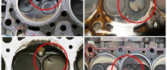
Basic malfunctions of internal combustion engines. Listening areas.
Determination of increased oil consumption due to waste: the condition of the spark plug is not tight (seals, cracks are visible to the eye), there is a loss of power and unstable engine operation.
Determination of power loss: by the condition of the cylinders, valves, the presence of catalysts, hydraulic shock, valve timing, fuel air, overheating of the connecting rod / crankshaft.
Extraneous noise, knocking in the engine.
Determination of instability of idling: by burnout of gaskets, valves, cylinder rings.
Oil starvation is determined by debris in the pan, jammed shafts, and stuck valves.
Overheating is fraught with vibrations, oil leaks, and popping noises in the exhaust system.
Main malfunctions of internal combustion engines, causes
If a cold engine does not start or starts but with difficulty, these are the main malfunctions of the injection systems. Possible reasons for this:
the starting injector or its circuit (for vehicles with a starting injector) is faulty;
fuel pressure is insufficient or missing;
the signal from the crankshaft speed sensor is weak or absent;
increased resistance from the exhaust system;
air is brought into the intake manifold;
The throttle potentiometer is faulty.
If a hot engine does not start or starts but with difficulty, then the possible reasons are as follows:
Fuel pressure drops quickly after turning off the engine;
the coolant in the temperature sensor circuit is faulty;
the absolute pressure sensor circuit is faulty;
· malfunction of the flow meter in the circuit.
If the internal combustion engine starts in idling mode, but stalls or its operation is unstable, then the possible reasons are as follows:
1) the idle system itself is faulty;
2) air is sucked into the intake manifold;
3) the fuel pressure does not correspond to the specified one;
4) the air flow meter circuit is faulty.
If the crankshaft speed at idle is too high, then the possible reasons are as follows:
1) the operation of the idle system itself is incorrect;
2) there is a malfunction in the throttle position sensor circuit;
3) air is sucked into the intake manifold, etc.
If the engine does not develop full power, then the possible reasons are:
1) in the flow meter circuit the air or absolute pressure sensor is faulty;
2) the performance or pressure of the fuel pump is insufficient;
3) nozzles are dirty;
4) the exhaust system resistance is increased.
If fuel consumption and carbon monoxide levels are increased, the possible causes are:
1) there is a malfunction in the oxygen sensor circuit;
2) fuel pressure is increased;
3) there is a malfunction in the air flow meter or absolute pressure sensor circuit;
4) increased exhaust system resistance;
5) there is a rupture in the fuel pressure regulator diaphragm;
6) the coolant in the temperature sensor circuit is faulty.
If the car jerks, there are misfires under load, then the possible reasons are as follows:
1) there is a malfunction in the air flow meter or absolute pressure sensor circuit;
2) there is a malfunction in the throttle sensor circuit;
3) nozzles are dirty;
4) the pressure or performance of the fuel pump is insufficient.
If the oil pressure light comes on before the engine warms up, you need to check the oil filter first. It happens that the filter itself is of poor quality (“left”). Then its valve simply may not work. It is recommended to use the oil filter recommended for the vehicle and preferably a high-quality one (expensive - not always high-quality!). And of course, it’s worth checking the pressure sensor itself for “glitches” (maybe it’s “lying” with the reading), whether the sensitivity has decreased and whether it’s time for a replacement.
If the antifreeze level is below Min, then most likely something is leaking in the engine. When antifreeze gets into the oil, a “mayonnaise”-colored coating forms, and if it looks like boiled condensed milk, the matter is different, perhaps even winter condensation.
It is necessary to check the absence of antifreeze in the oil, most importantly, in the cylinders, as well as the system for the presence of microcracks. If the gasket under the head of the block is new, the plane of the head is normal, then it’s not so scary. You need to buy a bottle of “stop leaking” and fill the problem areas with it - it should help for a while. And then we need to look at the circumstances. It is important that the dipstick is only in oil! If there are traces of mixing with antifreeze on it, this is already a disaster.
If the engine system malfunction icon is on, then in any case it would not be a bad idea to make a diagnosis (for starters). Often, if you remove the “-” terminal from the battery, the fault signal may be reset. As a rule, it most often happens (but not a fact), the signal may indicate that there are problems with injectors, spark plugs, fuel, or damage to the corrugation of the exhaust gas system (up to the 2nd lambda probe). You can first try to reset the signal by removing the “-” terminal. Incorrect operation of the control solenoids-regulators is possible. If the problem recurs, diagnostics are generally irreplaceable.
1.13. ENGINE CONTAMINATION .
General contamination of the car, its components and parts includes external deposits, lubricant residues, carbon deposits, corrosion products, scale and remnants of old paintwork.
These contaminants are different in nature, and therefore the possibilities for removing them from surfaces are different. They have high adhesion (stickiness) and are firmly held on the surface of the parts.
External deposits can be divided into dust-mud and oil-mud.
The atmospheric air always contains a certain amount of dust. Near moving vehicles, the dust concentration increases to 0.05-0.50 g/m3 with a dispersion of 5-30 microns. As the concentration of dust particles increases, their coagulation and deposition on metal surfaces increases. In humid air, particle coagulation accelerates, since the adsorbed moisture film increases the adhesion forces between particles. The retention strength of particles on a surface depends on the cleanliness of the surface, their size and air humidity. Thus, dust particles with a diameter of 1-2 microns, deposited on the surface, have such strong adhesion that they cannot be blown away by a stream of compressed air flowing at a speed of 200 m/s. After the surface of the car dries, washed with a high-pressure water jet, a residue of tiny dust particles remains on it. They can be removed only after mechanically wiping the surface (with a brush or rag).
Oily mud deposits occur when road dirt and dust get on the surfaces of parts contaminated with oil. The opposite phenomenon is possible - oil getting on surfaces contaminated with road dirt. In this case, the dirt is saturated with oil. On average, the adhesion value of external deposits to the surface is 0.05–0.20 kgf/cm2.
Lubricant residues are the most common contamination in engines. During vehicle operation, lubricants undergo significant changes caused by “aging” processes - oxidation and polymerization. Removing oil residues from the surface of parts that have worked for a long time in an oil environment is associated with certain difficulties.
Carbon deposits that appear on engine parts are divided into carbon deposits, varnish-like deposits and sediments. Carbon deposits are solid carbonaceous substances deposited on engine parts (combustion chamber walls, valves, spark plugs, piston crown, etc.). Varnish-like film deposits that form in the area of the piston rings, as well as on the skirt and inner walls of the pistons. Sediments are ointment-like clots deposited on crankcase walls, crankshaft cheeks, camshaft gears, oil pumps, filters and oil lines.
The chemical composition of carbon deposits is studied by group analysis, which consists in isolating a group of substances characterized by solubility in selected solvents. The analysis identifies the following groups of substances: oils and neutral resins, hydroxy acids, asphaltenes, carbenes and carboids, as well as a non-combustible residue - ash.
Neutral resins are substances that are part of the resinous part of oils and their decomposition products. Neutral resins are compounds with a liquid or semi-liquid consistency, completely soluble in petroleum ether and petroleum fractions.
Hydroxy acids are organic acids containing hydroxyl and carboxyl groups. Hydroxy acids are capable of dissociating, forming salts (saponification reactions), and oxidizing.
Asphaltenes, the compaction products of neutral resins, are dark brown or black substances that are hard, brittle, infusible and decompose at temperatures above 300°C to form coke and gases. Asphaltenes are insoluble in petroleum ether, but readily soluble in benzene, chloroform and carbon disulfide; They are not saponified, but are emulsifiers, promoting the formation of reverse emulsions.
Carbenes and carboids are benzene-insoluble products of compaction and polymerization of hydrocarbons that arise during the thermal decomposition of oils and fuels. Carbenes are soluble in carbon disulfide and pyridine; Carboids are insoluble in any solvent.
The main reason for the formation of carbon deposits in engines should be considered thermal oxidation of hydrocarbons. With an increase in the depth of oxidation of oils and fuels, a quantitative increase in hydroxy acids, asphaltenes, carbenes and carboids occurs in the products of their oxidation.
The formation of soot mainly comes down to the following. In high temperature zones, fuels and oils burn, forming solid, non-sticky carbon particles. In the zone of lower temperatures, the oil undergoes less profound changes - oxidation and compaction with the formation of sticky high-molecular compounds. These compounds are deposited on parts in the form of a thin varnish-like film, which has the ability to retain carbon particles of burnt fuel and oil on its surface. As a result of the gradual sintering of these particles, a layer of carbon deposits is formed - soot.
Depending on the design of the engines, their operating conditions, and the quality of the fuel and oil used, carbon deposits may have a different chemical composition. The basis of soot in automotive engines is carbenes and carboids - 30-70%, oils and resins - 8-30%, the rest - hydroxy acids, asphaltenes and ash. Thus, carbon deposits contain a large number of insoluble or poorly soluble components, which makes them difficult to remove.
Thin-layer oxidation of the oil plays an important role in the formation of a varnish-like film. Another important physicochemical process in the formation of varnish films is the coagulation of highly dispersed carbon particles contained in the oil. Thus, oil containing carbon particles (1 micron), falling on heated metal surfaces, almost instantly releases these particles, and at high temperatures their rapid coagulation occurs. The resulting coagulants, deposited on the surface of the parts, serve as the main source material for the formation of varnish films. In relation to automotive engines, varnish films do not play a major role as contamination, since they are deposited only on a small group of parts (piston skirt, part of the connecting rod). In addition, their strength is low and they are removed similarly to sediments from the engine crankcase.
Precipitates consist of products of combustion and physical and chemical changes in fuel and oil, mechanical impurities sucked in with air, wear products of parts and water. Those substances that do not dissolve in oil and have a higher density than them pass into sediments. 40-80% of sediment consists of oils and resins; carbenes, carboids and ash make up 10-30%.
50-70% of the surface of engine parts is contaminated with sediment. These are the most common engine contaminations. The formation of precipitation occurs in two zones: high-temperature (on the parts of the cylinder-piston group) and low-temperature (in the crankcase). The greatest influence on the aging of oil in the lubrication system of a diesel engine is exerted by the operating conditions of the oil in the cylinder liner area. Here the oil, being in a thin film of 3-25 microns, is exposed to combustion products heated to 1200-1500 °C. At the same time, the surface of the oil film on the cylinder liner is renewed with each piston stroke, which provides a contact surface of the film with the working gases, amounting to thousands of square meters per hour for some engines. Instant physical and chemical processes occurring in the oil film have a decisive influence on the overall course of oil aging processes in the entire engine system.
The most intensive change in oil composition occurs during the first period of its operation in the engine. The content of oxidation products in diesel engine oil increases in the first 150-200 hours of operation. Subsequently, the resulting oxidation products, mostly insoluble in oil, form durable asphalt-resin deposits (ASD) on filters, crankcase walls and other parts.
Corrosion products are formed as a result of chemical or electrochemical resolution of metals and alloys. A reddish-brown film forms on the surface of steel and cast iron parts—iron oxide hydrate (rust). Iron oxide hydrate is soluble in acids and only slightly in alkalis and water. Aluminum parts are also subject to corrosion, the products of which have the appearance of a grayish-white coating and are oxides or hydrates of aluminum oxides.
Scale forms in engine water cooling systems during their operation. Deposited on the walls of the engine cooling jacket and radiator, scale complicates heat exchange processes and disrupts the normal operation of the engine. The formation of scale is caused by the dissolved content of calcium and magnesium salts in water, i.e., water hardness. There are temporary (carbonate) and permanent (non-carbonate) hardness. Temporary hardness is caused by the dissolution of calcium bicarbonates Ca<(HC03) and magnesium Mg(HG03)2, calcium sulfate CaS04, magnesium silicate MgSi03, etc. in water.
When water is heated to 70-80 °C or boiled, salts fall out of it - products of thermal decomposition of bicarbonates - CaCO3 and MgC03, as well as silicates and sulfates of magnesium and calcium, which, deposited on the walls, form scale. Constant hardness is due to salts that remain soluble in water at elevated temperatures. There are scales: carbonate (CaC03 and MgC03), sulfate (CaS04), silicate (MgSi03 and CaSi03) and mixed, containing all the above salts.
In addition to scale, silt deposits form in engine cooling systems due to the ingress of mechanical impurities (sand, clay), organic substances (microorganisms, plants) into the system and the formation of corrosion products.
Loss of acceleration dynamics
Over time, the internal combustion engine loses power, which means the car accelerates worse and consumes more fuel. If the decrease in dynamics is the result of natural wear and tear of the engine, then this is normal. Intervention is necessary when power loss reaches 20% or more. It's hard not to feel it.
In addition to engine wear, acceleration dynamics are affected by a host of other faults:
- failure, incorrect operation of power and ignition systems;
- use of substandard fuel;
- transmission malfunctions, for example when the clutch slips.
- high backpressure of exhaust gases in the exhaust tract caused by a clogged catalyst.
There are many other reasons for loss of dynamics, but in any case this is a reason for intervention. You can't do without diagnostics.
Excessive oil consumption
The consumption of lubricants in the internal combustion engine of different cars can vary significantly. In some models, consumption of 1 liter of oil per 1000 km is considered normal. Others, when in good condition, do not require topping up from replacement to replacement. There are several reasons for increased oil consumption:
- wear of the cylinder-piston group;
- failure of valve stem seals;
- coking of the crankcase ventilation channel, as well as other reasons.
When oil enters the combustion chamber, the exhaust acquires a bluish, gray color. In all cases, it is necessary to quickly identify and eliminate the cause of excessive consumption of lubricants.
Possible engine malfunctions and their causes
Poor performance of a warm engine
Fault: increased crankshaft speed of a warm engine in idle mode
Possible reason:
1. Air leaks through leaks in the intake system or crankcase ventilation; 2. Failure of the idle speed controller; 3. The coolant temperature sensor is faulty; 4.Increased gap between the phase sensor and the marker; 5. The injectors are leaky or their nozzles are dirty; 6. Malfunctions of the CMPSUD.
Fault: Engine does not develop full power
Possible reason:
1. Incomplete opening of the throttle valves; 2. Clogged fine fuel filter; 3. Air filter dirty; 4. Engine adjustment in idle mode is disrupted; 5. Air leak; 6. The neutralizer has failed; 7. Increased carbon coating of intake valves; 8. Timing phase violation; 9. Wear of camshaft cams; 10.Excessive carbon formation in combustion chambers; 11. The gap between the spark plug electrodes is not normal; 12.Reduced engine compression; 13.Insufficient spark power; 14. Malfunction of the CMPSUD; 15. The electric fuel pump is faulty.
Fault: insufficient fuel supply
Possible reason:
1.Low fuel pressure; 2. Clogged injectors; 3. Faulty injector windings.
Fault: engine overheats
Possible reason:
1. Insufficient amount of coolant in the system; 2. The thermostat is faulty; 3. Burnout of the cylinder head gasket; 4. Insufficient tension of the auxiliary drive belt; 5. Ignition too late; 6.Impaired coolant circulation; 7. Malfunction of the water pump - rotation of the hub or impeller, wear of the impeller; 8. Contamination of the outer or inner surface of the radiator; 9. Insufficient fan rotation due to slippage of the fan belt or malfunction of the viscous coupling.
Malfunction: increased CO and CH emissions at idle
Possible reason:
1. The oxygen content sensor in the exhaust gases has failed 2. The control unit has failed 3. Leakage in the engine intake tract (air leakage, bypassing the mass air flow sensor) 4. Malfunction of the air or coolant temperature sensors 5. The accelerator drive adjustment is broken or jammed in the drive, due to which the throttle valve does not close completely 6. Malfunction or loss of tightness in the injectors 7. The gaps between the rocker arms and valve stems are broken 8. Interruptions in the operation of the ignition system (faulty switch, ignition coils, spark plugs, breakdown of spark plug tips , incorrect installation of high-voltage wires in the sockets or their breakdown)
Fault: low oil pressure or lack of pressure in the lubrication system
Possible reason:
1. The oil pump pressure reducing valve is jammed in the open position, the plunger spring is broken or weakened; 2. Oil filter clogged; 3. Clogged oil receiver screen of the oil pump; 4. Sticking of the oil filter anti-drainage valve after the car has been parked for a long time; 5. Breakage or weakening of the thermal valve safety valve spring; 6. The oil pressure sensor or indicator is faulty, there is high resistance in the sensor and indicator circuit due to oxidation of the contacts; 7. Engine overheating; 8. Increased clearances in the oil pump, wear of pump gears; 9. Increased clearances in the crank and gas distribution mechanisms in units where oil is supplied under pressure; 10. Reduced oil level in the oil sump; 11.Continuous opening of the oil filter bypass valve; 12.The oil pump drive is faulty; 13. Poor quality engine oil or one that does not correspond to the season of operation has been filled in; 14. Malfunction of the signaling device sensor or short circuit of the wire from the sensor to the signaling device to ground.
Fault: knocking in the engine
Possible reason:
1. Wear of the connecting rod and main bearings of the crankshaft; 2. Wear of the connecting rod and piston group; 3. Wear of the CPG; 4. The hydraulic valve tappet is faulty; 5. The hydraulic chain tensioner is faulty; 6. Increased chain elongation - uniform noise in the front part of the engine, increasing at medium speeds and variable loads; 7. Seizure of the valve stem in the guide sleeve; 8.Drawdown under load of the valve spring; 9. The crankshaft damper pulley is loose. 10. The generator bearing is faulty; 11.Knock of the water pump bearing; 12. Knock of the bearing of the guide roller of the accessory drive belt.
Low oil pressure
All cars have a control indicator on the instrument panel that indicates that the lubricant pressure is below normal. When the warning light goes off, you must immediately turn off the engine and eliminate the cause.
Insufficient pressure can be caused by either a simple lack of oil, a clogged filter, or serious breakdowns, including failure of the oil pump, clogged oil channels, and dilution of the oil by antifreeze through a broken head gasket. These are the most common reasons for a drop in oil pressure.
Fault codes for the engine control system 40900A with the Mikas-11 ECU of the UAZ 316300
Accepted abbreviations:
- KZ - short circuit;
- RAM - random access memory;
- ROM - read-only memory;
- EEPROM - non-volatile memory;
- VUS - high signal level;
- LUS - low signal level;
- FA - fuel-air mixture
| Engine fault code 40900A | Name of faults |
| 0000 | The tester does not identify the error |
| 0101 | The signal from the mass air flow sensor is outside the permissible range |
| 0102 | NUS of mass air flow sensor circuit |
| 0103 | VUS of the mass air flow sensor circuit |
| 0116 | Coolant temperature sensor signal out of acceptable range |
| 0117 | NUS coolant temperature sensor circuit |
| 0118 | VUS coolant temperature sensor circuit |
| 0121 | Throttle position sensor signal out of range |
| 0122 | NUS of throttle position sensor circuit |
| 0123 | VUS of throttle position sensor circuit |
| 0130* | Oxygen sensor circuit is faulty |
| 0131* | NUS oxygen sensor |
| 0132* | Oxygen sensor VUS |
| 0133* | Slow response to rich or lean oxygen sensor |
| 0134* | Oxygen sensor circuit open |
| 0135* | Oxygen sensor heater malfunction |
| 0171* | Fuel system too lean |
| 0172* | Fuel system too rich |
| 0200* | Injector control circuit is faulty |
| 0201 | Open injector control circuit 1 |
| 0202 | Open injector control circuit 2 |
| 0203 | Injector 3 control circuit open |
| 0204 | Open injector control circuit 4 |
| 0217 | Engine cooling system overheating |
| 0219 | Exceeding the permissible crankshaft speed |
| 0230 | Fuel pump relay control circuit malfunction |
| 0261 | Short circuit to ground injector control circuit 1 |
| 0262 | Short circuit to the on-board network or open circuit of injector 1 |
| 0263 | Injector driver 1 is faulty |
| 0264 | Short circuit to ground for injector 2 control circuit |
| 0265 | Short circuit to the on-board network or open circuit of injector 2 |
| 0266 | Injector driver 2 is faulty |
| 0267 | Short circuit to ground for injector 3 control circuit |
| 0268 | Short circuit to the on-board network or open circuit of injector 3 |
| 0269 | Injector driver 3 is faulty |
| 0270 | Short circuit to ground of injector control circuit 4 |
| 0271 | Short circuit to the on-board network or open circuit of injector 4 |
| 0272 | Injector driver 4 is faulty |
| 0297 | Exceeding the permissible vehicle speed |
| 0300* | Random/multiple misfires |
| 0301* | Misfire in cylinder 1 |
| 0302* | Misfire in cylinder 2 |
| 0303* | Misfire in cylinder 3 |
| 0304* | Misfire in cylinder 4 |
| 0325 | Open circuit of the knock sensor |
| 0327 | NUS knock sensor circuit |
| 0328 | Knock sensor circuit VUS |
| 0335 | Crankshaft position sensor circuit malfunction |
| 0336 | Crankshaft position sensor signal is out of range |
| 0337 | Short circuit to ground of the crankshaft position sensor circuit |
| 0338 | Open crankshaft position sensor circuit |
| 0340 | Camshaft Position Sensor Circuit Malfunction |
| 0342 | NUS camshaft position sensor circuit |
| 0343 | VUS camshaft position sensor circuit |
| 0351* | Open circuit of ignition coil 1 |
| 0352* | Open circuit of ignition coil 2 |
| 0422* | Neutralizer efficiency is below acceptable |
| 0441 | Incorrect air flow through the canister purge valve |
| 0443 | Malfunction of the canister purge valve control circuit |
| 0444 | Short circuit to the on-board network or open circuit of the canister purge control circuit |
| 0445 | Short circuit to ground of the canister purge valve control circuit |
| 0480 | No. 1 Fan Relay Control Circuit Malfunction |
| 0481 | No. 2 Fan Relay Control Circuit Malfunction |
| 0500 | No signal from vehicle speed sensor |
| 0501 | Speed sensor circuit malfunction |
| 0503 | Intermittent speed sensor signal |
| 0505 | Idle air control circuit malfunction |
| 0506 | Low idle speed (idle speed control locked) |
| 0507 | High idle speed (idle speed control locked) |
| 0508 | Short circuit of the idle speed control stepper control circuit to ground |
| 0509 | Short circuit of the idle speed control stepper control circuit to the on-board network |
| 0511 | Open circuit for idle speed control stepper control |
| 0560 | The on-board voltage is below the operating threshold |
| 0562 | Reduced voltage on-board network |
| 0563 | Increased voltage on-board network |
| 0601 | Controller ROM malfunction |
| 0602 | Controller RAM malfunction |
| 0603 | Faulty internal RAM of the controller |
| 0604 | Faulty external RAM of the controller |
| 0615 | Open starter relay control circuit |
| 0616 | Short circuit to ground of starter relay control circuit |
| 0617 | Short circuit on the starter relay control circuit board |
| 0627 | Open circuit in the fuel pump relay control circuit |
| 0628 | Short circuit to ground of the fuel pump relay control circuit |
| 0629 | Short circuit on the on-board network of the fuel pump relay control circuit |
| 0630 | VIN code storage fault or vehicle VIN code is not recorded in the controller |
| 0645 | Open air conditioner clutch relay control circuit |
| 0646 | Short circuit to ground of the air conditioning clutch relay circuit |
| 0647 | Short circuit on the circuit board of the air conditioner clutch relay circuit |
| 0650 | Check engine lamp circuit malfunction |
| 0654 | Instrument panel tachometer circuit malfunction |
| 0685 | Main relay control circuit open |
| 0687 | Short circuit on the main relay control circuit |
| 0688 | Open circuit in the main relay output |
| 0690 | Short circuit on the main relay power circuit board |
| 1102* | Oxygen Sensor Heater Resistance Low |
| 1115* | Oxygen sensor heater control circuit malfunction |
| 1123* | The mixture is “rich” - additive correction of fuel assemblies by air exceeds the set threshold |
| 1124* | The mixture is “lean” - the additive correction of the fuel assembly by air exceeds the set threshold |
| 1127* | The mixture is “rich” - the multiplicative correction of the fuel assembly composition exceeds the established threshold |
| 1128* | The mixture is “lean” - the multiplicative correction of the fuel assembly composition exceeds the established threshold |
| 1135* | Oxygen sensor heater malfunction |
| 1136* | The mixture is “rich” - the additive correction of the fuel assembly exceeds the set threshold |
| 1137* | The mixture is “lean”—the additive correction of the fuel assembly exceeds the set threshold |
| 1140 | Incorrect air flow sensor signal |
| 1386 | Internal detonation channel test error |
| 1410 | Short circuit to the on-board network or open circuit for controlling the canister purge valve |
| 1425 | Short circuit to ground of the canister purge valve control circuit |
| 1426 | Open canister purge valve control circuit |
| 1500 | Open circuit in the fuel pump relay control circuit |
| 1501 | Short circuit to ground of the fuel pump relay control circuit |
| 1502 | Short circuit to the on-board network or open circuit of the fuel pump relay |
| 1509 | Idle air control control circuit overload |
| 1513 | Short circuit to ground of idle air control control circuit |
| 1514 | Short circuit to the on-board network or open circuit of the idle air regulator control circuit |
| 1541 | Open circuit in the fuel pump relay control circuit |
| 1570 | No response from APS (immobilizer) or open circuit |
| 1571 | Unregistered key used |
| 1572 | Broken immobilizer antenna |
| 1573 | Internal malfunction of the APS unit (immobilizer) |
| 1600 | No connection with APS (immobilizer) |
| 1601 | No connection with APS (immobilizer) |
| 1602 | Loss of on-board voltage |
| 1603 | Controller EEPROM malfunction |
| 1606 | Incorrect rough road sensor signal |
| 1612 | Controller reset error |
| 1616 | NUS rough road sensor |
| 1617 | VUS sensor |
| 1620 | Controller ROM malfunction |
| 1621 | Controller RAM malfunction |
| 1622 | Controller EEPROM malfunction |
| 1640 | Failure to access controller EEPROM |
| 1689 | Incorrect error codes in the controller memory |
| 1750 | Short circuit to the on-board network of circuit No. 1 for controlling the idle speed regulator |
| 1751 | Open circuit No. 1 for controlling the idle speed regulator |
| 1752 | Short circuit to ground of circuit No. 1 of the idle speed regulator torque control |
| 1753 | Short circuit to the on-board network of circuit No. 2 for controlling the idle speed regulator |
| 1754 | Open circuit No. 2 for controlling the idle speed regulator |
| 1755 | Short circuit to ground of circuit No. 2 of the idle speed regulator torque control |
| 2301* | Short circuit on the circuit board of the ignition coil 1 |
| 2303* | Short circuit on the circuit board of ignition coil 2 |
| 3999 | Synchronization violation according to the crankshaft position sensor |
Note. Due to differences in the composition of engine control systems, individual fault codes may not be identified
* Failure may lead to failure of the neutralizer
Decoding fault codes for engine 40900A with ECU Mikas-11 of UAZ 316300
Codes “0102, 0103” - malfunction of the mass air flow sensor circuits. Possible causes of the malfunction: the sensor is installed in the opposite direction to the air flow, the sensor type does not match the nameplate type of the engine control unit, the sensor is not connected to the ECM wiring harness, an open circuit of the sensor signal circuits or its power supply circuits, incorrect (reverse) polarity of connecting the signal wires from the sensor to the unit, short circuit of the signal wire to ground or on-board network, malfunction of the unit's measuring channel (inputs: 7 - plus and 6 - minus), sensor malfunction or contamination of its sensitive element
Codes “0117, 0118” - malfunction of the coolant temperature sensor circuits. Possible causes of the malfunction: the sensor is not connected to the ECM wiring harness, an open or shorted to ground signal circuit, a malfunction of the unit's measuring channel, a sensor malfunction (open or internal short circuit).
Codes “0122, 0123” - malfunction of the throttle position sensor circuits. Possible causes of the malfunction: incorrect installation of the sensor on the throttle (zero offset), the sensor is not connected to the ECM wiring harness, a break or short to ground in the signal circuit, the signal and power wires from the sensor to the unit are reversed, a break or short to ground in the sensor power wire (+ 5B), malfunction of the unit’s measuring channel, malfunction of the sensor itself.
Codes "0130-0133" - malfunction of the oxygen sensor circuits. Possible causes of the malfunction: the sensor is not connected to the ECM wiring harness, open or shorted to ground signal circuits, signal circuits and sensor heater circuits are mixed up, open or shorted sensor heater circuits (H+/H-), malfunction of the unit's measuring channel, sensor malfunction: contamination or melting.
Codes “0171, 0172, 1123-1137” - rich/lean mixture when controlling fuel supply using an oxygen sensor. Possible causes of malfunction: malfunction of the oxygen sensor, malfunction of the oxygen sensor heater circuit (H+ and H-), high or low fuel pressure.
Codes “0200-0204, 0261-0272” - malfunction of the injector control circuits of cylinders 1/2/3/4. Possible causes of the malfunction: the injector is not connected to the ECM wiring harness, a break in the injector power supply circuit from the main relay, a break in the ground wire from the unit, an open or short circuit to ground/on board of the injector control circuit, a malfunction of the injector control power channel, an injector malfunction: short circuit of the electromagnet winding injectors (active resistance below 10
Codes “0300-0304, 0352, 0352, 2301, 2303” - malfunction of the control circuits for the ignition coils of the 1/4th and 2/3rd cylinders. Possible causes of the malfunction: the ignition coil is not connected to the wiring harness, an open circuit in the ignition coil power supply from terminal “15” of the on-board network, a break in the ground wires from the unit, an open or short circuit to ground/onboard of the coil control circuit, a malfunction of the power channel for controlling the ignition coil, a malfunction of the coil : short circuit of the primary winding (active resistance below 0.35 Ohm) or short-circuited turns in the secondary winding (active resistance below 12 kOhm), malfunction of high-voltage circuits or spark plugs.
Code "0325-0328" - malfunction of the knock sensor circuits. Possible causes of the malfunction: poor installation (mounting) of the sensor on the engine, the sensor is not connected to the ECM wiring harness, an open circuit or short to ground, a broken or broken shielding braid of the sensor wires, a malfunction of the unit’s measuring channel, a malfunction of the sensor itself.
Code "0335-0338, 3999" - malfunction of the crankshaft position sensor circuit. Possible causes of the malfunction: violation or breakage of the shielding braid of the sensor wires, malfunction of the secondary circuit of the ignition coil (short-circuited turns), malfunction of high-voltage wires or tips (increased noise), the sensor is not connected to the wiring harness, presence of water in the sensor connector, short to ground or the screen of one of the signal wires 48/49 of the sensor, the polarity of the signal wires of the sensor is reversed, increased or decreased mounting gap between the end of the sensor and the tooth of the synchro disk (normal gap is 0.5-1.2 mm), increased radial runout of the synchronization disk, damage to the teeth synchronization disk, incorrect installation of the synchronization disk, malfunction of the input channel of the control unit (inputs: 49 - plus and 48 - minus), malfunction of the sensor itself
Code "0340-0343" - malfunction of the camshaft position sensor circuit. Possible causes of the malfunction: the sensor is not connected to the wiring harness, a break or short to ground in the sensor output circuit, a break or reverse polarity of the sensor power wires, the presence of water in the sensor connector, increased or decreased mounting gap between the end of the sensor and the camshaft mark (normal gap - 0 .5-1.2 mm), increased radial runout of the camshaft, damage or absence of the camshaft marker, incorrect installation of the camshaft gear or marker, malfunction of the input channel of the control unit, malfunction of the sensor itself.
Codes "0560-0563" - low/high voltage level of the on-board network. Possible causes of the malfunction: malfunction of the on-board battery or the presence of abnormal consumers of the on-board network (increased discharge), slipping of the generator belt (no recharging), malfunction of the generator, poor contact of the ground wire between the body and the engine, malfunction of the starter or its circuits, malfunction of the measuring channel of the unit
Codes “0627-0629, 1500-1502” - malfunction of the control circuits of the electric fuel pump relay or the main relay. Possible causes of the malfunction: the relay is not connected to the ECM wiring harness, an open circuit in the relay power supply, an open circuit in the power supply circuit of the electric fuel pump relay, an open circuit or short circuit to ground/onboard the relay control circuit, a malfunction in the power channel of the relay control, a relay malfunction: short circuit of the winding.
Code “0650” is a malfunction of the diagnostic lamp control circuit. Possible causes of the malfunction: the lamp is not connected to the ECM wiring harness, an open lamp power supply circuit, an open or short circuit to ground/onboard the lamp control circuit, a faulty lamp control power channel, a faulty lamp
Codes “1410, 1425, 1426” - malfunction of the canister purge valve control circuit. Possible causes of the malfunction: the canister valve is not connected to the ECM wiring harness, a break in the valve power supply circuit from the main relay, a break in the ground wire from the block, an open or short circuit to ground/onboard the valve control circuit, a malfunction of the valve control power channel, a malfunction of the canister valve (short circuit valve solenoid windings).
Code "1602" - loss of on-board power supply voltage. If the control unit was not forcibly disconnected from the on-board network, the code indicates a short-term failure of electrical contacts in the power circuit of the control unit: it is necessary to check the quality of the connection of the ground wires of the ECM harness with the engine ground, the integrity of the ground wire between the body and the engine, the fastening of the non-switchable voltage tip block on the “Plus” terminal of the on-board battery.
Code "1612" - unauthorized reset of the control unit. Possible causes of the malfunction: increased interference from high-voltage discharges of the ignition system, high voltage ripples in the on-board network due to a faulty generator, poor contact of the ground wire, breakage or poor connection to ground of the shielding shell of the ECM wiring harness, control unit failures due to poor quality assembly. May appear after the engine stops spontaneously
Codes “1620-1622, 1640, 1689” are malfunctions of the control unit. Possible causes of the malfunction: damage to the internal device or software of the unit - reprogramming or replacement of the control unit is required.
Codes “1750-1755” - malfunction of the additional air regulator control circuits. Possible causes of the malfunction: the regulator is not connected to the ECM wiring harness, an open circuit 37 of the regulator power supply from the main relay, a break in ground wire 14 from the unit, an open or short circuit to ground/onboard of the regulator control circuits (4, 26), a malfunction of the power channels of the regulator control ( block outputs: 4, 26), malfunction of the additional air regulator: short circuit of the regulator electromagnet windings (active resistance below 10 Ohms)
Unstable idling
A serviceable engine runs smoothly and smoothly in all modes, which cannot be said about a worn-out engine. Rough idle can be caused by various reasons, such as:
- misfires caused by worn spark plugs, faulty ignition coils;
- dirty or faulty injectors;
- low fuel pressure;
- air leak.
Such malfunctions have a serious impact on engine performance, but are not critical. A cause for serious concern should be unstable engine operation caused by variation in compression across the cylinders due to uneven wear of the cylinder-piston group and leaky valves.
Soot on candles
For an experienced driver, spark plugs are a kind of indicator of engine condition. The matte white color of the electrodes indicates that antifreeze has entered the combustion chamber. The dark, grainy coating is caused by oil getting on the spark plugs. Black carbon deposits form when the fuel-air mixture is over-enriched. Antifreeze or oil getting into the combustion chamber is a serious problem, in some cases requiring major engine repairs.
Engine overheating
It is extremely important to carefully monitor the coolant temperature, information about which is displayed on the instrument panel. Overheating of the motor in most cases leads to serious consequences, which will require major repairs to eliminate. This phenomenon in itself can be caused by a faulty cooling system, harsh operating conditions, or extreme heat. But when all the units are working properly, and the engine overheats for no apparent reason, the piston group is probably badly worn out. Such overheating is accompanied by detonation knocks, the car refuses to drive normally and greatly loses power.
The appearance of signs of incorrect engine operation is a reason for immediate intervention. Modern internal combustion engines have a complex design, and you can only catch indirect signs of malfunctions on your own. An accurate answer to the condition of the engine will be given by comprehensive engine diagnostics, which includes checking the electronic control system, electrical equipment, and attachments.
Engine fault codes 409.10 with Mikas 7.2
Accepted abbreviations:
- Short circuit - short circuit;
- IAC (RDV) - idle speed regulator (additional air regulator);
- EBN-electric fuel pump;
- CO concentration of carbon oxides in engine exhaust gases;
- RAM is an operational storage device;
- ROM is a read-only memory device;
- ICE internal combustion engine;
- EEPROM - non-volatile memory;
- VUS-high signal level;
- LUS-low signal level.
| Engine fault code 409 | Name of faults | Definition conditions |
| 012 | Self-diagnosis mode enabled | Short circuit of L-line to ground |
| 013 | NUS Mass Air Flow Sensor | After starting the engine |
| 014 | VUS Mass air flow sensor | After starting the engine |
| 017 | NUS Air temperature sensor | 5 s after turning on the ignition |
| 018 | VUS Air temperature sensor | 5 s after turning on the ignition |
| 021 | NUS Coolant temperature sensor | After turning on the ignition |
| 022 | VUS Coolant temperature sensor | After turning on the ignition |
| 023 | NUS Throttle Position Sensor | After turning on the ignition |
| 024 | VUS Throttle Position Sensor | After turning on the ignition |
| 025 | Low voltage level in the on-board network | After turning on the ignition |
| 026 | High level of voltage in the on-board network | After turning on the ignition |
| 027 | Crankshaft position sensor circuit malfunction | When the crankshaft rotates |
| 028 | Crankshaft position sensor circuit malfunction | When the crankshaft rotates |
| 029 | Crankshaft position sensor circuit malfunction | When the crankshaft rotates |
| 031 | NUS corrector CO | After turning on the ignition |
| 032 | VUS corrector CO | After turning on the ignition |
| 035 | NUS oxygen sensor | After 2 minutes of engine operation |
| 036 | Oxygen sensor VUS | After 2 minutes of engine operation |
| 041 | Knock sensor circuit malfunction | At a crankshaft speed of more than 3000 min-1 |
| 051 | Malfunction 1 (Failure) of the controller | After turning on the ignition |
| 052 | Malfunction 2 (Limitation) controller | After turning on the ignition |
| 053 | Crankshaft position sensor circuit malfunction | When the crankshaft rotates |
| 054 | Phase sensor circuit malfunction | When the crankshaft rotates |
| 055 | Speed sensor circuit malfunction | When the crankshaft rotates |
| 061 | Resetting the control unit in working condition | After turning on the ignition |
| 062 | RAM fault (shutdown) unit | After turning on the ignition |
| 063 | Control unit ROM malfunction | After turning on the ignition |
| 064 | Malfunction when reading EEPROM of the control unit | After turning on the ignition |
| 065 | Malfunction when writing to the EEPROM of the control unit | After turning on the ignition |
| 066 | Problem reading identification code | After turning on the ignition |
| 073 | Rich mixture signal from oxygen sensor at maximum combination | When the oxygen sensor is working |
| 074 | Lean mixture signal from oxygen sensor at maximum enrichment | When the oxygen sensor is working |
| 081 | Maximum displacement of the OZ due to detonation in one of the engine cylinders | When the internal combustion engine is running |
| 091 | Load short circuit in ignition circuit 1 (KZ-1.4) | When the internal combustion engine is running |
| 092 | Load short circuit in ignition circuit 2 (KZ-2,3) | When the internal combustion engine is running |
| 093 | Load short circuit in ignition circuit 3 (KZ-2,3) | When the internal combustion engine is running |
| 094 | Load short circuit in ignition circuit 4 (KZ-1,4) | When the internal combustion engine is running |
| 131 | Load short circuit in injector 1 circuit | When the internal combustion engine is running |
| 132 | Open circuit in injector 1 | After turning on the ignition |
| 133 | Ground fault in injector 1 circuit | After turning on the ignition |
| 134 | Load short circuit of injector 2 circuit | When the internal combustion engine is running |
| 135 | Open circuit of injector 2 | After turning on the ignition |
| 136 | Ground fault in injector 2 circuit | After turning on the ignition |
| 137 | Load short circuit in injector 3 circuit | When the internal combustion engine is running |
| 138 | Open circuit of injector 3 | After turning on the ignition |
| 139 | Ground fault in injector 3 circuit | After turning on the ignition |
| 141 | Load short circuit in injector circuit 4 | When the internal combustion engine is running |
| 142 | Open circuit of injector 4 | After turning on the ignition |
| 143 | Ground fault in injector 4 circuit | After turning on the ignition |
| 161 | Load short circuit in IAC control circuit 1 (RDV) | After turning on the ignition |
| 162 | Open circuit 1 control IAC (RDV) | After turning on the ignition |
| 163 | Short circuit to ground of IAC control circuit 1 (RDV) | After turning on the ignition |
| 164 | Load short circuit in IAC control circuit 2 (RDV) | After turning on the ignition |
| 165 | Open circuit 2 IAC control (RDV) | After turning on the ignition |
| 167 | Load short circuit in the EBN relay circuit | When the relay is turned on |
| 168 | EBN relay circuit open | When the relay is turned on |
| 169 | Short circuit to ground of EBN relay circuit | When the relay is turned on |
| 174 | Load short circuit in the canister valve circuit | When the valve is turned on |
| 175 | Open circuit of the canister valve | When the valve is turned on |
| 176 | Short circuit to ground of the canister valve circuit | When the valve is turned on |
| 177 | Load short circuit in the main relay circuit | When the relay is turned on |
| 178 | Main relay circuit open | When the relay is turned on |
| 179 | Short circuit to ground of the main relay circuit | When the relay is turned on |
| 181 | Load short circuit in the fault lamp circuit | When the lamp is turned on |
| 182 | Malfunction lamp circuit open | When the lamp is turned on |
| 183 | Short circuit to ground fault lamp circuit | When the lamp is turned on |
| 184 | Load short circuit in tachometer circuit | When the internal combustion engine is running |
| 185 | Open tachometer circuit | After turning on the ignition |
| 186 | Short circuit to ground tachometer circuit | After turning on the ignition |
| 191 | Load short circuit in the air conditioner relay circuit | When the relay is turned on |
| 192 | Air conditioner relay circuit open | When the relay is turned on |
| 193 | Air conditioning relay circuit short to ground | When the relay is turned on |
| 194 | Load short circuit in fan relay circuit | When the relay is turned on |
| 195 | Fan relay circuit open | When the relay is turned on |
| 196 | Cooling fan relay circuit ground short | When the relay is turned on |
| 231 | Open circuit 1 ignition | When the internal combustion engine is running |
| 232 | Open circuit 2 ignition | When the internal combustion engine is running |
| 233 | Open circuit 3 ignition | When the internal combustion engine is running |
| 234 | Open circuit 4 ignition | When the internal combustion engine is running |
| 241 | Short circuit to ground, ignition circuit 1 | When the internal combustion engine is running |
| 242 | Short circuit to ground ignition circuit 2 | When the internal combustion engine is running |
| 243 | Short circuit to ground ignition circuit 3 | When the internal combustion engine is running |
| 244 | Short circuit to ground ignition circuit 4 | When the internal combustion engine is running |
Note: Due to differences in engine management systems, individual fault codes may not be identified.