Definition.
A piston engine
is one of the variants of an internal combustion engine that works by converting the internal energy of burning fuel into the mechanical work of the translational movement of a piston. The piston moves when the working fluid in the cylinder expands.
The crank mechanism converts the translational movement of the piston into the rotational movement of the crankshaft.
The engine operating cycle consists of a sequence of strokes of one-way translational strokes of the piston. Engines are divided into two and four stroke engines.
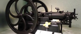
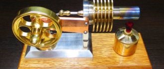
The first piston gasoline engine
Daimler Reitwagen motorcycle, sketch from 1885 patent
Meanwhile, Nikolaus Otto saw his motor only as a stationary one. But his comrade-in-arms, Gottlieb Daimler, actively campaigned for the boss to use internal combustion engines in transport. Otto was against it, so in 1880, taking Maybach with him, Daimler left Deutz AG.
The two engineers focused on a single task - to create a lightweight, sufficiently powerful piston engine suitable for installation on a wheeled chassis. The problem was that the engine of Otto's design ran on gas and required a gas generator. Daimler and Maybach decided to develop a liquid fuel motor in order to get rid of the massive converter. This was not a simple matter, since at that time there was no way to create an optimal fuel-air mixture on which the engine would operate stably. The solution to the problem was the evaporative carburetor developed by Maybach in 1885. The carburetor made it possible to build a gasoline internal combustion engine (Standuhr) with a volume of 100 cm3 and a power of 1 hp, which worked quite steadily and reliably. In the same year, a slightly reduced Standuhr with a power of 0.5 hp. placed on a wooden bicycle, thereby obtaining the world's first motorcycle. And a year later, a car.
The piston internal combustion engine has come a long way since then. However, its four-stroke operating principle remained unchanged. Today there are more than 1.2 billion cars in the world and most of them are equipped with internal combustion engines.
Operating principle of two-stroke and four-stroke piston engines.
| 4-stroke cycle of a piston internal combustion engine: 1. Suction of the combustible mixture. 2. Compression. 3. Working stroke. 4. Exhaust. | 2-stroke cycle of operation of a piston internal combustion engine: 1. The piston moves upward and the fuel mixture is compressed in the current cycle and the mixture for the next cycle is sucked into the cavity under the piston. 2. The piston lowers back - the working stroke, exhaust and displacement of the fuel mixture from under the piston into the working cavity of the cylinder. |
Number of cylinders in piston engines
may vary depending on the design (from 1 to 24). The engine volume is considered to be equal to the sum of the volumes of all cylinders, the capacity of which is found by multiplying the cross-section by the piston stroke.
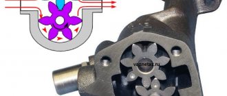
Operating principle of a rotary engine
The operating principle of a rotary piston engine once made many talented engineers raise their eyebrows in surprise. And today, the talented engineers of Mazda deserve all praise and approval. It's no joke, believe in the performance of a seemingly buried engine and give it a second life, and what a second life!
Sectional view of a rotary engine
Rotary motor rotor
Rotary engine chamber
The rotor has three convex sides, each of which acts as a piston. Each side of the rotor has a recess in it, which increases the speed of rotation of the rotor as a whole, providing more space for the air-fuel mixture. At the top of each face there is a metal plate, which forms the chambers in which the engine strokes occur. Two metal rings on each side of the rotor form the walls of these chambers. In the middle of the rotor there is a circle in which there are many teeth. They are connected to a drive, which is attached to the output shaft. This connection determines the path and direction that the rotor moves inside the chamber.
The engine chamber is approximately oval in shape (but to be more precise it is an Epitrochoid, which in turn is an elongated or shortened epicycloid, which is a flat curve formed by a fixed point on a circle rolling on another circle). The shape of the chamber is designed so that the three apexes of the rotor are always in contact with the chamber wall, forming three closed gas volumes. In each part of the chamber, one of four cycles occurs:
- Inlet
- Compression
- Combustion
- Release
The inlet and outlet openings are located in the walls of the chamber and there are no valves on them. The exhaust port is connected directly to the exhaust pipe, and the intake port is directly connected to the gas.
Rotary motor output shaft
The output shaft has semicircular cam protrusions placed asymmetrically relative to the center, which means that they are offset from the centerline of the shaft. Each rotor fits onto one of these lugs. The output shaft is analogous to the crankshaft in piston engines. Each rotor moves inside the chamber and pushes its own cam.
Since the cams are installed asymmetrically, the force with which the rotor presses on it creates a torque on the output shaft, causing it to rotate.
Structure of a rotary engine
A rotary engine consists of layers. The twin-rotor engine consists of five main layers, which are held together by long bolts arranged in a circle. Coolant flows through all parts of the structure.
How to polish a car yourself?
The two outer layers are closed and contain bearings for the output shaft. They are also sealed in the main sections of the chamber where the rotors are contained. The inner surface of these parts is very smooth and helps the rotors work. The fuel supply section is located at the end of each of these parts.
The next layer contains the rotor itself and the exhaust part.
The center consists of two fuel supply chambers, one for each rotor. It also separates the two rotors so its outer surface is very smooth.
At the center of each rotor are two large gears that rotate around smaller gears and are attached to the motor housing. This is the orbit for rotating the rotor.
Of course, if the rotary engine had no disadvantages, then it would definitely be used in modern cars. It is even possible that if the rotary engine had been sinless, we would not have known about the piston engine, because the rotary engine was created earlier. Then the human genius, trying to improve the unit, created a modern piston version of the engine.
But unfortunately, the rotary engine has disadvantages. Such obvious mistakes of this unit include the sealing of the combustion chamber. In particular, this is due to insufficiently good contact of the rotor itself with the cylinder walls. When friction with the cylinder walls, the metal of the rotor heats up and, as a result, expands. And the oval cylinder itself also heats up, and even worse - the heating occurs unevenly.
If the temperature in the combustion chamber is higher than in the intake/exhaust system, the cylinder must be made of high-tech material installed in different places in the body.
In order for such an engine to start, only two spark plugs are used. No longer recommended due to the nature of the combustion chamber. The RPD is equipped with a completely different combustion chamber and produces power three-quarters of the working time of the internal combustion engine, and the efficiency is as much as forty percent. In comparison: for a piston engine the same figure is 20%.
Compression of the working fluid:
• In diesel engines
, operating on diesel fuel or gas (with the addition of 5% diesel fuel), the air is compressed, and when the piston reaches the point of maximum compression, fuel is injected, which ignites from contact with heated air.
• Compression model engines
.
The fuel supply in them is exactly the same as in gasoline engines. Therefore, for their operation, a special fuel composition is required (with admixtures of air and diethyl ether), as well as precise adjustment of the compression ratio. Compressor engines have found their way into the aircraft and automotive industries. • Glow engines
.
The principle of their operation is in many ways similar to engines of the compression model, but they are not without design features. The role of ignition in them is performed by a glow plug, the glow of which is maintained by the energy of the fuel burned in the previous stroke. The composition of the fuel is also special, based on methanol, nitromethane and castor oil. Such engines are used in both cars and airplanes. • Calorizer engines
. In these engines, ignition occurs when fuel comes into contact with hot parts of the engine (usually the crown of the piston). Open hearth gas is used as fuel. They are used as drive motors in rolling mills.
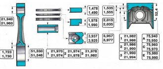
What is a piston in an internal combustion engine?
The design of the part includes three components:
These components are available both in solid-cast pistons (the most common option) and in composite parts.
Bottom
The bottom is the main working surface, since it, the walls of the liner and the head of the block form the combustion chamber in which the fuel mixture is burned.
The main parameter of the bottom is the shape, which depends on the type of internal combustion engine (ICE) and its design features.
Two-stroke engines use pistons with a spherical bottom - a protrusion of the bottom, this increases the efficiency of filling the combustion chamber with the mixture and removing exhaust gases.
In four-stroke gasoline engines, the bottom is flat or concave. Additionally, technical recesses are made on the surface - recesses for valve plates (eliminate the likelihood of a piston colliding with the valve), recesses to improve mixture formation.
In diesel engines, the recesses in the bottom are the largest and have different shapes. These recesses are called the piston combustion chamber and are designed to create turbulence as air and fuel enter the cylinder to ensure better mixing.
The sealing part is designed to install special rings (compression and oil scraper), the task of which is to eliminate the gap between the piston and the liner wall, preventing the breakthrough of working gases into the sub-piston space and lubricants into the combustion chamber (these factors reduce the efficiency of the motor). This ensures heat transfer from the piston to the liner.
Sealing part
The sealing part includes grooves in the cylindrical surface of the piston - grooves located behind the bottom, and bridges between the grooves. In two-stroke engines, special inserts are additionally placed in the grooves, into which the ring locks rest. These inserts are necessary to eliminate the possibility of the rings turning and their locks getting into the intake and exhaust windows, which can cause their destruction.
The bridge from the edge of the bottom to the first ring is called the fire belt. This belt takes on the greatest temperature impact, so its height is selected based on the operating conditions created inside the combustion chamber and the material used to make the piston.
The number of grooves made on the sealing part corresponds to the number of piston rings (and 2 - 6 of them can be used). The most common design is with three rings - two compression and one oil scraper.
In the groove under the oil scraper ring, holes are made to allow oil to drain, which is removed by the ring from the liner wall.
Together with the bottom, the sealing part forms the piston head.
You will also be interested in:
The skirt acts as a guide for the piston, preventing it from changing position relative to the cylinder and providing only reciprocating movement of the part. Thanks to this component, a movable connection is made between the piston and the connecting rod.
For connection, holes are made in the skirt to install the piston pin. To increase the strength at the point of contact of the finger, special massive bulges called bosses are made on the inside of the skirt.
To fix the pin in the piston, grooves for retaining rings are provided in the mounting holes for it.
Classification of cooling systems:
• Air CO
– transfer heat to the air due to the ribbed outer surface of the cylinders.
Either they are used on weak engines (tens of hp), or on powerful aircraft engines, which are cooled by a fast flow of air. • Liquid CO
– liquid (water, antifreeze or oil) is used as a coolant, which is pumped through the cooling jacket (channels in the walls of the cylinder block) and enters the cooling radiator, in which it is cooled by air flows, natural or from fans. Rarely, metallic sodium is also used as a coolant, which melts from the heat of a warming up engine.
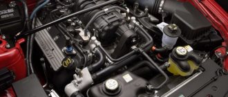
Application.
Piston engines, due to their power range (1 watt - 75,000 kW), have gained great popularity not only in the automotive industry, but also in aircraft construction and shipbuilding. They are also used to drive military, agricultural and construction equipment, electric generators, water pumps, chainsaws and other machines, both mobile and stationary.
See also:
- Volkswagen New Beetle
- Opel Ascona A
- Daewoo Lanos
- History of the road sign
- BMW E65-E66
- Airless tires
- BMW Z8