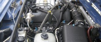
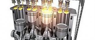
Synchronous operation of several cylinders
The operating principle of the internal combustion engine was described above, while processes in one cylinder were considered.
However, as you know, most engines are multi-cylinder. In order to achieve smooth and synchronous operation of all cylinders, the working stroke of the piston in each individual cylinder must occur after an equal period of time (the same angles of rotation of the crankshaft). In this case, the sequence with which identical strokes alternate in different cylinders is usually called the operating order of the internal combustion engine (for example, 1-2-4-3). In practice, this looks like this: after the working stroke in cylinder 1, then the working stroke occurs in the second, fourth, and only then in the third cylinder.
Depending on the engine layout and its design features, the sequence (order of operation) may be different. The fact is that engines are not only in-line, but also V-shaped.
In the second case, this arrangement allows the cylinders to be placed at an angle, making it possible to increase the total number of cylinders without increasing the length of the engine cylinder block itself. This solution allows you to place a powerful multi-cylinder internal combustion engine under the hood of not only a large SUV or truck, but also a passenger car.
CLAIM
What is the displacement of a car engine? One of the most important characteristics of any gasoline or diesel engine is its displacement.
Since the advent of the first internal combustion engines, this characteristic of the engine has been a primary indicator, according to 1. Internal combustion engine: a 5-stroke rotary engine with rotating shut-off elements, separate compression and expansion sections of the working fluid and separate combustion chambers of constant volume, containing a cylindrical rotor capable of rotating, equipped with blades, which is placed in a hollow body equipped with windows for gas exchange, having symmetrically placed cylindrical hollow sockets around the circumference of the inner surface of the body, the number equal to the number of rotor blades, where locking drums that can rotate are installed, in which the volumetric relationship of the outer cylindrical surface of the rotor and the annular the inner surface of the housing, as well as the surfaces of the rotor blades and locking drums, forms working chambers - “expansion” segments and “release” segments, which can change their volume, and have a drive from the main shaft through gear transmissions to the shafts of other rotating technological elements, different the fact that in the engine body there are separate compression sections with bladed rotors placed in them that can rotate, and the number of these compression sections is equal to the number of blades of the main working rotor and the number of locking drums; as well as on the engine body, hollow combustion chambers of constant volume are arranged, with a number twice the number of locking drums, while the volumes of the compression sections, combustion chambers and the volumes of the arc sectors of the main rotor section of the engine are mutually located so that they can communicate with each other through extremely short gas ducts with bypass windows that can be periodically unlocked and locked due to the action of cylindrical spool valves that can rotate, in a mode that ensures the sequential implementation of the full cycle of technological strokes of the internal combustion engine; at the same time, the mutual placement of the working agent bypass windows, the mode of their “unlocking-locking” by cylindrical spool valves that can rotate, as well as the interconnected correspondence of the angular positions of the main working rotor blades that can rotate, the rotor blades of the compression sections and the openings of the locking drums, as well as the adjustment of the moments sparks of the spark plugs are arranged so that the ignition and complete combustion of the compressed working mixture in the combustion chambers can occur in a locked and constant volume of these chambers with all the working fluid bypass windows closed, and the operating mode of each group of two combustion chambers for each expansion sector of the main rotor section is configured so that from two adjacent chambers that have the ability to eject working gases into the same expansion segment of the main rotor section, each successive “expansion” stroke only one of them has the ability to eject gases into the expansion sector, and such a sequential alternation mode connection between the combustion chambers in strokes of connection with the expansion segment of the main rotor section can be carried out in a translational sequence.
2. The engine according to claim 1, characterized in that the main working rotor and each of the rotors of the compression sections have common locking drums; in this case, the rotors and locking drums, tightly in contact with each other with cylindrical side surfaces, are able to rotate in accordance with such angular velocities that their cylindrical surfaces rotate in opposite directions with the same linear speed, that is, they contact the surfaces in the rolling mode without slipping and friction relative to each other each other, while the diameter of the locking drums has a size relative to the diameter of the cylindrical surface of the main rotor - as many times smaller as the number of passage openings in the drum is less than the number of blades on the main rotor (for example: 2 or 3 times), and the size of the diameter of the cylindrical part of the rotors of the compression sections is equal to the diameter of the locking drums, and the number of blades of the rotors of the compression sections is equal to the number of passage openings in the locking drum.
3. The engine according to claim 1, characterized in that the number of locking drums is equal to the number of blades on the main rotor and, if it is possible for the blades of the main rotor to pass through the passage openings of the locking drums, their surfaces do not touch each other, but pass without contact at the minimum possible distance between their nearby surfaces without friction.
Operating principle and main characteristics
External speed characteristic of diesel enginePost navigation
The operating cycle of an internal combustion engine (ICE) consists of a series of processes that increase the power of the engine acting on the crankshaft. The work cycle consists of several stages:
- the cylinder is filled with the fuel mixture;
- the mixture is compressed;
- the fuel mixture ignites;
- the gases expand and the cylinder is cleaned.
In an internal combustion engine, the piston moves in one direction (up or down). The crankshaft makes one revolution in two strokes. The working stroke of the piston is the one during which useful work is performed and the burnt gases expand.
Two-stroke engines are those in which the cycle is completed in one revolution of the crankshaft or in two strokes. Four-stroke units are characterized by completing a working cycle in two revolutions of the crankshaft or in four strokes.
Main characteristic indicators of a 4-stroke engine:
- Due to the movement of the working piston, gases are exchanged.
- The unit is equipped with a gas distribution mechanism that allows the cylinder cavity to be switched to inlet and outlet.
- An exchange of gases occurs at the moment of a separate half-turn of the crankshaft.
- Gear reducers and a belt chain drive make it possible to change the timing of gasoline injection, ignition and gas distribution mechanism drive in relation to the crankshaft speed.
How does a four stroke engine work?
Structurally, the working cycle of a typical four-stroke unit is ensured by the operation of the following elements:
- cylinder;
- piston - performs reciprocating movements inside the cylinder;
- intake valve - controls the process of supplying the air-fuel mixture to the combustion chamber;
- exhaust valve - controls the process of exhaust gases ejecting from the cylinder;
- spark plug - ignites the resulting air-fuel mixture;
- crankshaft;
- camshaft - controls the opening and closing of valves;
- belt or chain drive;
- crank mechanism - translates the movement of the piston into rotation of the crankshaft.
Read also: Gas burner for a roofing cylinder
Duty cycle of a four-stroke engine
The working cycle of such a mechanism consists of four cycles, during which the following processes are implemented:
- Intake (fuel and air injection). At the beginning of the cycle, the piston is at TDC. At the moment when the crankshaft begins to rotate, it acts on the piston and moves it to BDC. This leads to the formation of vacuum in the cylinder chamber. The camshaft acts on the intake valve, gradually opening it. When the piston is in its extreme position, the valve is completely open, resulting in intense injection of fuel and air into the cylinder chamber.
- Compression (increasing the pressure of the combustible mixture). In the second stage, the piston begins to move back to the top dead center of the compression stroke. The crankshaft makes another turn and both valves are completely closed. The internal pressure increases to 1.8 MPa and the temperature of the combustible mixture rises to 600 C°.
- Expansion (working stroke). When the piston reaches the top position in the combustion chamber, the maximum compression is set to 5 MPa and the spark plug is fired. This leads to combustion of the mixture and an increase in temperature to 2500 C°. Pressure and temperature lead to an intense impact on the piston, and it begins to move back to BDC. The crankshaft makes another turn, and thus the thermal energy is converted into useful work. The camshaft opens the exhaust valve, and when the piston reaches BDC, it is fully open. As a result, the exhaust gases begin to gradually leave the chamber, and the pressure and temperature decrease.
- Exhaust (removal of exhaust gases). The engine crankshaft turns and the piston begins to move to the top point. This leads to the expulsion of exhaust gases and an even greater decrease in temperature and a decrease in pressure to 0.1 MPa. Next, a new cycle begins, during which these processes are repeated again.
During each stroke, the engine crankshaft rotates 180°. During a full working cycle, the crankshaft rotates 720°.
The four-stroke engine has become widespread. It can work with both gasoline and diesel fuel. The difference between the operating cycle for a diesel engine is that the ignition of the air-fuel mixture does not occur from a spark, but from high pressure and temperature at the end point of the compression stroke.
Two stroke motor
What is urea for a diesel engine
An engine of this type operates on the Otto or Diesel cycle for the first 4 strokes, and then cooled air or water is supplied to the cylinder. Due to air expansion or water evaporation, additional cooling of the cylinder walls occurs and engine heat losses are reduced. In this case, there are two working strokes - one with fuel and the other with steam or air. This class of engines includes: the Bajulaz engine, created by the Swiss company Bajulaz; Crower engine, invented by Bruce Crower from the USA; and the six-stroke Velozeta engine, built at the Thiruvananthapuram Engineering College in India.
Compression stroke
Compression itself (increasing pressure in the cylinder) does not begin immediately after the piston begins to move upward. The fact is that the fuel-air mixture, with the intake valve open, continues to flow into the cylinder for some time, despite the beginning of the pressure increase. Therefore, the closing of the intake valve must be coordinated with the nature of the mixture flow at its plate.
From the point of view of the best filling of the cylinder (and, accordingly, the greatest power), at the moment the intake valve closes, the mixture at the valve should stop, i.e. at this moment there is neither direct flow through the valve - into the cylinder, nor reverse flow - out of the cylinder. Here the process is greatly influenced by the design of the intake system, rotation speed, and throttle position. In general, the higher the rotation speed and the opening of the throttle valve, the longer the intake valve should be delayed in closing, given a constant length of the intake duct.
In practice, as a rule, a compromise option is chosen, but there are designs with variable valve timing (at which the closing delay of the intake valve changes) and with variable length of the intake system channels, which improve cylinder filling and engine parameters in a wide range of modes. Compromise solutions usually lead to deterioration of engine parameters due to reverse ejection of the mixture at low speeds and “undercharging” of the cylinder (i.e., reducing the amount of incoming mixture relative to the maximum possible) at high speeds. Engines with multi-valve heads (with three or four valves per cylinder) have a smaller delay in valve closure compared to traditional designs. When the piston moves upward with the valves closed, the fuel-air mixture is compressed. In this case, the pressure in the cylinder depends on the leakage of the mixture through the piston rings and valves. Their wear or damage, as well as scratches and scratches on the cylinder surface also increase mixture leakage through the piston rings. Under the influence of friction and pressure in the cylinder, the piston rings are pressed against the lower surfaces of the grooves, and the sealing of the cylinder cavity above the piston is achieved on one side at the junction of the rings with the surface of the cylinders, and on the other - along the lower end surfaces of the rings and grooves.
Duty cycle of a four-stroke carburetor engine
The engine operating cycle is a series of sequential, periodically repeating processes in the cylinders, as a result of which the thermal energy of the fuel is converted into mechanical work.
The part of the working cycle completed during the movement of the piston from one dead center to another, i.e., during one stroke of the piston, is called a stroke. Engines whose operating cycle is completed in four piston strokes (two revolutions of the crankshaft) are called four-stroke.
In the combustion chamber (Fig. 2.1) of a carburetor engine, an intake 4
and exhaust
6
valves controlled by a gas distribution mechanism, and a spark plug 5.
The duty cycle of a carburetor four-stroke engine consists of successive strokes of intake, compression, expansion and exhaust.
Intake stroke. Let us assume that as a result of rotation of the crankshaft when starting the engine (manually or using a special electric
Intake Compression Expansion Exhaust
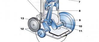
Rice. 2.1. Operating cycle of a single-cylinder four-stroke carburetor engine: / - piston; 2
— working mixture;
3
— inlet channel;
4
— inlet valve;
5 - spark plug; 6
— exhaust valve;
7 — exhaust channel; 8
— connecting rod;
9
- crankshaft
engine), the piston moves from TDC to BDC. In this case, the inlet valve 4
is open and outlet valve
6
is closed.
Since the volume of the cylinder increases when the piston moves down, the pressure above the piston decreases to 0.07-0.09 MPa. Intake channel 3
is connected to a special device - a carburetor, which prepares a combustible mixture of fuel and air. Due to the pressure difference between the carburetor and the cylinder, the combustible mixture enters the engine cylinder through the intake port and the open intake valve.
If the engine is already running, then the combustible mixture, entering the cylinder, mixes with residual gases (residual combustion products from the previous cycle) and forms a working mixture. In contact with residual gases and heated parts, the mixture is heated to a temperature of 75-125 °C.
Compression stroke. As the piston approaches BDC, the intake valve closes. When the piston moves from BDC to TDC, due to a reduction in cylinder volume with the valves closed, the pressure and temperature of the working mixture increase. At the end of the compression stroke, the pressure reaches 0.9–1.5 MPa, and the temperature reaches 270–480 °C. At this moment, a high voltage is supplied to the electrodes of the spark plug 5, which causes a spark discharge between them, as a result of which the working mixture ignites and burns. During the combustion of fuel, a large amount of heat is released, which causes the temperature of the gases (combustion products) to rise to 2200–2500 °C, and the pressure inside the cylinders reaches 3.0–4.5 MPa.
Expansion stroke (power stroke). Under the pressure of expanding gases, the piston moves from TDC to BDC (both valves are closed). Thermal energy is converted into useful work, which is why the piston stroke during the expansion stroke is called the power stroke.
When the piston moves to BDC, the volume of the cylinder increases, as a result of which the pressure decreases to 0.3–0.4 MPa, and the gas temperature decreases to 900–1200 °C.
Release stroke. When the piston reaches BDC, the exhaust valve opens 6,
and with further rotation of the crankshaft, the piston moves from BDC to TDC, pushing exhaust gases through the open valve, exhaust port 7 and exhaust pipe into the environment. By the end of the exhaust stroke, the pressure in the cylinder is 0.11–0.12 MPa, and the temperature is 600–900 °C.
As the piston approaches TDC, the exhaust valve closes, the intake valve opens, and a new operating cycle begins.
Engine operation
As already noted, the operation of a four-stroke engine consists of four strokes of the piston or two revolutions of the crankshaft.
- Inlet . The piston moves downward, opening the intake valve. From the carburetor the combustible mixture enters the cylinder. When the piston reaches the bottom position, the intake valve closes.
- Compression . The piston moves upward, causing the combustible mixture to compress. When it approaches the top point, the compressed gasoline ignites.
- Extension . Gasoline ignites and burns. As a result, the flammable gases are stretched and the piston moves downwards. In this case, two valves are closed.
- Release . The crankshaft continues to move around its axis by inertia, and the piston moves upward. At the same time, the exhaust valve opens and exhaust gases enter the pipe. When the valve passes the dead center, the intake valve closes.
Read also: What is Scart cable for?
Methods for purging cylinders
It is obvious that the purging process, a mechanism that qualifies as complex. Properly performed purging directly affects power and efficiency indicators. To improve performance, designers are constantly trying to improve and bring the process to perfection.
How to blow out a cylinder:
“Circuit” blowing. This type of blowing is simple and therefore widespread. The disadvantage is that the application is associated with excessive fuel consumption. Types of contour blowing: return-loop, deflector, high-altitude.
“U-shaped” purging. The “U-shaped” principle is to be used only on engines with two cylinders. When carrying out, one cylinder participates in the process of gas intake, the second releases waste. The effect of purging is felt in fuel efficiency; the process is accompanied by uneven heating of the steam responsible for the exhaust.
“Valve-slit” purge. It differs in that it requires a gas distribution mechanism to control the valves. The valve is used both to provide fuel and to remove exhaust vapors. Purge involves the removal of waste through a valve in the cylinder head and the flow of fuel through the holes. The advantage is that purge increases fuel efficiency and minimizes the toxicity of emitted vapors. Disadvantage, complexity of design and violation of regimes associated with an increase in the operating temperature of the unit.
“Direct flow” blowing. Used in power plants with the number of pistons equal to two. In this case, the cylinder is located in a horizontal position. The pistons move towards each other. While moving, each piston releases and closes the valve: one piston admits a portion of fuel, the second removes a portion of waste from the cylinder. The combustion chamber is formed when the pistons approach each other. The effect of this purge option is maximum: it removes burnt gases and saves fuel. Minus, a complex mechanism of cranks and connecting rods is required, engine temperature indicators require the use of coolers and resistant materials for the manufacture of parts.
Two-stroke engine 5 TDF with direct-flow purge
How does a two-stroke engine work?
It was mentioned above that piston engines are divided into both 4-stroke and 2-stroke. The operating principle of the latter is slightly different from what was described earlier. And the design of such a unit itself is much simpler than the previous design. In a two-stroke unit there are only two windows in the cylinder - inlet and outlet. The second is located slightly above the first, and what it is for will now be explained.
At the beginning of the first stroke, the piston, which previously blocked the inlet port, begins to move upward, as a result of which it blocks the fuel inlet port. At the same time, the piston continues to descend, which leads to compression of the working mixture. As soon as the part reaches the desired position, the first spark is formed on the candle, and the created mixture is immediately ignited, igniting. The inlet window is already opening at this point. It passes the next portion of fuel and air, continuing the operation of the mechanism.
The beginning of the second stroke is characterized by a change in the direction of movement of the piston - it begins to move downward. It is acted upon by gases that tend to expand the available space. The piston moves, opening the inlet window, and the gases remaining after combustion of the mixture escape, allowing a new portion of fuel inside.
Some of the working mixture also leaves the cylinder through the open exhaust valve. Therefore, it becomes clear why two-stroke engines require so much fuel.
Working cycle of a four-stroke diesel engine
Unlike a carburetor engine, air and fuel are introduced separately into the diesel cylinder.
Compression stroke
Both valves are closed. The piston moves from ground level. to v.m.t. (Figure b) and compresses the air. Due to the high compression ratio (about 14...18), the air temperature becomes higher than the auto-ignition temperature of the fuel.
At the end of the compression stroke, with the piston position close to TDC, liquid fuel begins to be injected into the cylinder through the nozzle. The nozzle design ensures fine atomization of fuel in compressed air.
Fuel injected into the cylinder is mixed with heated air and remaining gases to form a working mixture. Most of the fuel ignites and burns, the pressure and temperature of the gases increase.
Expansion stroke
Both valves are closed. The piston moves from T.M.T. to n.m.t. (Figure c). At the beginning of the expansion stroke, the rest of the fuel is burned.
Release stroke
The exhaust valve opens. The piston moves from ground level. to v.m.t. (Figure d) and through the open valve pushes the exhaust gases into the atmosphere.
Then the working cycle is repeated.
In the described engines, during the operating cycle, only during the expansion stroke, the piston moves under gas pressure and, through a connecting rod, drives the crankshaft into rotational motion. When performing the remaining strokes - exhaust, intake and compression - you need to move the piston by rotating the crankshaft. These strokes are preparatory and are carried out due to the kinetic energy accumulated by the flywheel during the expansion stroke. The flywheel, which has a significant mass, is mounted at the end of the crankshaft.
Compared to a carburetor engine, diesel has the following main advantages:
- per unit of work performed, an average of 20...25% (by weight) less fuel is consumed
- work on cheaper fuel, which is less fire hazardous
Disadvantages of diesel:
- higher gas pressure in the cylinder requires increased strength of parts, and this leads to an increase in the size and weight of the diesel engine
- starting it is difficult, especially in winter
The good economic performance of diesel engines has led to their widespread use as engines for tractors, trucks and cars.
Design Features
Diesel engines, of course, do not have such colossal differences as the Wankel rotary piston engine, the design of which is absolutely not similar to the “anatomy” of a traditional internal combustion engine, but it has a number of features that draw a line between it and gasoline engines.
The diesel engine also has a crank mechanism, but its compression ratio is significantly higher - 19-24 units versus 9-11 units, respectively. The fundamental difference between a diesel engine and a gasoline engine is how the fuel-air mixture is formed, ignites and burns.
A diesel internal combustion engine does not have spark plugs and, accordingly, ignition of the fuel-air mixture occurs from compression. At the same time, air and diesel fuel are supplied separately. It should also be noted that almost no modern diesel engine can do without a supercharging system, which is used to improve the performance of the unit. Variable geometry turbochargers are used to optimize boost over the widest possible speed range. A diesel unit has a higher efficiency, but it is heavier and produces more torque at low speeds than a gasoline internal combustion engine.
Read also: What is measured in microns
Features of a 4-stroke engine
In a two-stroke engine, lubrication of the piston and cylinder pins, crankshaft, piston, bearing and compressor rings is carried out by pouring oil into gasoline. The crankshaft of a 4-stroke engine is located in an oil bath, which is a significant difference. That is why there is no need to mix fuel and add oil. All the car owner needs to do is fill the fuel tank with gasoline.
The car owner, therefore, has no need to purchase special oil, without which a two-stroke engine cannot function. In addition, in the presence of a four-stroke engine, the amount of carbon deposits on the piston mirror and on the walls of the muffler is reduced
Another important difference is that in a two-stroke engine, a flammable mixture splashes into the exhaust pipe, which is due to its design
https://youtube.com/watch?v=Pby7ms9Smiw
It should be recognized that four-stroke engines also have minor disadvantages. For example, their working moments for regulating the thermal valve clearance are not particularly high-quality.
Creation of a two-stroke engine
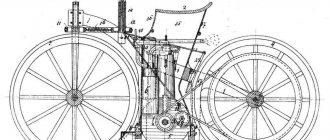
There are many speculations about who was the first to create an internal combustion engine. It is known for certain that the first two-stroke engine running on gas was invented and designed by the Belgian Jean Joseph Etienne Lenoir; this event occurred in 1858.
Lenoir engine (on display in the museum)
At that time, a steam engine had already been created, and the Belgian’s invention surpassed it in characteristics. The engine is much lighter, simpler, and consumes less fuel. Despite the advantages, the power plant had many shortcomings and was inferior in reliability. After Nicholas Otto presented a four-stroke engine, which at that time was thought out in more detail, the engine operating on the two-stroke principle was forgotten, and was not used anywhere for a long period of time.
During the Great Patriotic War, the power plant was installed on aircraft. In our region, motors are known for their use on moto equipment. Three-cylinder units performing two strokes are used on motorcycles from Suzuki and Kawasaki. Today, engines are used in aviation; the leader here is the Austrian company Rotax, which produces engines for use on small aircraft.
Rotax 582 UL two-stroke twin-cylinder engine
After stricter requirements for environmental standards and emissions, the two-stroke engine was no longer used for installation in classic automobile vehicles. However, on light equipment such as scooters, snowmobiles, boats, replacing a small and light unit is not easy. Here the two-stroke unit simply has no competitors.
Diesel engines
It would seem that everything that could be imagined has already been created. But the talented inventor from Germany Rudolf Diesel did not think so. He was interested in how he could further change and improve Otto's principle. As a result of his work, another engine appeared, which is still used everywhere today, especially in trucks.
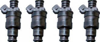
What is the operating principle of a diesel engine? In such engines, diesel fuel, or diesel fuel as it is also called, is injected at the right time under pressure. As a result, a combustible mixture is formed directly in the engine, where particles of compressed fuel combine with air and combustion occurs under pressure.
You can see how an internal combustion engine works here:
You can also read on this topic:
New car up to 800,000 rubles: review of several models
The price of a carburetor for a VAZ 2109 remains within 5,000 rubles
Honda Accord Tuning Basics
What to do if the idle speed of a VAZ 2109 (carburetor) fluctuates?
Solex 21083 carburetor: malfunctions and repairs
Share on social networks
Alex S October 8, 2013
Published in: Useful tips and car devices
Tags: How a car works