According to the design of disc brake mechanisms, they are divided into open and closed, single and multi-disc, and depending on the design of the disc, mechanisms with solid and ventilated, metal and bimetallic discs are distinguished.
The simplest, solid disc is used in cases where active cooling of the disc brake is possible. The ventilated disk is made in the form of a turbine impeller.
According to the method of fastening the caliper, disc brake mechanisms with a fixed and floating caliper are distinguished.
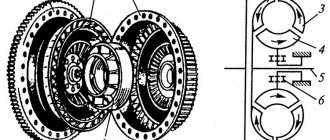
Rice. Disc brake: a - general view; b - cross section; 1 — brake disc; 2 - casing; 3 — brake pads; 4 — caliper; 5 - tube; 6 — air removal valve; 7 — working brake cylinder; 8 — movable pistons; 9 - sealing ring; 10 — rubber cuff; 11 — friction linings
Fixed caliper disc brake provides high drive force and increased rigidity. In a disc brake, the rotating part is the brake disc 7, usually made of cast iron and rigidly attached to the wheel hub. Brake pads 3 with friction linings 11, installed in a protective caliper 4 attached to a fixed suspension strut, are pressed against the disc on both sides. Inside the caliper, 7 cylinders with pistons are installed in special grooves, pressing the brake pads to the disc at the moment of braking. Under the influence of friction forces, the rotation of the disk stops, and the wheels of the car stop. The brake disc is covered from the outside by a wheel disc, and from the inside by a protective stamped casing 2.
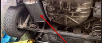
Disc brakes are installed on some truck models on the front wheels. To control such brakes, a hydraulic drive is mainly used. Brake fluid is supplied to the brake cylinder cavity through pipes from the master brake cylinder. To connect the brake cylinders located on both sides of the disc and equalize the pressure of the brake fluid, tube 5 is used. The brake pads move in the axial direction on special fingers that serve as guides.
Oil disc brakes are widely used in transmissions of modern tracked vehicles.
Operating principle of the hydraulic brake system
The hydraulic braking mechanism operates in the following order:
- When the pedal is pressed, mechanical force is transmitted to the GTZ piston.
- When moving inside the master cylinder, the piston creates increased fluid pressure in the hoses (tubes), moving inside which the liquid enters the wheel cylinders.
- The pistons begin to move when the fluid entering the cylinders puts pressure on them. In turn, they act on the pads, as a result of which, depending on the type of system, they move, squeezing on both sides and blocking the brake disc, or move apart, expanding the drum from the inside.
- Brake bars, coming into close contact with the surface of the disc (drum), slow down the movement of the wheel. Thus, the car can reduce speed to the desired limit or come to a complete stop.
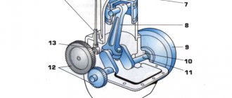
1 — brake disc; 2 — front wheel brake caliper; 3 - front contour; 4 — main brake cylinder; 5 — reservoir with a sensor for emergency drop in brake fluid level; 6 — vacuum booster; 7 — pusher; 8 — brake pedal; 9 — brake light switch; 10 — brake pads of the rear wheels; 11 — brake cylinder of the rear wheels; 12 - rear contour; 13 — rear axle axle housing; 14 — load spring; 15 — pressure regulator; 16 — rear cables; 17 — equalizer; 18 — front (central) cable; 19 — parking brake lever; 20 — alarm indicator for emergency drop in brake fluid level; 21 — parking brake warning switch; 22 — brake pads of the front wheels
Recommended: Estimated Engine Parameters
All this happens when the driver presses the pedal, applying physical force to the brake. When the foot is removed from the pedal, the fluid pressure inside the mechanism is equalized, after which the GTZ piston returns to its place. Return springs, acting on the pads, remove them from the surface of the disc (from the walls of the drum).
The simplest hydraulic drive includes:
- Brake pedal.
- Master cylinder (GTC).
- Wheel cylinders.
- Hoses and tubes.
- Pressure regulator (PR).
- Vacuum booster (not available on all systems).
The GTZ in different machines may differ slightly in design, but the principle of operation is always the same. The brake fluid reservoir is connected to the main line, due to which the following are constantly compensated during operation of the brake mechanism:
- Leakage of liquid composition through cylinder seals.
- Increasing the volume of wheel cylinders when wearing friction linings on the pads.
- Expansion of the fluid as a result of heating.
Brake control loops can be diagonal or parallel, they are separated by a GTZ. Thanks to this scheme, the braking system does not lose its functionality even if one of the circuits fails. This contributes to reliable operation of the mechanism and safe driving.
Pressure regulator
The purpose of this part is to reduce the pressure in the rear wheel cylinders during fast braking. The fact is that when the driver intensively presses the brake pedal, the force of inertia is activated, due to which the mass, and therefore the center of gravity of the car, moves forward, and the wheels located on the rear axle are instantly unloaded. This can cause a skid, and the regulator redistributes the pressure to prevent the rear wheels from losing contact with the road surface.
1 — brake pressure regulator housing; 2 - piston; 3 — protective cap; 4, 8 — retaining rings; 5 — piston sleeve; 6 — piston spring; 7 — body bushing; 9, 22 — support washers; 10 — sealing rings of the pusher; 11 — support plate; 12 — pusher bushing spring; 13 — sealing ring of the valve seat; 14 — valve seat; 15 - sealing gasket; 16 - plug; 17 — valve spring; 18 - valve; 19 — pusher bushing; 20 — pusher; 21 — piston head seal; 23 — piston rod seal; 24 - plug; A, D - chambers connected to the main cylinder; B, C - chambers connected to the wheel cylinders of the rear brakes; K, M, N - gaps; E - drainage hole
Vacuum brake booster (VUT)
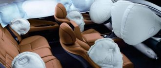
This element is responsible for increasing the pressure of the working fluid in the braking mechanism. As a rule, it is included in a common module with the GTZ. The VUT includes a circular chamber, which is internally divided into 2 parts by means of an elastic diaphragm. One of the parts of the chamber is connected to the intake manifold of the power unit using a valve. A vacuum is created there, while the second part communicates with the atmosphere. Pressing the pedal increases the pressure, which transfers vacuum to the GTZ piston. As a result, the force with which the braking system bars are pressed against the surface of the disc (drum) increases significantly.
Vacuum amplifier: 1 – tip mounting flange; 2 – rod; 3 – diaphragm return spring; 4 – sealing ring of the master cylinder flange; 5 – main cylinder; 6 – amplifier pin; 7 – amplifier housing; 8 – diaphragm; 9 – amplifier housing cover; 10 – piston; 11 – protective cover of the valve body; 12 – pusher; 13 – pusher return spring; 14 – valve spring; 15 – valve; 16 – rod buffer; 17 – valve body; A – vacuum chamber; B – atmospheric chamber; C, D – channels
Working principle of the parking brake
It is a purely mechanical device. It is activated by raising the handbrake lever to a vertical position until the latch clicks. In this case, tension occurs on two metal cables running under the bottom of the car, which tightly press the brake pads of the rear wheels to the drums.
To release the car from the parking brake, press the locking button with your finger and lower the lever down to its original position.
Don't forget to check the position of the handbrake before you start driving! Driving with the handbrake not released will quickly damage the brake pads.
Classification of brake systems
Modern cars are equipped with the following types of braking systems:
● working system;
● parking;
● auxiliary system;
We recommend: Features, advantages and disadvantages of low-profile car tires
● spare.
Service brake system
The service brake system is the main one and, accordingly, the most effective. Serves to reduce speed and stop. It is activated when the driver presses pedal , then the mechanism of compression (disc type brakes) or release (drum type brakes) of the brake pads of the brake mechanisms of all wheels is driven simultaneously.
Parking brake
The parking brake system is used to ensure that the vehicle remains stationary during long-term parking. Many drivers fix the car by engaging first or reverse gear. True, on a steep slope this measure may not be enough.
The parking brake is also used for starting off on a section of road with a slope. In this case, the right foot is on the gas pedal and the left foot is on the clutch pedal. Smoothly releasing the handbrake, engage the clutch and at the same time add gas, this prevents rolling downhill.
Spare brake system
A spare brake system was developed to protect the main working one in case of failure. It can be implemented as a stand-alone device, but most often it is implemented as one of the circuits of the main system.
Assistance system
An auxiliary braking system is mainly equipped with heavy-duty vehicles such as KamAZ, MAZ, and, of course, all foreign-made trucks. Auxiliary systems reduce the load from the main one during prolonged braking, for example, in mountainous and hilly areas.
For example, the so-called mountain brake. Braking occurs by the engine when the car is moving in gear. Its principle is that for a short time, special flaps close the inlet and outlet pipes, and the fuel for engine operation is also stopped. A vacuum is created in the cylinders and the engine begins to impede the movement of the car, thereby slowing it down.
Hydraulic brake drive
Hydraulic drives for brake mechanisms appeared somewhat later than mechanical drives, around 1910 - 1915. In the mass automotive industry, hydraulic brake drives have been used since 1924 thanks to the developments of engineers from the American automobile manufacturer (Chrysler Group LLC). In their work, such drives use hydrostatic laws, transferring energy to fluid under pressure. The principle of operation of a hydrostatic drive is based on the property of a liquid to maintain its volume under external pressure (negligible compressibility), as well as the ability to transmit the pressure created at any point equally to all points of a closed volume of liquid (Pascal’s law).
The hydraulic drive is widely used as a drive for the service brake system of passenger cars, light and medium-duty trucks, and light-duty buses.
***
Advantages and disadvantages of hydraulic brakes
The hydraulic drive of brake mechanisms has a number of significant advantages over other types of drive:
- simultaneous braking of all wheels (in principle) and the required distribution of braking forces between individual wheels (differentiation of braking forces);
- high efficiency - 0.9 and higher at normal coolant temperature (for comparison, the efficiency of a mechanical drive rarely exceeds 0.6);
- short response time (0.05...0.2 sec). Due to this property, due to the negligible compressibility of the liquid, the hydraulic drive has an undeniable advantage over the pneumatic drive, which has a response time of approximately ten times longer;
- relatively small dimensions and weight of instruments and devices used in the hydraulic drive;
- simplicity of design and ease of layout (hydraulic drive tubes can be laid any way and anywhere in the body or other structural elements of the car - this will not affect the performance of the drive).
Hydraulic brake drives are not without some significant disadvantages:
- impossibility of obtaining a large drive gear ratio. As is known, the transmission ratio of hydrostatic systems can be determined by the ratio of the cross-sectional areas of the pistons of the force-transmitting and force-receiving hydraulic cylinders (or elements replacing them). Obviously, a significant increase in the drive gear ratio to increase the braking force leads to a significant increase in the stroke of the control element (brake pedal or lever);
- failure due to local damage to any of the structural elements (tube, fitting, etc.), i.e. relatively low reliability of the drive. To eliminate this drawback, multi-circuit drives are used;
- the impossibility of prolonged and the danger of excessively intense braking. Prolonged braking can cause overheating and even boiling of the brake fluid due to heating of the structural elements of the brake mechanisms (pads, drums, etc.). Intensive braking with excessive force can lead to damage to the sealing elements, which, in turn, will lead to depressurization of the drive and loss of its functionality;
- high sensitivity to air entering the drive, sharply reducing its performance (and even leading to complete failure) when the system becomes airy;
- dependence of the drive efficiency on the temperature of the brake fluid (at low temperatures, the efficiency of the hydraulic drive decreases sharply due to an increase in the viscosity of the fluid);
- use as a working fluid of special liquids that can cause harm to the environment, animals and humans when released onto the soil and into the external environment.
***
Servicing brake discs and pads
Wear and replacement of discs
Brake disc wear is directly related to the driver's driving style. The degree of wear is determined not only by mileage, but also by driving on bad roads. Also, the degree of wear of brake discs is affected by their quality.
The minimum allowable thickness of a brake disc depends on the make and model of the vehicle.
The average value of the minimum permissible thickness of the front brake disc is 22-25 mm, rear – 7-10 mm. It depends on the weight and power of the car.
The main factors indicating that the front or rear brake discs need to be replaced are:
- disc beating when braking;
- mechanical damage;
- increase in braking distance;
- decrease in the level of working fluid.
Wear and replacement of pads
Brake pad wear primarily depends on the quality of the friction material. Driving style also plays an important role. The more intense the braking, the greater the wear.
The front pads wear out faster than the rear ones due to the fact that they experience the main load during braking. When replacing pads, it is better to change them at the same time on both wheels, be it rear or front.
Pads installed on one axle can also wear unevenly. This depends on the health of the working cylinders. If the latter are faulty, then they compress the pads unevenly. A difference in the thickness of the linings of 1.5-2 mm may indicate uneven wear of the pads.
There are several ways to determine whether your brake pads need to be replaced:
- Visual, based on checking the thickness of the friction lining. Wear is indicated by a lining thickness of 2-3 mm.
- Mechanical, in which the pads are equipped with special metal plates. As the linings wear out, the latter begin to come into contact with the brake discs, which causes disc brakes to squeak. The reason for squeaking brakes is abrasion of the lining up to 2-2.5 mm.
- Electronic, which uses pads with a wear sensor. As soon as the friction lining wears down to the sensor, its core comes into contact with the brake disc, the electrical circuit is closed and the indicator on the dashboard lights up.
Chemical composition of brake fluid, how to choose brake fluid based on its chemical composition?
Glycols. Most brake fluids are based on various glycol compounds (dihydric alcohols). Although these compounds are used to produce brake fluids that meet the requirements of the DOT 3 standard, their exceeded hygroscopic properties cause relatively high moisture absorption, accompanied by a decrease in the boiling point of the brake fluid. Provided that the free hydroxyls are partially bound by esters with boric acid. >a high-quality brake fluid DOT 4 (or “DOT 4+”, Super DOT 4) is created, which, when interacting with moisture, completely neutralizes it. Since the boiling point of DOT 4 brake fluid decreases much more slowly during its operation compared to DOT 3 fluid, service life is extended.
Fluids based on mineral oils (ISO 7308). The advantage of brake fluids based on mineral oils. is their lack of hygroscopicity, therefore the boiling point (in the absence of moisture absorption does not decrease. Mineral and synthetic oils for brake fluids are selected with special care. To ensure the least possible dependence of viscosity on temperature, special additives are added to the brake fluid.
The oil industry, in addition to fuels, also supplies brake fluids with various additives that improve their properties. It should be noted that it is not recommended to add brake fluids based on mineral oils (or vice versa) to brake systems in which glycols are used as brake fluid in order to prevent swelling of the elastomers.
Silicone fluids (SAE J 1705). Since silicone fluids, like mineral oils, do not absorb moisture, they are in some cases successfully used as brake fluid. The disadvantages of silicone fluids are significantly higher compressibility and worse lubrication properties, which limits their use as a working fluid in many hydraulic systems,
Braking mechanism design
The brake system on modern cars may include 3 or 4 circuits that perform different tasks. These include:
- Basic.
- Duplicate.
- Parking (manual, mountain).
- Auxiliary.
Working system
The main role among the listed systems is played by the main (working) one. It is used directly while driving and is designed to slow the vehicle down (if necessary) to a complete stop. There are two types of working systems:
- Disk.
- Drum.
We recommend: Cruise control in a car - what is it and how does it work?
Special pads in mechanisms of the first type, when pressing the pedal, compress the disk on both sides, preventing it from rotating and stopping the wheel. In systems of the second type, the pads are installed inside the wheel drum. When you press on the pedal, they expand it, preventing the wheel from rotating.
Backup brake
The backup mechanism plays a safety role, coming into operation if the main one fails. On some models it completely duplicates the rear as well as front brakes, on others its action is distributed only to one of the parts (most often to the rear cylinders). Sometimes this function is assigned to the handbrake.
Parking mechanism
The parking (mountain, hand) brake is designed to ensure the stability of the machine in the parking area. By releasing the brake pedal, the driver disables the main system. If the area chosen for stopping has even a slight slope, the car can easily roll and will not stop until it hits something in the way. The “something” could be another car, the side of a building, or a tree, and damage is virtually guaranteed. An additional function of the handbrake is to hold the car on a slope if it stalls during an ascent. In this case, in order to move off, the driver smoothly releases the clutch while simultaneously pressing the accelerator and lowering the exhaust brake lever. If these actions are performed simultaneously, the car will not roll back.
Handbrake drive VAZ 2106: 1 - cover; 2 — front cable; 3 - lever; 4 — button; 5 — thrust spring; 6 — latch rod; 7 — bushing; 8 - roller; 9 — rear cable guide; 10 — spacer sleeve; 11 — tension spring; 12 — rear cable; 13 — rear cable bracket
Assistance system
Auxiliary brake mechanisms are installed on large and heavy vehicles used to transport various cargo over long distances. They allow you to partially relieve the main system when the car is slowed down for a sufficiently long time on roads passing through hills or located in the mountains.
Main purpose of the system
Auxiliary braking system
Gradually accelerating when driving on downhill slopes, the car can pick up a fairly high speed, which may be unsafe for further movement. The driver is forced to constantly control speed through the use of. Such cycles of repeated braking lead to rapid wear of the brake linings and tires, as well as an increase in the operating temperature of the brake mechanism.
As a result, the coefficient of friction between the linings and the brake drum or disc is reduced, which leads to a decrease in the efficiency of the entire braking mechanism. And therefore the braking distance of the car increases.
To ensure long-term downhill driving at a low fixed speed and without overheating the brakes, an auxiliary braking system is used. It cannot reduce the speed of the car to zero. This is done by the working brake system, which in a “cold” state is ready to perform its task with the greatest efficiency at the right time.
Types of brakes
Most cars are equipped with friction-type mechanisms that use the principle of friction forces. They are located in the wheel and according to their design they are divided into drum and disk.
Previously, drum mechanisms were installed on the rear wheels, and disc mechanisms on the front. Now they can install the same types on all axes - both drum and disc.
Drums
Drum type or in everyday life - the drum mechanism consists of two shoes, a cylinder and a tension spring, which are installed on a platform in the brake drum.
Friction linings are glued to the pads (they can also be riveted).
The lower part of the pads is hinged on the supports, and the upper part is supported by a tension spring against the pistons of the wheel cylinders.
In unbraked mode, there is a gap between the block and the drum, which ensures free rotation of the wheels.
When fluid enters the cylinder, the pistons move apart and move apart the pads that come into contact with the drum, and brake the wheels. It is known that in this design the front and rear pads wear unevenly.
Disk
Disc version includes:
● a caliper mounted on a suspension; its body contains internal and external brake cylinders (there is an option with one cylinder) and a pair of pads;
● disk mounted on the hub.
When braking, the pistons press the pads against the rotating disc and stop it.
Operating principle and design of brakes
//www.youtube.com/watch?v=Av-jj8NNrv8
Let's look at the principle of operation of hydraulic brakes:
- The driver presses the pedal, which sets the piston in the master cylinder in motion. The brake booster is automatically activated, reducing the load on the brake pedal;
- The fluid transmits pressure through pipelines to the brake mechanisms, which create resistance to wheel rotation - braking occurs;
- When you remove your foot from the pedal, the return spring pulls the piston back, as a result of which the pressure decreases, the released fluid is sent back to the master cylinder - the wheels are released.
Hydraulic brake system
- high pressure brake hoses;
- brake pedal;
- working brake cylinders of front and rear wheels;
- vacuum brake booster;
- pipelines;
- master brake cylinder with reservoir.
- circuit, right rear - left front brake mechanisms;
- alarm sensor
- circuit left rear - right front brake mechanisms;
- master cylinder brake fluid reservoir;
- master brake cylinder
- vacuum brake booster
- brake pedal
- pressure regulator between circuits
- brake cable, parking
- brake mechanism - rear wheel
- parking brake adjuster
- parking brake lever
- front wheel brake mechanism
Mechanical brake system
Mechanical - in the parking brake system. Although the latest models also use an electric drive, then it is called an electromechanical handbrake.
For smooth and safe operation of the brakes, modern cars are equipped with all kinds of electronic units that improve their performance: ABS, emergency brake booster, brake force distribution unit.
Pneumatic brake system
The pneumatic drive is mainly used on heavy-duty vehicles.
The difference between this system and the hydraulic system is that instead of brake fluid, air works in the system. Air pressure opens the brake pads, and the air pressure in the system is provided by a special compressor operating from the engine through a belt drive.
Combined drive
A combined drive is a combination of several types of braking systems. For example, combining a hydraulic drive with an air drive, electric and pneumatic, there are others.
Shimano brake bleeding process
Car brake system
1. Fill the first syringe with fluid to bleed the brakes. Cut a small piece from the dropper and connect it to the syringe. Fill the tube with mineral oil and attach it to the fitting on the brake caliper. (Try to avoid any air bubbles in the syringe and tubing)
Syringe with mineral oil before connecting to the brake calliper. I had air there at the tip of the tube, which I later squeezed out and filled with oil.
2. Next, we use the second syringe, which is inserted into the handle. We remove the piston from it. You need to take the tip with the needle and remove (cut) the needle (I did this with pliers). This tip must be put on the syringe and screwed in instead of the plug; the plastic from the needle must be tightly screwed into the hole along the thread and not leak. Next we need to pour some oil into this syringe.
I begin to screw the syringe into the brake lever. The syringe should screw well into the threads and fit tightly. This is what came out after screwing in the syringe.
3. Now we need to unscrew the inlet nipple on the brake machine so that fluid flows from the first syringe into the hydraulic system. We press on the piston and drive the liquid through the hydraulic line into the syringe at the top.
The photo shows the border between Szyman's oil (red) and my Febi oil (green). This means there is new mineral water in the entire hydraulic line.
At this time, I recommend tapping your fingers or some object along the entire hydraulic line. This way we will definitely get rid of the remaining air bubbles.
I recommend securing the syringe with a tie in the position as in the photo so that the air that is in the system comes out to the top and does not fall back into the hydraulic line when the piston is pressed.
We press until a little oil remains in the first syringe - this means that you have definitely squeezed out all the air from the system.
Since I took a full syringe of mineral oil, I still have 1/3 left.
We tighten the inlet nipple to which the dropper was connected and put the syringe back in place.
4. At this stage we need to make sure that there are no bubbles left in the system. We begin to actively press on the handle and see if air comes out of our syringe installed in the brake handle. I also recommend taking a hexagon and changing the position of the handle (put it a little higher and apply the brake, then a little lower and apply the brake). Once you are sure that no more bubbles are coming out, you can move on to step 5.
5. Now insert the plunger into the second syringe and carefully unscrew it from the handle (this is necessary so as not to spill everything on the bicycle and the floor). Next, quickly tighten the plug and place the brake lever in a comfortable position.
Congratulations! Your brakes are pumped! Now all that remains is to test them in combat conditions! Good luck!
Video showing the process of bleeding Shimano brakes using a special tool:
(Visited 11,790 times, 1 visits today)
Overview of rim brakes
Classification, design and operating principle of engine timing
Usually, when something new appears, the old fades into the background and is gradually forgotten. This is not the case with rim bicycle brakes. Despite the emergence of a worthy alternative in the form of disc mechanisms, rim V-brake did not become part of history.
V-brake rim brakes
Advantages of rim brakes
- The braking force has sufficient power, which is enough for movement within the city and beyond.
- The cost is attractive and affordable, so there is no need to look for cheaper, and therefore lower quality, copies.
- The simple design does not create any difficulties during setup, which any amateur can handle. To set up, you will need a hexagon, a screwdriver, and a minimum of knowledge and time. In addition, in the absence of complex and expensive parts, the likelihood of breakdown is minimal.
- The minimum weight is an important advantage that makes a decisive difference for many cyclists.
- They do not create difficulties when transporting the bike.
The benefits are serious, which is why V-brake remains popular. But not everything is so smooth with these brakes. They also have disadvantages.
Bike with v-brake
Disadvantages of rim brakes
- During the braking process, the rim is used and its surface should be, although not perfect, relatively flat. If there are eights on the wheel, then you will need to increase the distance between the pads, correct deficiencies or change the wheel. Otherwise, the brake lever travel will be increased, which may cause a decrease in braking power.
- Using such a mechanism in severe bad weather turns out to be complicated or even impossible. We are not talking about light rain, but about specific dirt that sticks to the wheels. Although no one will undertake to drive on such roads, and therefore the use of the brake becomes irrelevant.
- Dirt and dust contribute to severe wear of the pads. When going on a bike ride to the mountains, you even need to take spare pads with you. In this case, cartridge options will be more relevant, which allow replacing not the entire pad, but only the brake lining.
- Frequent adjustments required. This is facilitated by abrasion of the pads, bending of the rim and knocking down the degree of rebound.
Many companies produce rim brakes, but good models can be found in the range of Avid and Shimano. V-break hydraulics deserve a special mention. Installation of such brakes takes place only on the trail.
Disc brakes on a bicycle
Disc brakes are gaining more and more popularity day by day. They can be front and rear, mechanical and hydraulic. The way a disc brake is designed makes this type of design highly sought after.
The steel disc, or rotor, is placed on the hub, usually on the left side. The caliper, the device that compresses the rotor with the brake pads, is also attached to the hub. The braking force is transmitted using a cable or hydraulic line coming from the brake lever on the steering wheel.
1. Mechanical disc brakes. This design uses the same cable as, for example, in “V-breaks”. The simplicity of the engineering solution explains the pros and cons of this design for the front brakes of a bicycle.
Minuses:
- frequent stretching and jamming of the cable;
- a large number of rubbing parts, and, as a result, the need for frequent replacement of components;
- the level of modulation is worse than in hydraulics.
Advantages:
- the possibility of repairs “on the knee” due to the simplicity of the design of bicycle disc brakes;
- relatively low price.
2. Hybrid disc brakes. Their operating scheme combines the principles of mechanics and hydraulics. In more detail, the braking force is transmitted to the hydraulic part of the brake using a cable.
This type is not very common: it is believed that its advantages in relation to pure mechanics are not great enough compared to the difference in price.
3. Hydraulic disc brakes. A disc brake consists of a means of transmitting braking force and the brake itself. The braking force is transmitted through a special high-pressure pipe. Pushing the handle causes the brake master cylinder to push down on the fluid in the tube, which transfers pressure to the brake cylinder in the caliper.
Minuses:
- high possibility of leakage;
- high price;
- complexity of repair and setup;
- heavy weight.
Pros:
- high efficiency when properly configured;
- the transmission of braking force is practically unchanged, that is, excellent modulation.
The way hydraulic brakes on a bike are designed makes them the best choice for high-end mountain bikes.