Purpose and principle of operation of the ABS sensor
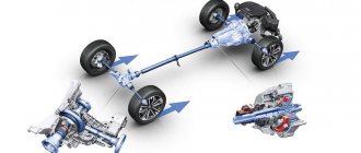
Anti-lock braking systems appeared on cars in the 70s, significantly increasing their safety during emergency braking. ABS consists of a control unit, a hydraulic unit, wheel brakes and speed sensors. The main device of the system is the control unit, into which sensor signals are received and processed. The data is analyzed and a decision is made to slow down or accelerate the wheels in the form of a signal to the valves of the hydraulic unit, which acts as a control.
When you press the brake pedal hard, the sensor detects that the wheel is locked and sends a signal to reduce the braking force, after which the brake fluid pressure drops and the wheel unlocks. If the brake pads are not released, the process will be repeated until the desired result is achieved. Thus, the operation of ABS is a cycle: braking - analysis - braking. The sensor itself controls the speed of rotation of the wheel.
The system is activated instantly, even before the wheel locks, which is indicated by the receipt of a signal on the instrument panel and is felt by characteristic shocks in the brake pedal. If a breakdown occurs, the brake system remains operational and operates normally.
Signs of a malfunctioning ABS sensor
The first sign of an ABS malfunction is a lit indicator on the instrument panel that does not go out for more than 6 seconds after turning on the ignition, or does not turn on when driving. A system breakdown is detected when the vehicle is moving at a speed of more than 25 km/h. There are quite a few problems that can happen with the anti-lock braking system, but the most common ones include the following:
- ABS sensor wire is broken or the controller unit is damaged. In this case, an error is displayed on the instrument panel, the system is turned off, and signals about changes in angular velocities are not given.
- The wheel sensor of the system has failed. When turned on, the system performs self-diagnosis and detects an error, but continues to function. The cause of the breakdown may be oxidation of the contacts, poor power supply to the sensor and a short circuit to ground.
- Receipt from an additional device of information about different angular speeds of wheels at different tire pressures or different tread patterns, when the wheels brake differently.
- Mechanical failure of elements - hub bearings, play and fracture of the rotor on the wheel sensor. In case of such failures, the system does not start. This also includes ABS pump failure.
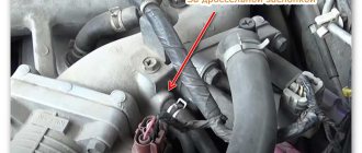
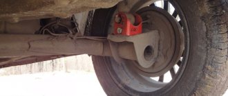
The most vulnerable element of the system is the wheel sensor, which is located next to the rotating hub and axle shaft. Exposure to dirt and play in the hub bearings can damage the device, completely blocking the operation of the ABS. Along with the indicator signal on the instrument panel, the following signs indicate a sensor failure:
- The on-board computer displays an ABS system error code.
- There is no characteristic vibration or sound when pressing the brake pedal.
- The wheels lock during emergency braking.
- Appearance of the parking brake signal when it is disabled.
Causes and symptoms of malfunctions
In new generation cars, when the ignition is turned on, automatic self-diagnosis of the anti-lock braking system occurs, during which the performance of all its elements is assessed.
Self-diagnosis shows an error. ABS is disabled.
Incorrect operation of the control unit.
Broken wire from the sensor to the control unit.
Diagnostics does not detect errors. ABS is disabled.
Violation of the integrity of the wiring from the control unit to the sensor (break, short circuit, oxidation).
Self-diagnosis gives an error. ABS works without turning off.
Broken wire of one of the sensors.
ABS does not turn on.
Break in the power supply wire of the control unit.
Chips and fractures of the impulse ring.
Large play on a worn hub bearing.
In addition to the display of indicator lights on the dashboard, there are the following signs of a malfunction of the ABS system:
- When applying pressure to the brake pedal, there is no reverse knocking or vibration of the pedal;
- During emergency braking, all wheels are blocked;
- The speedometer needle shows a speed less than the actual speed or does not move at all;
- If more than two gauges fail, the parking brake indicator on the dashboard lights up.
Checking the ABS sensor
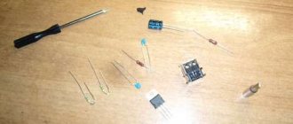
If the ABS sensor malfunctions, the control unit stops receiving commands and the system stops working, which is determined by the wheels locking when braking. Possible malfunctions of the device are determined by the tester. To do this, you need the tester itself, a soldering iron and pins for repairs. The pins are connected to the connectors, and the device measures the resistance of the ABS sensor, which must correspond to the parameters specified in the operating manual.
If there is no resistance, then there is a short circuit in the circuit; if it tends to infinity, then there is an open circuit in the circuit. Full diagnostics of the sensor is carried out by ringing all its wiring, since one of the reasons for malfunctions is a violation of the integrity of the wires. A working device has the following indicators:
- Insulation resistance – more than 20 kOhm.
- Leg – front right ABS sensor, resistance from 7 to 25 kOhm.
- Leg – rear right ABS sensor, resistance from 6 to 24 kOhm.
The sensors can also be checked in voltmeter mode. Each sensor is tested in turn using the following algorithm:
- After jacking up the required wheel, connect the connectors of the PIN cable to the tester.
- The wheel rotates at a frequency of 1 rpm.
A working sensor should give readings within 0.25-1.2 V. Increasing the wheel speed should increase the voltage reading. More informative information when testing the sensor can be obtained using an oscilloscope, but the device is quite expensive and requires special knowledge and conditions for maintenance.
What to do first?
It is necessary to check the ABS sensors located near each wheel hub. Your task is to detect a violation in the connection of the sensors, a broken wire or damage to the ABS sensor housing. In any of these cases, you will one way or another see the corresponding indicator on the panel, well, provided that the system control unit itself is working and not “buggy”.
Checking the ABS sensor - measuring the resistance
- We jack up the wheel on which you think the inoperative or faulty sensor is located, or each wheel in turn if you don’t know exactly which sensor is faulty.
- Next, remove the wheel and gain access to the sensor.
- Remove the housing, as well as the protective control unit and connectors that supply power to the sensors.
- After that, we insert wires into the circuit of wires with PIN connectors and connect them with the sensor and multimeter.
- We measure the resistance and compare it with the one that should be by default (you can find it in the manual) or with a representative of the manufacturer of your car.
- We check the wiring for breaks or short circuits.
- Rotate the wheel while watching the multimeter readings, the resistance should change.
- Device – leg – 5-26 Ohm.
- Device – “ground” – from 20 kOhm or more.
For more details on how to check the ABS sensor, watch this video:
Checking the ABS sensor using a tester - measuring the voltage
- Let's jack up the wheel.
- Turn on the multimeter, set the DC voltage measurement mode.
- We connect the electrodes of the device to the connectors and check the readings, while rotating the wheel (about 1 rpm).
- A working ABS sensor will show voltage on the device
0.25-1.2 Volts. If the wheel rotation speed is higher, the readings will increase accordingly.
How to check a sensor with an oscilloscope?
To diagnose the serviceability or malfunction of the ABS sensor, you can even use an oscilloscope or, more simply, a tester. When connected, a graph will be displayed on the device; using amplitude analysis, you can judge the serviceability or malfunction of the sensor.
The problem is that this device is not available at every service station, not to mention the garage in which you are going to conduct all your “experiments”. The device is expensive and quite difficult to understand, so to work with it you need to have certain knowledge and skills.
In modern cars, the ABS system has a self-diagnosis function; using special software, you can read the error code and then decipher it using a special table.
ABS sensor repair
If a faulty ABS sensor is detected, it is dismantled, after which the issue of replacement or repair is decided. The cost of the device is quite high, and often there is a long wait for its delivery, which makes repairs quite feasible. The work is performed in the following order:
1. The sensor is disassembled by cutting off the part in which the measuring coil is located with a hacksaw. The body is carefully filed in a circle so as not to damage the fasteners.
2. The plastic casing protecting the coil is removed using a sharp knife and the winding is unwinded from the frame.
3. Wind a new coil with a wire of the same diameter. The RES-8 relay winding is suitable for this. The number of windings must provide the required resistance value - 0.92-1.22 kOhm. The work is carried out very carefully, since the wire is quite thin, and if it breaks, the process begins again.
4. The ends of the wires are soldered to the terminals, and the coil is effectively insulated from moisture using silicone or wax sealant.
5. The sensor is assembled by restoring the old housing. If the shell is critically damaged, it is made independently from the body of an electrolytic capacitor, suitable in size, and epoxy glue. A hole is made at the bottom of the body for the coil rod. After placing the updated part there, glue is poured.
6. After the glue has dried, the capacitor shell is removed, and the sensor mount is glued to its original place.
7. After the repair is completed, the sensor body is ground with sandpaper to accurately fit the socket. During the installation process, observe the following rules:
- The core of the device is placed parallel to the teeth of the response disk and is controlled so that it does not overlap a pair of adjacent teeth;
- A gap of 0.9-1.1 mm is left between the tooth and the core.
At the end of the installation, check the functionality of the system by starting the engine and making sure that the ABS indicator goes out 6 seconds after the start.
Replacing the ABS sensor
The procedure for replacing the sensor is quite simple, and it is not too expensive at a specialized service station. Replacing the device yourself is also quite possible. To do this, after purchasing a quality part, perform the following steps:
- Using a jack, lift the corresponding wheel to provide access to the sensor.
- Determine the location of the device and the method of its dismantling.
- Unscrew the bolt holding the device in working position.
- The sensor is removed and visually inspected for damage.
- Install a new sensor.
- All electrical connections are connected correctly.
- Secure the device with the previously unscrewed bolt.
- After installation is complete, you need to drive the car and test the operation of the system.
How to check the ABS sensor
You can monitor the serviceability of the speed sensor by contacting a car service specialist, or by yourself:
- Without special devices;
- Multimeter;
- An oscilloscope.
Tester (multimeter)
In addition to the measuring device, you will need a description of the functionality of this model. Sequence of work performed:
- The car is placed on a platform with a smooth, uniform surface, its position is fixed.
- The wheel is dismantled for free access to the sensor.
- The plug used for connection is disconnected from the general wiring and cleaned of dirt. The rear wheel connectors are located in the rear compartment. To ensure unobstructed access to them, you need to remove the rear seat cushion and move the carpet with soundproofing mats.
- Conduct a visual inspection of the connecting wires for abrasions, breaks and damage to the insulation.
- The multimeter is set to ohmmeter mode.
- The sensor contacts are connected to the probes of the device and the resistance is measured. The standard readings can be found in the instructions. If there is no reference book, then readings from 0.5 to 2 kOhm are taken as the norm.
- The wiring harness must be checked to exclude the possibility of a short circuit.
- To confirm the functionality of the sensor, spin the wheel and monitor the data from the device. The resistance reading changes as the rotation speed increases or decreases.
- Switch the device to voltmeter mode.
- When the wheel moves at a speed of 1 rpm, the voltage should be 0.25-0.5 V. As the rotation speed increases, the voltage should increase.
- Observing the stages, check the remaining sensors.
It is important! The design and resistance values of the sensors on the front and rear axles are different.
A resistance of 0.5 to 2 kOhm at the ABS sensor terminals is considered optimal
Based on the measured resistance values, the performance of the sensors is determined:
- The indicator is reduced compared to the norm - the sensor is faulty;
- Resistance tends to or corresponds to zero - interturn short circuit in the induction coil;
- Changing the resistance data when bending the wiring harness - damage to the wire cores;
- The resistance tends to infinity - a wire break in the harness or induction coil of the sensor.
It is important! If, after checking the functions of all sensors, the resistance value of any of them differs significantly, this sensor is faulty.
Before checking the wiring for integrity, you need to find out the pinout of the control module plug. After that :
- Open the connections between the sensors and the control unit;
- According to the pinout, all wire harnesses ring in turn.
Oscilloscope
The device allows you to more accurately determine the performance of the ABS sensor. Using the signal change graph, the magnitude of the pulses and their amplitude are tested. Diagnostics are carried out on the car without removing the system:
- Disconnect the device connector and clean it of dirt.
- The oscilloscope is connected to the sensor via pins.
- The hub is rotated at a speed of 2-3 rpm.
- The signal change schedule is recorded.
- Using the same scheme, check the sensor on the other side of the axle.
An oscilloscope gives the most complete picture of the operation of the anti-lock braking system sensor
The sensors are operational if:
- The recorded signal oscillation amplitudes on the sensors of one axis are identical;
- The graph curve is uniform, without visible deviations;
- The amplitude height is stable and does not exceed 0.5 V.
Without devices
Correct operation of the sensor can be determined by the presence of a magnetic field. For this purpose, any object made of steel is applied to the sensor body. When the ignition is turned on, it should be attracted.
In addition, it is necessary to inspect the sensor housing for its integrity. There should be no abrasions, insulation breaks, or oxides on the wiring. The sensor connector must be clean and the contacts must not be oxidized.
It is important! Dirt and oxides on the plug contacts can cause signal transmission distortion.