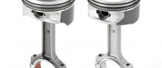
The gas distribution mechanism (GDM) is a set of parts and assemblies that ensure the opening and closing of the engine intake and exhaust valves at a certain point in time. The main task of the timing belt is to timely supply the air-fuel mixture or fuel (this depends on the type of engine) into the combustion chamber and exhaust gases. To accomplish this task, a whole complex of mechanisms works harmoniously, some of which are controlled electronically.
- Gas distribution mechanism
- Principle of operation
- Classification or types of timing belts
- According to the location of the camshaft
- By number of camshafts
- By number of valves
- By drive type
Principle of operation
The operation of the gas distribution mechanism is difficult to consider separately, in isolation from the engine operating cycle. After all, its main task is to open and close the valves in time for a certain period of time. Accordingly, on the intake stroke, the intake valves open, and on the exhaust stroke, the exhaust valves open. That is, in fact, the mechanism must implement the calculated valve timing.
Technically it happens like this:
It is also worth noting that during a full operating cycle, the camshaft makes 2 revolutions, alternately opening the valves in each cylinder, depending on the order of their operation. That is, for example, with a 1-3-4-2 operating scheme, at the same moment in time, the intake valves will be open in the first cylinder, and the exhaust valves in the fourth. In the second and third the valves will be closed.
Timing operation
This stage is divided, in turn, into two substages:
- cylinder operation;
- periods of gas distribution.
Cylinder operation
The alternating movements of the cylinders is their main job. Conditions depend on the location of the upper parts of the crankshaft and camshaft and the location of the cylinders themselves.
If there are four cylinders and they are lined up in a row, then the alternations occur in 180 degrees - 1-2-4-3 like the Volga, 1-3-4-2 - the VAZ Six or Moskvich.
In V-shaped engines with 8 cylinders, the journals are at right angles. The same angle between the cylinders. If the piston of any cylinder is at dead center, the neighboring one is in the middle. From here the left and right edges move a quarter of the crankshaft.
Gas distribution periods
This refers to the stages of opening and closing valves at the beginning and at the end. This is expressed in degrees of crankshaft angle. The cylinders must be kept as clean as possible, so exhaust gases must be released when the piston is at BDC. And at the TDC point the valve closes. The moment when two valves are open at once is called overlap.
All these phases are set by employees of the plant where the engine is manufactured, and depend on its power and speed. An oscillatory air movement is established in the opening and closing valves so that pressure is created at the moment of closing the opening valve and a vacuum at the moment of closing. Thanks to this, the fuel mixture arrives cleaner and exhaust gases are removed better.
When the mechanism is installed correctly, the distribution gears should engage the corresponding teeth. Misalignment by a few teeth can cause the piston to hit the cylinder itself too hard, causing valve failure, loss of pressure, or failure of the entire motor.
Another type worth noting is desmodromic gas distribution. There are 2 camshafts without springs: the first moves the valves down, the second up. The crankshaft in this form can gain a huge number of revolutions without fear of breakage or failure. Whereas a standard engine can break down at nine thousand. Desmodromic engines are very difficult to manufacture and expensive, and were used in the past mainly for racing cars. The first company to use this in their cars was Mercedes. Currently, the application is common in motorcycles.
Classification or types of timing belts
Engines may have different gas distribution mechanism layouts. Consider the following classification.
According to the location of the camshaft
There are two types of camshaft position:
With a lower position, the camshaft is located in the cylinder block next to the crankshaft. The force from the cams is transmitted through pushers to the rocker arms, using special rods. They are long rods and connect the pushrods at the bottom to the rocker arms at the top. The lower location is not considered the most successful, but it also has its advantages. In particular, a more reliable connection between the camshaft and the crankshaft. This type of arrangement is not used on modern engines.
In the upper position, the camshaft is located in the cylinder head (cylinder head) directly above the valves. In this position, various options for influencing the valves can be implemented: through pushers, rocker arms or levers. This design is simpler, more reliable and compact. The overhead camshaft position has become more widespread.
By number of camshafts
In-line engines may have one or two camshafts. Engines with one camshaft are abbreviated SOHC (Single Overhead Camshaft), and those with two camshafts are abbreviated DOHC (Double Overhead Camshaft). One shaft is responsible for opening the intake valves, and the other for opening the exhaust valves. V-engines use four camshafts, two for each cylinder bank.
By number of valves
The shape of the camshaft and the number of cams on it will depend on the number of valves per cylinder. There may be two, three, four or five valves.
The simplest option is with two valves: one works for inlet, the other for outlet. In a three-valve engine, two operate for intake and one for exhaust. With four valves: two for intake and two for exhaust. Five valves: three for intake and two for exhaust. The more valves at the intake, the greater the volume of the air-fuel mixture entering the combustion chamber. Increases engine power and dynamics. The size of the combustion chamber and the shape of the camshaft will not allow making more than five. The most common design is with four valves per cylinder.
By drive type
There are three types of camshaft drive:
The chain resource is enough for an average of 150-200 thousand kilometers.
The main problem with a chain drive is considered to be the breakdown of tensioners, dampers or rupture of the chain itself. If the tension is poor, the chain can jump between the teeth during operation, which leads to a violation of the valve timing.
Hydraulic tensioners help automatically regulate chain tension . They are pistons that press on the so-called shoe. The shoe is directly adjacent to the chain. It is a curved part with a special coating. Inside the hydraulic tensioner there is a plunger, a spring and a working cavity for oil. Oil enters the tensioner and pushes the cylinder to the desired level. The valve closes the oil channel, and the piston constantly maintains the desired chain tension. Hydraulic compensators in the timing belt operate on a similar principle. The chain damper dampens residual vibrations that the shoe did not dampen. This ensures optimal and precise operation of the chain drive.
The biggest trouble can come from breaking the chain.
The belt resource is also limited and on average it is 60-80 thousand kilometers.
Toothed belts are used for better grip and reliability. This drive is simpler. A belt breaking while the engine is running will have the same consequences as a chain breaking. The main advantages of a belt drive are ease of operation and replacement, low cost and silent operation.
The operation of the engine, its dynamics and power depend on the correct operation of the entire gas distribution mechanism. The greater the number and volume of cylinders, the more complex the timing device will be. It is important for every driver to understand the structure of the mechanism in order to notice a malfunction in time.
Source
SOHC...DOHC and other engine timing systems
A little theory...
Gas distribution mechanism
(
abbreviated name: timing
): a mechanism for controlling gas flows, namely supplying the fuel-air mixture to the engine cylinder and exhaust gases. The task of gas distribution is the timely, most efficient filling of the working volume of the cylinder and the complete, rapid release of exhaust gases, according to the stroke. The efficiency, power and developed torque of the engine depend on how accurately the timing and duration of the valve timing phases are calculated. The gas distribution mechanism can be organized using a valve mechanism with one or more camshafts, or perhaps using rotating sleeves or a spool mechanism. It is also worth noting gas distribution systems that completely exclude a camshaft of any design; in this case, the valves can be controlled using electrically controlled solenoids or by hydraulics or pneumatics.
The camshaft, where it exists, can be located either in the cylinder block itself (such an engine is called a lower valve
), and in the cylinder head (such an engine is called
overhead valve
)
SOHC, DOHC and everything connected with it...
What is SOHC:
The English-language names Overhead Camshaft and Single OverHead Camshaft (essentially the same thing) can be translated as “Overhead camshaft” and “single overhead camshaft”. The SOHC engine has a single camshaft mounted in the cylinder head, and the valves are operated either by rocker arms or directly via lifters.
What is DOHC:
The English names “Double Over Head Camshaft” and “dual overhead camshaft” can be translated as “Double overhead camshaft”. Thus, when they talk about a DOHC engine, they mean that this engine has two camshafts located in the cylinder head. A typical DOHC engine has two camshafts and 4 valves per cylinder. One camshaft controls the intake valves, which are mounted on one side, and the other camshaft controls the exhaust valves on the opposite side.
Differences:
After we figured out which engines are called SOHC and which DOHC. The difference between them becomes obvious and lies in the fact that the SOHC engine uses one crankshaft in the cylinder head, and the DOHC engine uses two. It is worth especially noting the point that these concepts do not in any way carry data on the number of valves per cylinder; there can be two, three or four (rare engines with 5 or 6 valves per cylinder are capable of working with either one camshaft with complex cam shapes or with multiple camshafts), both engine designs involve varying the number of valves.
SOHC engines are cheaper and less complex to design, build and maintain due to fewer moving parts, while DOHC engines are more complex to design, build and repair due to the additional moving parts. if you compare their performance, you will find that SOHC engines produce slightly less power than its DOHC sibling. DOHC engines are more flexible in valve timing, therefore delivering more of their power and are generally more economical. DOHC performance is more complex and higher, and at low and medium speeds such engines develop much more power for a similar SOHC, which makes them more preferable for racing or tuning cars.
The camshaft inside the cylinder block...
Pushrod engines, like SOHC and DOHC engines, have valves located in the head above the cylinder. The main difference is that the camshaft on a pushrod engine (OHV or Pushrod) is located inside the cylinder block rather than in the head. The whole purpose of subsequent upgrades and creation of DOHC and SOHC configurations is to get rid of the lifters and inertia of the OHV engine. OHV configurations use a centrally mounted camshaft (located in the center of the cylinder block) and the valves are actuated by lifters, pushrods and rocker arms. The OHC configuration eliminates much of this to reduce mass in the valve. This reduction in weight usually means that the engine can run safer and cleaner at higher engine speeds due to less inertial pressure on the valve actuator.
The cam operates long rods that extend through the block and into the head to move the rocker arms and valves. These long rods add mass to the system, which increases the load on the valve springs. This may limit the speed of the pusher motors. It was overhead camshaft technology that made higher engine speeds possible. The camshaft in a pushrod engine is often driven by gears or a short chain.
Engines without a camshaft:
Piston controlled valve timing:
The gas distribution mechanism with piston controlled intake and exhaust is used on two-stroke engines. The valve timing is set by the movement of the piston, opening and closing the intake and exhaust ports in the cylinder wall.
Spool-controlled valve timing:
To control the intake, a spool (valve) of a disk, petal or diaphragm type is used. Thanks to it, it is possible to make the intake phase asymmetrical relative to the top dead center of the piston and increase its duration to 180-200°, thereby improving the filling of the cylinder.
Sleeve-controlled gas distribution:
In this design, the cylinder liner is made in the form of a part moving along the cylinder axis, driven by the camshaft through a pair of helical gears. This drive ensures that the liner moves up and down, synchronized with the movement of the piston. At the same time, at a certain moment, the windows in the walls of the liner are opposite the response windows in the cylinder wall, then through them the working mixture is admitted and the exhaust gases are discharged.
Conclusions:
The history of engine development has seen many technological solutions for efficient gas distribution, some of them were complex, some were efficient and cumbersome, but as the years have shown, the most appropriate was a system that included two overhead camshafts. This design not only outperformed all the proposed options in terms of accuracy and precision of valve timing, but also became the basis for deeper engine upgrades (systems for changing valve timing and systems for changing the piston lift height). All these improvements have made modern engines more complex, but also much more efficient, powerful and resourceful.
Advantages and disadvantages of SOHC and DOHC:
The single overhead cam head weighs less which results in a lighter engine and vehicle overall, the SOHC is also a less complex mechanism than the DOHC and requires less force and fewer moving parts to turn a single camshaft. A Sohc valve will work well with a simple engine, but it will most likely need canes to add to the list of moving parts. Installing a dual overhead camshaft provides several advantages since dohc engines are widely used and their greater number of moving parts does not seem to bother engineers. One of the main advantages of dohc is that it easily includes four valves for each cylinder, two intake and two exhaust. Four valves per cylinder provide easier flow of fuel and gases both inside and outside the cylinder for the four-stroke cycle, thereby improving performance, especially at high speeds. Another advantage would be the position of the spark plug or diesel injector in a dohc engine, which would be in the center of the cylinder, allowing for more efficient combustion of the air/fuel mixture. It is also worth noting that the sohc type design also does not exclude 4 valves per cylinder. The DOHC design easily includes variable valve timing and valve lift, but this is not impossible on SHC engines.
So if you are still wondering about sohc vs dohc, they have their advantages.
A couple of interesting pictures on the topic:
| SOHC engines | ||
|
4 valves per cylinder |
2 valves per cylinder |
| DOHC engines | ||
|
|
|
| OHV engines | ||
|
| OHV cylinder head |
Purpose and characteristics
The gas distribution mechanism is the mechanism that opens and closes the intake and exhaust valves of the engine.
Figure 1 – Types of gas distribution mechanisms, classified according to various criteria
With an overhead camshaft, the camshaft is installed in the cylinder head where the valves are located. The valves are opened and closed directly from the camshaft through pushrods or valve actuator levers. The camshaft is driven from the crankshaft using a roller chain or toothed belt.
The upper location of the camshaft simplifies the engine design, reduces the mass and inertial forces of the reciprocating moving parts of the mechanism and ensures high reliability and quiet operation at high engine speeds.
The camshaft chain and belt drives also ensure quiet operation of the gas distribution mechanism.
With a lower position, the camshaft is installed in the cylinder block next to the crankshaft. The valves are opened and closed from the camshaft through rod pushers and rocker arms. The camshaft is driven by gears from the crankshaft. With a lower camshaft, the design of the gas distribution mechanism and engine becomes more complicated. At the same time, the inertial forces of the reciprocating moving parts of the gas distribution mechanism increase. The number of camshafts in the gas distribution mechanism and the number of valves per cylinder depend on the type of engine. Thus, with a larger number of intake and exhaust valves, better filling of the cylinders with a combustible mixture and their cleaning from exhaust gases is ensured. As a result, the engine can develop greater power and torque. With an odd number of valves per cylinder, there are one more intake valves than exhaust valves.
Camshaft device
The camshaft performs an important function in the operation of a car engine - it synchronizes the intake and exhaust strokes of the engine.
Depending on the type of engine, the timing belt can be with a lower valve arrangement (in the cylinder block) or with an upper valve arrangement (in the cylinder head).
In modern engine building, preference is given to the upper location of the timing belt. This allows you to simplify the process of servicing, adjusting and repairing the camshaft, thanks to ease of access to timing parts.
Structurally, the camshaft is connected to the engine crankshaft. This connection is made by means of a belt or chain. The camshaft belt or chain is placed on the camshaft pulley and crankshaft sprocket. The camshaft is driven by the crankshaft.
The most effective is the camshaft pulley - a split gear, which is used for tuning the camshaft in order to increase the power characteristics of the engine.
The cylinder head contains bearings in which the camshaft journals rotate. In case of repair, camshaft repair liners are used to secure the bearing journals.
Camshaft axial play is prevented by camshaft clamps. A through hole is made along the camshaft axis. Through it, the rubbing surfaces of parts are lubricated. On the rear side, this hole is closed by a camshaft plug.
The camshaft lobes are the most important component. Their number corresponds to the number of intake and exhaust valves of the engine. It is the cams that perform the main purpose of the camshaft - adjusting the engine valve timing and the order of operation of the cylinders.
Each valve has its own individual cam, which opens it, “running” onto the pusher. When the cam leaves the tappet, the valve closes under the action of a powerful return spring.
The camshaft cams are located between the bearing journals. Two cams: intake and exhaust for each cylinder. In addition, a gear is attached to the shaft to drive the distributor-distributor and the oil pump. Plus an eccentric to drive the fuel pump.
The gas distribution phase of the camshaft is selected experimentally and depends on the design of the intake and exhaust valves and the engine speed. Manufacturers indicate camshaft timing for each engine model in the form of diagrams or tables.
The camshaft cover is installed on the camshaft supports. The front camshaft cover is common. It contains thrust flanges that fit into the grooves in the camshaft journals.
Design and operation of the gas distribution mechanism
Gas distribution mechanisms, regardless of the location of the camshafts in the engine, include a valve group , transmission parts and camshafts with a drive .
The valve group includes intake and exhaust valves, valve guides and valve springs with mounting parts.
The transmission parts are pushrods, pushrod guides, pushrods, rocker arms, rocker arm axle, valve levers, shims and adjuster bolts. However, with an overhead camshaft, pushrods, guide bushings and pushrods, rocker arms and a rocker shaft are usually missing.
Timing faults
External signs of malfunction include:
- tapping in opening and closing valves;
- decreased blood pressure;
- reduction in engine power.
Such breakdowns of the gas distribution mechanism appear from insufficient contact of the valves with the seats. This occurs due to carbon deposits that are deposited on the walls over time, which leads to failure of the springs, the formation of cracks and the disappearance of the gap between the rod and the valve lever.
Grinding of the teeth of the crankshaft and camshaft gears, wear of the valve bushings and too much shift from its center of the camshaft are also considered timing faults.
Gas distribution mechanism with lower camshaft
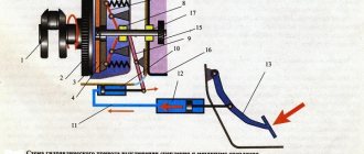
Figure 5 shows the gas distribution mechanism of an engine with a lower camshaft. The gas distribution mechanism is overhead valve, with a gear drive and two valves per cylinder.
Figure 5 – Gas distribution mechanism with a lower camshaft
1 – camshaft; 2 – valve; 3, 20 – bushings; 4 – spring; 5 – rocker arm; 6 – axis; 7 – screw; 8 – rod; 9 – pusher; 10, 11, 12 – gears; 13 – neck; 14 – eccentric; 15 – cam; 16 – cracker; 17, 19 – washers; 18 – cap
The mechanism includes a camshaft 1, a camshaft drive, pushers 9, pushrods 8, adjusting screws 7, rocker arm axle 6, rocker arms 5, valves 2, valve guides 3 and springs 4 with fastening parts.
The camshaft is steel, forged, has five bearing journals 13, cams 15 (intake and exhaust), gear 12 for driving the oil pump and ignition distributors, as well as an eccentric 14 for driving the fuel pump. The shaft is installed in the engine cylinder block on pressed-in bimetallic bushings made of steel and coated on the inside with a layer of lead babbitt.
The camshaft is driven through a driven gear 10, made of textolite, attached to its front end. It is meshed with a steel drive gear 11 mounted on the crankshaft. Both gears are helical to reduce noise and ensure smooth operation. The gear ratio of the gear drive - the ratio of the number of teeth of the drive gear to the number of teeth of the driven gear - is equal to 1:2, i.e. driven gear 10 has twice as many teeth as drive gear 11. This is necessary so that in two revolutions of the crankshaft the camshaft makes one revolution, ensuring that the intake and exhaust valves of each cylinder open once over a full engine cycle.
Pushers 9 serve to transmit force from the camshaft cams to the rods 8. They are made of steel, and their ends in contact with the cams are spherical and coated with bleached cast iron to reduce wear. Inside, the pushers have spherical recesses for installing rods. The pushers move in the guide holes of the cylinder block.
The rods 8 transmit force from the pushers to the rocker arms 5. They are made of aluminum alloy, and steel tips are pressed onto their ends.
Rocker arms 5 are designed to transmit force from the rods to the valves. The rocker arms are steel, have unequal arms to reduce the lifting height of the pushers and rods, and screws 7 are screwed into their short arms to regulate the thermal gap. The rocker arms are mounted on bushings on a hollow axis 6, fixed in the cylinder head.
Valves 2 are made of alloyed heat-resistant steel. To better fill the engine cylinders with the combustible mixture, the diameter of the head of the intake valve is larger than that of the exhaust valve.
Springs 4 are made of spring steel. The parts for their fastening are washers 17 and 19, cotters 16 and bushings 20. Rubber oil deflector caps 18 installed on the intake valves prevent oil from penetrating through the gaps between the guide bushings and the intake valve stems.
Mechanism operation
Source
What is a camshaft?
This shaft is needed so that at a certain moment the valves are opened, after which the working mixture enters the cylinder and exhaust gases exit. This is done thanks to the eccentrics that are on the shaft. It is rigidly connected to the crankshaft, so, for example, the intake valve opens only before the start of the intake stroke, when the cylinder is at bottom dead center.
The camshaft may be located in the head of the block, such engines are called overhead shafts, no matter how many shafts are installed here. It can also be in the cylinder block, as mentioned above. This is called a downstream motor. In this case, the drive to the valve is transmitted through rods that pass through the entire engine into the block head. The main disadvantage of this mechanism is its slowness and great inertia. Bottom-jet engines spin quite hard and have high oil consumption, unlike overhead-jet engines, where there are practically no drawbacks.
Types of timing belts
It is immediately necessary to clarify that above we considered the types of drive of the gas distribution mechanism, and not the mechanisms themselves. So, now let’s look, for example, at the difference between DOHC and SOHC. So, let's begin.
DOHC gas distribution system
This mechanism looks almost the same as the one discussed above, however, it differs from it in the presence of a second camshaft. Thus, one shaft drives only the intake valves, and the second drives only the exhaust valves. Such a system also has its disadvantages and advantages; we will not dwell on them in more detail. This system was invented in the 80s of the last century and has remained virtually unchanged during this time. So, the presence of a second camshaft significantly increases the cost and also complicates the design.
The video shows how the DOHC timing belt works:
On the other hand, DOHC timing mechanism has lower fuel consumption because the cylinders are better filled and then almost all the crankcase gases are released from them. Thus, the efficiency of the power unit reached a new level with the advent of DOHC.
What is a gas distribution mechanism (GRM)?
The gas distribution mechanism (GRM) is a mechanism designed to inject fresh charge into the engine cylinders (fuel mixture in classic gasoline engines or air in diesel engines) and release exhaust gases in accordance with the operating cycle, as well as to ensure reliable isolation of the combustion chamber from the environment during time of compression strokes and power stroke.
Depending on the type of devices that inject charge and exhaust exhaust gases, there are two types of gas distribution mechanisms:
The valve train is the most widely used and is used in all four-stroke engines. Upper and lower valve locations are possible. The upper location is currently used more often, since in this case the gas exchange process is more efficient. Typical designs of gas distribution mechanisms with overhead valves are shown in the figure.