Operating oil pressure in the KAMAZ engine
Content
ENGINE LUBRICATION SYSTEM FOR KAMAZ VEHICLES
The engine lubrication system is combined, with a “wet” sump. Pressurized oil is supplied to the crankshaft main and connecting rod bearings, camshaft bearings, rocker arm bushings, high-pressure fuel pump and compressor bearings. A pulsating oil supply is provided to the upper spherical supports of the pusher rods.
The lubrication system includes an oil pump, oil crankcase, filters - full-flow and centrifugal, air-oil radiator, oil channels in the block and cylinder heads, front cover and flywheel housing, external oil lines, oil filler neck, valves to ensure normal operation of systems and control devices.
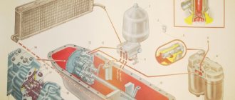
Rice. 30. Diagram of the lubrication system: 1 - compressor; 2 — high pressure fuel pump; 3 — fluid coupling switch; 4 - fluid coupling; 5, 12 — safety valves; 6 — lubrication system valve; 7 — oil pump; 8 — bypass valve of the centrifugal filter; 9 — centrifugal filter drain valve; 10 — oil radiator valve; 11 — centrifugal filter; 13 — warning lamp that the oil filter is clogged; 14 - oil purification filter bypass valve; 15 — oil purification filter; 16 — oil receiver; 17 — crankcase; 18 - main highway; A - to the radiator
The lubrication system diagram is shown in Fig. 30. From the crankcase 17 through the oil receiver 16, oil enters the discharge and radiator sections of the oil pump 7; from the injection section through a channel in the right wall of the block it is supplied to the oil purification filter 15, where it is cleaned by two filter elements, then enters the main line 18, from where it is directed through the channels in the block and cylinder heads to the crankshaft main bearings, rocker arm bushings and upper tips push rods. Oil is supplied to the connecting rod bearings of the crankshaft through holes inside the shaft from the nearest main journal. The oil removed from the cylinder walls by the oil scraper ring is discharged into the piston and lubricates the piston pin supports in the bosses and the connecting rod upper head bearing. Through the channels in the rear wall of the cylinder block and the flywheel housing, oil under pressure flows to the bearings of compressor 1, through the channels in the front wall of the block to the bearings of the high-pressure fuel pump 2. Provision is made for oil to be taken from the main line for supply to switch 3 of fluid coupling 4, which is installed on the front end of the unit and controls the operation of the fluid coupling of the fan drive. From the radiator section of the oil pump, oil flows to centrifugal filter 11, then into the radiator and then drains into the crankcase. When tap 10 is closed, oil from the centrifugal filter is drained into the crankcase through drain valve 9, bypassing the radiator.
The remaining engine parts and assemblies are lubricated by splash and oil mist.
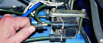
The oil pump (Fig. 31) is fixed to the lower plane of the cylinder block. The pressure section of the pump supplies oil to the main line of the engine, the radiator section supplies oil to the centrifugal filter and radiator. In the housings of sections 1 and 5, safety valves 11 and 18 are installed, adjusted to an opening pressure of 833.6. 931.7 kPa (8.5. 9.5 kgf/cm2) and designed to limit the maximum pressure at the outlet of the pump sections. Valve 14 of the lubrication system, triggered at a pressure of 392.4. 441.31 kPa (4.0. 4.5 kgf/cm2), designed to limit the pressure in the main line of the engine.
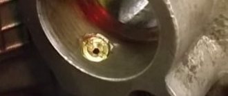
The oil purification filter (Fig. 32), installed on the right side of the cylinder block, consists of a housing 19, caps 24 and two paper filter elements 23. A bypass valve 16 with a filter element clogging indicator is installed in the filter housing. The warning light for filter element clogging is located on the instrument panel in the cockpit. The lamp is allowed to glow or blink when starting and warming up the engine. If the lamp is constantly lit on a warm engine, replace the filter elements.
Pressure sensors are installed in the filter housing
oil and alarm about an unacceptable decrease [less than 68.7 kPa (0.7 kgf/cm2)] of oil pressure in the main line.
The bypass valve allows crude oil to pass into the main line, bypassing the filter element, at low oil temperatures or significant clogging of the filter elements when the pressure drop across the elements is 245.8. 294.2 kPa (2.5. 3.0 kgf/cm2).
Centrifugal oil filter (Fig. 33) - with an active-reaction rotor drive, installed on the front cover of the cylinder block on the right side of the engine. Rotor 3 (Fig. 34) assembled with cap 2 is driven into rotation by a stream of oil flowing from the tangential slot in the rotor axis 11, as well as by reactive forces arising when the oil enters the tangential channels of the rotor.
When the engine is running, oil from the radiator section of the pump is supplied under pressure to the filter, ensuring rotation of the rotor. Under the action of centrifugal forces, mechanical particles are thrown towards the walls of the rotor cap and are retained, and the purified oil enters the air-oil radiator through the hole in the rotor axis and tube 17 or through the drain valve in the filter housing, adjusted to a pressure of 49.0. 68.7 kPa (0.5. 0.7 kgf/cm2), into the engine crankcase. The bypass valve installed in the filter housing is adjusted to a pressure of 588.4...637.5 kPa (6.0...6.5 kgf/cm2).
In order not to disturb the balancing of the rotor when servicing the filter, there are marks on the rotor and the cap that must be aligned when assembling it.
The stamped steel oil crankcase is bolted to the bottom plane of the cylinder block. A rubber-cork gasket is installed between the crankcase and the block to ensure a tight connection. There is a drain plug at the bottom of the crankcase.
Air-oil radiator, tubular-plate, double-row, air-cooled, installed in front of the radiator of the engine cooling system.
Technical characteristics of KamAZ engines
| Engine model | Crankshaft rotation speed, min-1: | ||||||
| — nominal | at idle speed, no more: | ||||||
| —— minimum | 600+50 | 2530-80 | 2930-80 | ||||
| Injection pump model | 337-20.04 “YAZDA” | PE8P120A920/5RV “BOSCH” | 337-20.04 “YAZDA” | PE8P120A920/5RV “BOSCH” | 273-20 “YAZDA” or 273-50 with “BOSCH” sprayer mod. DLLA 148 SV3 142503 | 273-21 “YAZDA” | 273-51 with sprayer “BOSCH” mod. DLLA 148 SV3 142323 |
| Nozzle injection start pressure, MPa (kgf/cm2): | TKP-7С-6 | S2B/7624TAE/0.76D9 “Schwitzer” | TKP-7С-6 | S2B/7624TAE/0.76D9 “Schwitzer” | TKP-7С-9 | S2B/7624TAE/1.00D9 “Schwitzer” | |
| Range of air supply through the compressor, kg/sec | 0.05 – 0.26 | 130 (1.3) | 100 (1.0) | ||||
| Rotor speed at rated engine power, min-1 | 100000 | Temperature of gases at the turbine inlet, °C: | |||||
| - allowed for 1 hour | 750 | ||||||
| - allowed without time limit | 700 | ||||||
| Oil pressure at the inlet to the turbocharger at an oil temperature of 80...950C, kPa (kgf/cm2): | |||||||
| — at a crankshaft speed of 2200 min-1 | 98 (1.0) | ||||||
During a service station, it is necessary to remove the turbocharger from the engine to clean the internal surfaces of deposits and wash them in diesel fuel. In this case, it is necessary to check the integrity of the blades and the absence of bends. The blades should be cleaned with a hair brush.
How does oil circulate in the oil system of the KamAZ-740 engine?
Oil from the sump flows through an oil receiver with a strainer into the oil pump sections. From the discharge section, oil is supplied through a channel to a full-flow filter, and from there to the main oil line. Then, through channels in the block and cylinder heads, oil under pressure is supplied to the crankshaft and timing parts, fuel injection pump and compressor. Oil is supplied to the connecting rod bearings through the crankshaft channel from the main journal closest to them. The supports of the rods and pushers of the gas distribution mechanism are washed by a pulsating jet, and the remaining parts are washed by splashing or gravity flow of oil. Oil removed from the cylinder walls by oil scraper rings is discharged through drillings in the piston grooves into the piston and lubricates the piston pin supports in the upper connecting rod head and piston bosses. From the main lubrication line, oil under pressure is supplied to the thermal power sensor, and when the fluid coupling valve is open, it is supplied to the fluid coupling itself. From the radiator section of the oil pump, oil is supplied to the centrifugal (fine) filter and through the open oil cooler valve to the radiator itself, and from it to the engine sump. If the oil cooler switch valve is closed, then oil flows from the centrifuge (centrifugal filter) into the sump through the drain valve. Insufficient oil supply to the rubbing parts of the engine causes loss of power, increased wear of parts, overheating and melting of the sliding bearings, jamming of the pistons and, ultimately, cessation of engine operation.
Increased oil pressure in the KAMAZ engine
Engine malfunctionsThe engine does not start
Reason: 1) Lack of fuel in the tank. 2) Presence of air in the fuel supply system. 3) Violation of adjustment of the fuel injection advance angle. 4) Freezing of water that has entered the fuel pipes or onto the fuel tank intake screen.
Remedy: 1) Fill the fuel tank, bleed the fuel supply system. 2) Eliminate leaks and bleed the system. 3) Adjust the angle. 4) Carefully warm up the fuel filters, pipes and tank with a rag moistened with hot water or steam; do not use an open flame for heating.
The engine does not develop the required power, it operates unsteadily, there is smoke when it is running
Reason: 1) Clogged air cleaner or air intake hood. 2) Insufficient fuel supply. 3) Violation of adjustment of the fuel injection advance angle. 4) Clogging of the nozzle (coking of the nozzle holes, stuck needle) or violation of its adjustment. 5) Improper adjustment of the governor control lever drive (the control lever does not reach the bolt for limiting the maximum crankshaft rotation speed). 6) Breakage of the injection pump pusher spring) 7) Dirt getting between the seat and the fuel pump valve or breakage of the spring. Violation of the tightness of the injection valves or spring breakage. 9) Jamming of the injection pump section plunger. 10) Improper adjustment of thermal clearances in the gas distribution mechanism. 11) Depressurization of the membrane cavity or damage to the charge air pressure corrector membrane. 12) The high pressure tube is loose or broken. 13) Poor compression due to malfunctions of the cylinder-piston group or loose fit of the gas distribution valves to the seats. 14) Thickening of fuel (during cold periods). 15) Low charge air pressure (Air leakage through the connections of the intake manifold with the cylinder heads, pipes, turbochargers and compressor. Gas breakthrough in the connections of the exhaust manifold and turbine housing. Seizing of the turbocharger rotor. Contamination of the exhaust tract, flow parts of the compressor and turbine).
Remedy: 1) Maintain the air cleaner or clean the hood mesh. 2) Replace the fine fuel filter elements, wash the coarse filter, tighten the connections in the fuel pipes. 3) Adjust the angle. 4) Rinse the nozzle, replace the nozzle if necessary, check and adjust if necessary. 5) check and adjust the regulator drive. 6) Replace the spring and adjust the pump on the stand. 7) Wash the valve or replace the spring, check the operation of the pump on the stand. Have valve leaks repaired in a workshop or replace the spring. 9) Replace the plunger pair and adjust the pump. 10) Adjust the gaps. 11) Restore the tightness of the membrane cavity or replace the damaged membrane. 12) Restore the oil supply to the corrector. 13) Tighten the fastening nut or replace the tube. 14) Check the condition of the pistons and piston rings, grind the valves. 15) Replace the fine fuel filter elements, replace the fuel with the appropriate fuel for the season, and bleed the fuel supply system. 15) Tighten connections; if necessary, replace gaskets and connecting hoses. Tighten connections; replace gaskets and connecting gaskets if necessary. Replace the turbocharger. Clean the pipelines, remove the turbocharger and remove deposits from the flow parts.
Extraneous noise in the turbocharger
Cause: The rotor is touching the housing parts.
Remedy: Tighten the bolts securing the turbine and compressor housings. Check that there is no interference with the rotor in its extreme positions. If the rotor is caught, replace the turbocharger. If the noise continues, remove the turbocharger for maintenance.
High frequency noise (whistle)
Cause: The tightness of the engine intake and exhaust tracts is broken.
Remedy: Tighten the bolts and nuts securing the system parts, replace the gaskets if necessary.
Increased oil consumption
Reason: 1) Prolonged operation of the engine at idle speed. 2) Oil leakage through connections in the turbocharger lubrication system. 3) Wear of the valve-bushing interface in the cylinder head, aging of the rubber valve seal. 4) Clogged air cleaner or air intake hood.
Remedy: 1) Do not operate the engine at idle speed unless necessary. 2) Tighten connections, replace gaskets and rubber sleeves if necessary. 3) Check and replace worn parts. 4) Maintain the air cleaner and clean the hood mesh.
Reduced oil pressure in the lubrication system
Reason: 1) Low oil level in the oil sump. 2) Malfunction of pressure control devices. 3) Use of oil of inappropriate viscosity. 4) Contamination of the oil filter filter elements. 5) Misadjustment or jamming of the safety valve or lubrication system valve. 6) Clogged oil pump intake. 7) Coolant getting into the oil. Oil leaks at joints and oil lines of the lubrication system. 9) Malfunction of the oil pump. 10) Unacceptable increase in clearance in the crankshaft and camshaft bearings.
Remedy: 1) Check and, if necessary, add oil to about. 2) Make sure that the devices are in good working order. 3) Replace the oil with the one corresponding to the chemical chart. 4) Replace filter elements. 5) Check the valves and eliminate jamming, if necessary, adjust or replace faulty parts. 6) Rinse the intake. 7) Check the tightness of the water cavity, the sealing of the cylinder liners, the tightness of the water-oil heat exchanger, replace faulty parts. Check the condition of process plugs, plugs, tightness of fasteners at joints, condition of O-rings and gaskets. 9) Remove the pump and check its functionality on a special stand. 10) Repair the engine.
Oil pressure in the KAMAZ 65115 engine (cold and warm)
Hello!
I have a KAMAZ 65115 2006
Please tell me what oil pressure is acceptable and should be on a hot engine and on a cold one?
On a cold engine, the pressure goes off scale to the limit, after a certain time the pressure in the engine becomes one. Tell me where to start and what to do?
Thank you in advance!
- Login or register to post comments
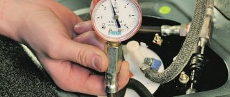
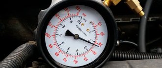
About oil pressure and measurement methods in the KAMAZ engine
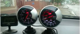
Engine pressure should be measured only on a warm engine, and preferably with a mechanical sensor. The indicators should be as follows:
At idle speed (600 rpm) - 0.1 MPa,
At 2200 rpm - 0.4 MPa
If the indicators are different, then you need to contact a specialist for a more in-depth analysis.
- Login or register to post comments
KAMAZ 740 engine Why do liners crack and the engine shakes?
Engine 740 euros 0.
The second time the liner cracked, and the engine shook, but if you increase the speed to 1500 it stops shaking
Source
What should the engine oil pressure be?
There is no uniform standard for engine oil pressure, and the reason is simple: the design of motor systems from different car manufacturers has some differences. But even here there is one general rule: the oil pressure at idle speed on the engine cannot be higher than in load mode. The fact is that the faster the system elements rotate, the more lubrication they require.
To understand what the indicator we are interested in should be, it is necessary to imagine the principle of its measurement. Modern cars are equipped with special sensors - they monitor the condition of the oil in the system. Unfortunately, they are not accurate in all cases, but a triggered sensor can both save money on repairs and save lives. And if repairs are still required, it will cost a lot.
The operating manual for the vehicle indicates the main technical characteristics and operating modes of the lubricant. You can also usually find brands of fluids that are best suited for a particular engine. By the way, manufacturers offer branded oil under the brand of automakers.
There are two normal states of engine oil pressure:
- at idle, that is, the engine idles at low speeds, so it only needs about 2 bar or 0.2 MPa;
- at high speeds, here the figure depends on the specific car, but for cars it is in the range of 4–7 bar.
You can find indicators that are considered normal in the repair and operation manual for your car.
So, for the famous Russian car “Lada Priora” at idle the norm is 196.2 kPa, that is, about 2 bar, and at 5,400 rpm the norm is 4.5–6.5 bar. This level is considered the maximum for the car.
Manufacturers of American brands usually write normal pressure per 1,000 rpm. At 1,000 rpm the average is 10 psi (or 67 kPa). For example, at 2,000 rpm the norm is 1.3 bar, and at 5,000 rpm the figure increases to 3.4 bar. But when assessing these indicators, we should not forget about the difference between domestic cars and foreign cars, as well as the differences in operating conditions.