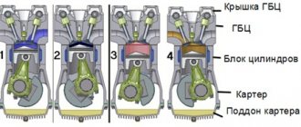
Spark plugs don't work
The task of glow plugs is to heat the fuel in the cylinders. They receive energy through a special relay. Heating is carried out under the control of a control unit, which after a certain time turns off the voltage supply to the glow plugs.
Determining their malfunction is not so easy: even if 1 or 2 parts work intermittently, the engine may start. You can check the spark plugs by measuring their resistance with an ohmmeter. If there are problems with them, at the moment of start the engine will “require” connection to the starter to start. If the relay or ECU is faulty, then after turning the key in the lock, there will be no characteristic soft click before starting.
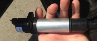
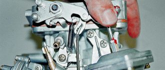
This is what glow plugs look like
Cleaning diesel engine injectors
Having assessed the presence of a problem, in some cases it is possible to restore functionality by cleaning or intermediate repairs. Contaminants can be removed using chemical and mechanical methods.
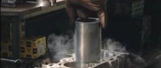
Ultrasound
The effect of high-frequency acoustic vibrations is quite effective; even inscriptions applied at the factory with special paints are often washed off from parts.
The removed nozzle is placed in a bath filled with cleaning liquid, to which a powerful ultrasound emitter is connected. The cleaning process lasts about 20 minutes, after which the results are monitored at the stand.
The most modern injectors, which contain many delicate plastic parts, can begin to work even worse than before cleaning, so they need to be checked in all respects, and not just by the type of torch.
Bench cleaning
A special flushing liquid, which is a very effective solvent, is poured under pressure through a contaminated injector.
This is the most reliable method of cleaning, since the part is not subjected to any destructive influences, and everything is focused on dissolving deposits and contaminants.
At the same time, using the same stand, the results of the work are monitored, after which it will be possible to make the most accurate decision on the possibility of further use of the sprayers.
Use of additives
There are a large number of various cleaning additives for diesel equipment on sale that work by simply adding them to the fuel.
The effectiveness of this method is quite doubtful, since high-quality diesel fuel already contains substances of this kind and, with constant use, does not allow the appearance of deposits. And it is difficult to wash off existing ones due to the low concentration of detergent components.
On the subject: How to properly tow a car with automatic transmission (variator) and manual transmission (mechanics)
In addition, you can get the opposite effect in the case of a heavily polluted system, when large fractions separate and enter bottlenecks, completely clogging them. However, obtaining a positive result is also not excluded.
Manual method
It can be done either by disassembling the nozzle or by pouring cleaning liquid through it. In the latter case, it is no different from washing on a stand except for complexity.
When disassembling the nozzle, where this is structurally permissible, you can clean and grind the valves, mechanically remove contaminants from accessible parts, and even clean the nozzle holes with soft wire.
The main thing is to exercise sufficient caution, taking into account the precision accuracy of all parts. For flushing, the same liquid for cleaning injectors is used.
Checking relays and ECUs and other sensors
- It may be necessary to remove the fuel pump to check. You will need to remove the rear seat and check the voltage at the pump terminals. The device should show + 12 volts. Then crank the engine using the starter. When it is triggered, they proceed to subsequent actions. It may happen that when you turn the ignition key, the starter does not turn. Then you need to check the reliability of all wires on it. The cause may be a problem in the contact group in the ignition switch.
- If it is determined that everything is in order, check the spark on the spark plugs. To do this you will need to open the hood. First, you need to unscrew the spark plug from the first cylinder. It is necessary to throw an armored wire over it and press it against the mass. In this case, the candle must be held with pliers and not with your hands. Otherwise you will get an electric shock. At this time, the assistant starts the engine. All other candles are checked in the same way. If there is a spark on each cylinder, it is necessary to look for ignition problems.
- The situations may be different, for example, a spark is present on cylinders 1 and 4, but not on cylinders 2 and 3. The ignition module should be replaced. If the replacement does not give a positive result, you should look for the reason in the output transistor switches to the ignition module from the ECU. The ECU may need to be repaired.
- It may happen that there is no spark on any cylinder. VAZ 2110 does not start because there is no spark. Often the reason for this lies in the crankshaft position sensor. The DPKV ECU gives a signal through which pulses are sent to the ignition module so that a spark is formed. The cause of the malfunction may be the lack of connection between the gear and the generator wheel. This can occur even if the DPKV is in full working order. At the same time, the crankshaft rotates, but the sensor will not process these rotations. Many are frightened by the fact that the VAZ 2110 injector has a large number of sensors. Indeed, there are a lot of them, but the reason that the VAZ 2110 does not start the first time is only one thing - the DPKV sensor is faulty.
- It is necessary to unscrew the spark plug from the cylinder and check its moisture content. A dry spark plug indicates that the injector is not spraying fuel. Then check the pressure in the fuel rail. It has a special bolt on the side. It must be unscrewed and a pressure gauge inserted in its place. It will show the presence or absence of pressure in the ramp. But it may not be at hand. Then the bolt is unscrewed and the pump starts. If there is pressure in the ramp, a good stream will flow out of the hole.
- If there is no pressure, the fuel filter must be replaced. The reason may also be that the line on the way from the fuel tank to the ramp is clogged. If the unscrewed candle turns out to be wet, then they all need to be unscrewed, wiped and dried thoroughly.
- Sometimes the reason is that the injectors are clogged and need to be cleaned. Clogged injectors may cause the spark plugs to be flooded with fuel. Dirty injectors are often the reason why a car engine has difficulty starting.
- Sometimes the reasons that the VAZ 2110 16 valves does not start may be of a deeper nature. They are very difficult to diagnose. But for the VAZ 2110 this is the exception rather than the rule.
VAZ 2110 injector 8 valves does not start when cold
For owners of a car of this brand, this problem, unfortunately, is not uncommon. It must be said that most of the blame does not belong to the manufacturer, but to the frosty weather conditions in which the car is located.
It will be useful: Replacing the heater radiator on a Lada Kalina without removing the panel: video instructions
If in winter a car sits outside all night or in a garage that is not heated, then all the problems arise because it has completely cooled down.
At the same time, the metal, fuel, and lubricant change their physical properties.
All this ultimately leads to the fact that it becomes quite difficult to start the power plant. Problems will be added by the fact that the car is not properly maintained regularly.
The most common reasons for this situation are the following:
- There is a specific problem with the battery.
- The gasoline pump has failed.
- The sensors that monitor the crankshaft and those that monitor the condition of the camshaft are faulty.
- The problem is the candles.
- The alarm goes off.
- The system that redistributes fuel is experiencing problems.
- An element in the ignition unit has failed.
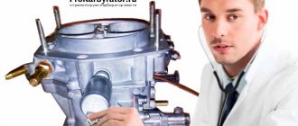
Checking and replacing the fuel pressure regulator
As you can see, a malfunctioning pressure regulator has symptoms very similar to a malfunctioning fuel pump or a clogged fuel filter. At the very beginning, we note that if problems with this element are detected during the inspection, then it is preferable to replace the RTD with a new one. The fact is that replacing individual parts, cleaning attempts and other manipulations often do not allow the device to return to proper functionality. Considering that the price of a fuel pressure regulator is quite affordable, then any repair attempts can be considered impractical.
Measurements should show changes in pressure in the system within a certain range. The fuel pressure should increase, being within the range of 0.3 - 0.7 Bar. If this does not happen, then first you can try replacing the vacuum hose, and then repeat the measurements. To check the fuel pressure at the end of the ramp, you will need to unscrew the fitting plug. This plug also has a special ring for sealing. The specified ring should be checked for integrity; the element should remain elastic. If there are defects, then the ring or the entire plug also needs to be changed at once.
- After inspecting the ring, you can unscrew the umbrella from the fitting. Many drivers use a metal wheel valve cap to loosen it. Now the hose and the pressure gauge connected to it need to be connected to the fitting, after which the structure is additionally secured using clamps. Next, the engine can be started and measurements taken. Normally, the indicators should be about 2.9-3.3 kgf per cm2. Afterwards, you can disconnect the hose from the RTD, observing the pressure gauge readings. The pressure indicator should increase from 20 to 70 kPa.
- If the fuel pressure regulator still produces a low or zero reading, then you can think about replacing the device. Changing an RTD is not a difficult task, that is, you can do the replacement yourself in a garage. At the beginning of the procedure, you need to “bleed off” the pressure in the engine power supply system. To solve the problem, you need to unscrew the nut that secures the fuel pipe. Now you can unscrew a couple of bolts that usually attach the regulator to the fuel rail on most fuel-injected cars.
- The next step is to carefully remove the regulator fitting from the hole in the fuel rail and its final dismantling (the fuel pipe must be completely disconnected in advance). The final stage is the installation of a new or known-good element into the ramp, after which the functionality is checked in the manner described above using a pressure gauge. Finally, we would like to add that it is also recommended to additionally lubricate the O-rings with gasoline before installing a new RTD or in case of replacing the said rings.
Diesel does not warm up to optimal temperature
When warming up a working diesel engine in idle mode, it is advisable to wait until the coolant heats up to a temperature of about 40-50°C. If there is a strong minus outside, the diesel engine may even begin to warm up only while driving. You need to start driving in a lower gear, sticking to around 2-2.5 thousand rpm. When the temperature rises to 80°C, the load on the motor can be increased.
If a diesel engine does not reach operating temperature while driving, this indicates that its efficiency has decreased. Power decreases, the car accelerates worse, diesel fuel consumption increases, etc. These symptoms may indicate the following problems:
- malfunction of the engine cooling system (thermostat);
- the compression ratio is not normal (low compression);
Operating a diesel engine that has not warmed up to operating temperature under serious load leads to incomplete combustion of the mixture, active formation of soot, clogging of fuel injectors, accelerated wear of power unit components, failure of the particulate filter, etc.
As an example, consider a clogged diesel injector nozzle. The quality of fuel atomization decreases, the nozzle “pours” diesel fuel. The fuel begins to burn unevenly and untimely, burns out on the piston and causes it to burn out. The exhaust valve may also burn out. The result is a drop in compression, that is, the air in the faulty cylinders will not be able to compress to a temperature at which combustion of the mixture will be optimal. In such conditions, a diesel internal combustion engine will not reach operating temperature and will have difficulty starting “cold” and after warming up.
- Why does a diesel engine get hot?
Causes and results of diesel engine overheating. What to do if the diesel engine is overheating: diagnostics and troubleshooting. Important recommendations. Read more
- Why does the engine temperature drop while driving?
The engine temperature does not rise, the internal combustion engine temperature needle drops while driving. Why does the temperature drop after turning on the stove? Diagnostics and repair, advice. Read more
- Why does the engine take a long time to warm up: the main reasons
The engine warms up slowly at idle or while driving: why does this happen? Possible malfunctions of the cooling system, other reasons. Read more
- To what temperature should the engine be warmed up?
How to properly warm up a car engine. Features of warming up engines with a carburetor, injector and installed gas equipment, as well as diesel engines. Read more
- Where is the engine temperature sensor located?
Engine temperature sensor (ETS): operating features, device, sensor installation location. Malfunctions related to the internal combustion engine temperature sensor, check. Read more
- The engine temperature gauge does not rise, it jumps...
The engine does not reach operating temperature, the engine temperature arrow does not rise during warm-up or falls while driving: causes of the malfunction. Read more
Methods for checking an injector
The more complex the diagnostic equipment used, the more accurately you can determine the causes of what happened and prescribe the necessary measures to eliminate the problem.
Power check
The simplest way to control the pulses arriving at the injector connector is to connect an LED indicator to its power contact.
When the starter rotates the shaft, the LED should blink, which indicates the approximate serviceability of the ECM keys and the very fact of its attempts to open the valves, although the incoming pulses may not have sufficient power.
Only an oscilloscope and a load simulator can provide accurate information.
How to measure resistance
The active nature of the load can be checked using an ohmmeter included in the universal multimeter (tester). The resistance of the solenoid winding is indicated in the nameplate data of the injector, as is its spread.
The ohmmeter reading should confirm the consistency of the data. Resistance is measured with the connector between the power contact and the housing disconnected.
But in addition to resistance, the winding must provide the required quality factor and the absence of short-circuited turns, which cannot be determined in the simplest ways, but a break or a complete short circuit can be calculated.
Ramp check
If you remove the ramp and injector assembly from the manifold, you can assess the condition of the nozzles more accurately. By immersing each injector in a transparent test tube and turning on the starter, you can visually observe the spraying of fuel.
The torches must have the correct conical shape, contain only individual droplets of gasoline indistinguishable to the eye, and most importantly, be identical across all connected injectors. In the absence of control pulses, there should be no release of gasoline from the valves.
Checking injectors on a bench
A specialized installation can provide the most accurate and complete information about the condition of the nozzles. The injectors are removed from the engine and installed on the stand.
The device has several operating modes, one of which is test. The installation cycles in various modes, collecting the released fuel and measuring its amount. In addition, the operation of the injectors is visible through the transparent walls of the cylinders, and the parameters of the torches can be assessed.
The result will be the appearance of performance figures separately for each device, which must correspond to the passport data.
Cleaning the diesel intake system
Files:
The diesel intake system includes an air filter, the cold part of the turbine, an intercooler, an intake manifold, an EGR valve and its cooler, and intake valves.
We will consider the impact on engine operation of the condition of the intake manifold and EGR valve, as systems that most strongly influence engine operation.
Increased resistance of the air intake system and crankcase ventilation (contamination of the EGR valve and manifold) on a diesel engine leads to the following problems:
the engine does not start in warm and cold weather the engine is difficult to start the engine starts but immediately stalls unstable idling lack of power excessive fuel consumption black exhaust blue or white exhaust excessive oil consumption overheating of the diesel engine increased pressure in the crankcase unstable operation of the diesel engine
The service life of various EGR systems ranges from 70 to 100 thousand kilometers (in domestic conditions about 50 thousand). After this, its components must be replaced. This is ideal. However, there are few people willing to pay a lot of money, so many car repair companies include in the list of routine maintenance measures to clean and, accordingly, extend the life of system components. In the EGR pneumatic valve, it is necessary to periodically clean the seat and rod from carbon deposits. In systems with a control solenoid valve, it usually has a filter that protects the vacuum system from contamination. It needs to be cleaned periodically.
When EGR starts to malfunction, many car owners prefer to turn it off. As a rule, this is done using a gasket cut from thin sheet metal and installed under the valve. However, as a result, the temperature in the combustion chamber increases, and this increases the risk of cracks in the cylinder head.
Typical contamination of the intake tract of Opel, Volkswagen and the intake manifold cleaning field:
EGR valve and intake manifold cleaning technology:
Warm up the engine to operating temperature. Stop the engine and provide access to the intake tract by removing, for example, the pipe supplying air from the turbine. Start the engine (Attention: injection of the drug is carried out only with the engine running!) and spray Pro-Line Ansaug-System-R einiger Diesel onto the dirt deep into the intake manifold at short intervals of 2-3 seconds. Maintain engine speed around 2000 rpm
If the speed increases spontaneously by more than 1000 rpm, stop spraying immediately! Use up the contents of the cylinder and control the cleaning visually. Turn off the engine and restore previously disassembled connections. If necessary, erase accumulated errors in the ECU (engine control unit).
It is recommended to include cleaning of the intake tract in routine maintenance of a vehicle, especially with a mileage of more than 100,000 km.
liquimoly.ru
HYDROMECHANICAL INJECTORS
Hydromechanical nozzles (HM nozzles) are of open and closed types. The first type of GM injectors are jet injectors and are not used in modern gasoline injection systems. GM injectors of a closed type are intended for use in mechanical systems of continuous fuel injection distributed among the cylinders on gasoline internal combustion engines. These injectors are not electrically controlled. They open under the pressure of gasoline and close with a return spring. The gasoline pressure at which a closed injector opens is called the initial operating pressure (IOP) of the injector and is designated as Rfn. Closed-type GM injectors are installed in the pre-valve areas of the intake manifold for each cylinder separately.
In design, closed injectors can differ in the design of the shut-off valve and the method of mounting in the cast housing of the intake manifold. Based on the type of shut-off device, closed nozzles are divided into nozzles with a spherical, disk and pin valve; according to the method of fastening - plug-in and threaded.
Closed GM injectors do not take part in fuel dosing. Their main function is to spray gasoline onto the hot engine intake valves. In this case, the atomized gasoline particles turn into a vapor state, and the intake valve cools. To avoid contact of the gasoline stream with the walls of the pre-valve zone of the intake manifold, gasoline is sprayed with an opening angle of no more than 35 degrees, and the nozzle is installed in relation to the valve according to a strictly specified geometry.
Fuel dosing in a mechanical injection system is carried out by changing the gasoline pressure at the constantly open spray nozzle of the injector. In this case, the pressure pressure is formed by pressure outside the nozzle - in the differential valve of the metering distributor of the mechanical injection system.
In order for the closed-type injector valve to be in the “open” state, the gasoline pressure in the valve cavity 6 must always be slightly higher than the force Pp of the return spring 10 (Pfn > P„).
This is achieved by setting a sufficiently high (at least 6 bar) operating pressure Ps (OPS) in the system (in the fuel supply line to the metering distributor) and maintaining the Ps Ps at a constant level.
THE MAIN PARAMETERS OF A CLOSED NOZZLE ARE FIVE INDICATORS.
1. Initial operating pressure Рфн (НРП) of the nozzle immediately after its assembly at the manufacturer (opening pressure of a new nozzle). NRP for closed nozzles of various modifications lies in the range of 2.7...5.2 kg/cm2. For new injectors from the same size range, the NSD may differ by no more than ±20%. When selecting a set of injectors for an engine, the difference in NWP should not exceed ±4%. The injectors are sold for sale (as spare parts) with the same NSD in the packaging. Replacing injectors with an incomplete set may cause problems with normal engine operation.
Useful: Design and principle of operation of the injection system
2. Minimum operating pressure Рфт|„ (MWP) of the injector after its running-in on the engine (after 5000 km). This pressure becomes less than the NWP of the new nozzle by 15...20% and stabilizes (over 5 years of normal operation it changes by no more than 5%).
3. Working pressure of the RF injector after its running-in. This is the pressure in the internal cavity of the injector that changes during engine operation from the minimum operating pressure Рф min (MWP) to the maximum operating pressure Ps max (РПС) in the mechanical injection system.
4. Injector cut-off pressure P0 (DOT). This pressure below which the nozzle is securely closed is sometimes called drain pressure). The cut-off pressure is always less than Рф min by 1.0...1.5 kg/cm2, but slightly higher than the residual pressure Increase in the injection system immediately after turning off the engine.
5. Performance of Pf injectors. This is the amount of gasoline that is sprayed through a constantly open nozzle per unit of time at a certain operating pressure Рф in the nozzle cavity. Typically, Pf of a closed nozzle is set for two extreme values of operating pressure: Pf min and Ps max. These two values correspond to two engine operating modes: Рф m,n - idling, Ps m8K - full load. The productivity of Pf is set in cm3/min or in g/s. For example, for closed injectors of a 5-cylinder internal combustion engine of an AUDI-1O0 car (2.2 l, 140 l/s), the performance indicators are respectively 30 and 90 cm3/min (when working in the K-Jetronic system).
Failure closed-type injectors cannot be repaired, but, like any others, they can be “washed” as part of the injection system while the engine is running.
ELECTROMAGNETIC INJECTORS
Electromagnetic injectors are used in modern gasoline injection systems as valve operating and starting injectors (for electronically controlled cylinder injection systems), as well as central injection nozzles (in power systems with single injection). The central nozzle is the most common design for gasoline injection systems of the “Mono” group.
Modern EM injectors are capable of reliably operating with a duty cycle* S = 0.5 and at the same time stably (controllably) maintaining the open state for 2...2.5 ms. The spread of this parameter in a specific size range of injectors is no more than ±5%. This speed of operation of the EM injector corresponds to the frequency of the reciprocating movement of the movable rod of the injector electromagnet of 200...250 s-1. This is the limit of what is possible for this type of electrically controlled injectors.
When using EM injectors as valve injectors, the operating pressure Ps in the injection system can be reduced from 6.5 bar (in mechanical systems) to 4.8...5 bar, which increases the reliability of the electric fuel pump and reduces the likelihood of fuel leaks in the gasket sealing joints. gistrals.
With electronic control of injectors, the accuracy of dosing of injected gasoline is significantly increased. This becomes possible because the pressure inside the EM injector is maintained constant, and the amount of injected fuel is determined only by the time the injector is open.
THE MAIN PARAMETERS OF THE EM NOZZLE ARE:
1. Constant operating pressure in the nozzle cavity (COP), equal to the operating pressure Ps of the system, expressed in bar.
2. Nozzle performance (throughput capacity in the OPEN CONDITION - IN CM3/MIN or in g/s at a given RDS Ps).
3. Minimum voltage for reliable operation of the injector (constant voltage in volts).
4. Minimum time of cyclic fuel supply (minimum reliably controlled time of duration of the injector open state - in ms).
5. Internal ohmic resistance Nf of the injector (resistance of the solenoid coil - in ohms).
A digital code is printed on the injector body, which can be used to determine all of the above parameters in the reference catalog. The trademark or name of the manufacturer is also stamped on the body.
The internal ohmic resistance Nf of the injector should be discussed separately. If the solenoid coil is wound with copper wire, then it is impossible to obtain a value of Нф more than 2...3 Ohms (the requirement to minimize the inductance Ls of the coil is imposed). In this case, to limit the operating current 1ph of the injector, an additional resistor is connected in series with the solenoid coil. A high resistivity winding wire is also used (for the solenoid coil), which eliminates the need to install additional resistors. But in any case, the total average control current of all injection nozzles (or a group of nozzles) on the engine at once should not exceed 3...5 A.
In some cases, “group” control of injectors is used on multi-cylinder engines. This is when the injectors are combined into groups, and each group is controlled from a separate electronic unit. But the most effective is the gasoline injection system, in which each working valve EM injector is controlled independently of the others (sequential synchronized pulse gasoline injection distributed among the cylinders controlled by a multi-channel injection computer).
Useful: All Gazelle engines
Based on the type of shut-off valve, EM nozzles, like hydromechanical ones, are divided into three types:
— nozzles with a spherical shut-off element profile:
- nozzles with a pin valve (with a cone or needle shut-off rod):
— nozzles with a disc valve (with a flat or poppet shut-off element).
Nozzles with internal electrical resistance of 2.4 Ohms are available: 12.5 Ohms; 16 Ohm. Low resistance is associated with the use of a copper winding wire and with the need to have a small value of inductance L of the solenoid, which directly depends on the number of turns Wc of the solenoid winding.
The low resistance of the injector is increased by an additional resistance of 6...8 Ohms, which reduces the consumed current. The windings of a high-resistance injector are made of wire with a high resistivity (for example, brass), which allows you to have a small L and a large R.
In terms of P injection performance, injectors are selected according to the types and power of the engines on which these injectors are installed. The performance of the injector is determined under the operating pressure of the system, as the amount of kW of gasoline passing through the injector per unit of time t, if it is constantly open.
STARTING ELECTROMAGNETIC INJECTORS
Electromagnetic injectors also include hydraulic starting valves with electromagnetic control, which in their operating principle are not much different from EM injectors. That is why hydraulic starting valves are often called starting injectors.
The main purpose of the starting injector (PS injector) is to work in a mechanical continuous distributed injection system during starting a cold engine. Sometimes a PS injector is used as an afterburner device, like an accelerator pump in a carburetor, or as a device for starting an overheated turbocharged engine. The starting injector is also used in some L group injection systems. In any case, the PS injector operates directly from the vehicle’s electrical system, and is connected indirectly to the electronic engine control system through a special electronic control relay.
There are no high response speed requirements for PS injectors, which greatly simplifies the design of its components. Thus, the mass of the electromagnet armature, which (the armature) is also the locking element of the injector valve, the number of turns of the electromagnet coil, the cross-section of the spray nozzle, the elasticity of the return spring - all this is noticeably increased compared to the working valve EM injector.
Starter and battery
Most starting problems occur due to wear of these two elements. After all, starting the engine “cold” and “hot” depends on them. If your diesel engine has difficulty starting when cold, the reason may be a discharged battery. The latter, like diesel fuel, is also afraid of low temperatures. It can lose up to 20 percent of its capacity overnight. This is already a critical indicator. As a result, even the new Renault Duster will be impossible to launch. What is the solution to the problem? There is only one way out here - charging the dead battery. There are several ways to do this. The fastest option is “lighting up”.
The second, safer way is to use so-called boosters. Recently they have become very popular among motorists. The booster is a small battery (comparable to the size of a Power Bank for mobile phones) that can produce a high inrush current for 30 seconds in the “Boost” mode (hence the name). This battery is 12-volt and is suitable for most cars and minibuses with an engine capacity of up to 4 liters. However, practice shows that a high-quality “booster” can even start a truck engine. The only drawback of such a battery is the price. It is comparable to the cost of three good lead batteries.
The third method is charging on a stationary charger. This is the safest, but slowest way. After all, to restore the charge lost by 20 percent, the device will need at least 30 minutes of time.
As for the starters, they also fail. It is possible that the terminal does not fit well to the device, or the drive gear that engages with the flywheel ring is worn out. In any case, you can determine the malfunction “by ear”. The starter will make different sounds when operating.
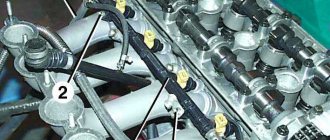
Removing the injectors
All manipulations with the injectors must be carried out in complete cleanliness; debris entering the combustion chamber can damage the engine, so before dismantling the power system, it is recommended to clean the engine with compressed air or simply wash the cylinder head
It is important to remove contamination before starting the dismantling process. If abrasive gets into the threads, it will have a detrimental effect on the service life of the car.
The nozzle must be disassembled on a clean table covered with a white sheet of paper.
To simplify subsequent assembly, it is necessary to mark all dismantled tubes and cables. Otherwise, installation may be performed incorrectly. If photo or video recording is possible, it is recommended to take advantage of this.
Dirt and ring residues adhering to the grease must be removed with a cotton swab. You can turn the crankshaft several times. Air flows will blow out all excess from the seat.
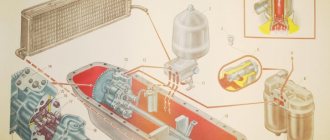
How does fuel dosing work? High pressure solenoid valve
The solenoid valve (valve for setting the injection start timing) consists of the following elements:
- valve seat;
- valve closing direction;
- valve needle;
- electromagnet armature;
- coil;
- electromagnet;
The specified solenoid valve is responsible for the cyclic supply and dosing of fuel. The specified high pressure valve is built into the high pressure circuit of the injection pump. At the very beginning of injection, voltage is applied to the electromagnet coil (5) according to a signal from the control unit. The anchor (4) moves the needle (3) by pressing the latter against the seat (1).
When the needle is pressed tightly against the seat, then no fuel flows. For this reason, the fuel pressure in the circuit increases rapidly. This allows the corresponding injector to be opened. When the required amount of fuel is in the combustion chamber of the engine, then the voltage on the electromagnet coil (5) disappears. The high pressure solenoid valve opens, which entails a decrease in pressure in the circuit. The decrease in pressure causes the fuel injector to close and injection to stop.
All the accuracy with which this process is carried out directly depends on the solenoid valve. If we try to explain in even more detail, then from the moment the valve ends. This moment is solely determined by the absence or presence of voltage on the solenoid valve coil.
Excess injected fuel, which continues to be injected until the plunger roller passes the top point of the cam profile, moves through a special channel. The end of the path for fuel is the space behind the accumulating membrane. In the low-pressure circuit, surges from high pressure occur, which are damped by the accumulating membrane. An additional feature is that this space stores (accumulates) the accumulated fuel for filling before the next injection.
The engine is stopped using a solenoid valve. The fact is that the valve completely blocks the injection of fuel under high pressure. This solution completely eliminates the need for an additional stop valve, which is used in distribution injection pumps where the control edge is controlled.
Why do you need a fuel pressure regulator?
As mentioned above, this regulator maintains the required fuel pressure necessary for normal operation of the injectors, taking into account one or another operating mode of the power unit. In other words, the RTD affects the amount and intensity of the fuel supply that enters the engine cylinders through the injectors.
Simply put, the amount of fuel supplied to the engine at the time of injection depends on the pressure that is created inside the fuel rail (rail), as well as on the pulse duration for opening the injector and the vacuum in the intake manifold.
For more accurate dosing and maintaining constant pressure, a diaphragm valve-regulator is used, which experiences fuel pressure on one side, and a spring force on the other. RTD is used in power systems where there is a so-called “return”. The regulator is installed at the fuel rail. Also, this element can be located in the fuel tank, while such systems do not have a return line.
- Let's first look at the common design in which the regulator is located in the fuel rail. The element operates on the following principle: the fuel pump forces fuel from the fuel tank along the line. The resulting fuel pressure acts on the regulator. The device itself has two chambers (a spring chamber and a fuel chamber), which are separated by a membrane. On one side, the membrane is pressed by fuel, which enters the regulator through special inlet holes, and on the other side, there is spring pressure and intake manifold pressure. If the fuel pressure turns out to be stronger than the spring force and the pressure in the inlet, then the regulator opens slightly, resulting in some of the fuel being discharged into the return line. The fuel returns through the return line to the fuel tank.
- In systems without a return line, the regulator is usually located directly in the tank. The advantages include the absence of an additional pipeline. The injectors are supplied with the required amount of fuel directly from the tank, that is, excess fuel does not enter the engine compartment, and there is no need to deliver it back to the tank. This also allows us to talk about less heating of the fuel and provides a number of additional advantages in the form of less intense evaporation.
The fuel pump supplies the injectors with a strictly defined amount of fuel in relation to specific conditions and operating modes of the internal combustion engine. Let us add that in this system there is additionally an excess pressure relief valve, which helps to avoid its increase to a critical level.
Other types of faults
Problems that cause the engine to start poorly may also be caused by glow plugs. Their poor quality will not allow the car to start in the frosty season or after a long period of inactivity. To check, you need to unscrew them and, using wires, connect them to the car’s battery. Place the negative wire on the spark plug body, and the positive wire on its contact. The candle should heat up quickly. This is how all glow plugs are checked. This breakdown has a bad effect on starting a cold engine; when it is at operating temperature, it does not have any effect on it.
Another common reason that a car has trouble starting is the use of off-season diesel fuel.
Hot engine failures
The reasons why a diesel engine does not start when hot are not as varied as those with carburetor power units. More than 70% of cases of difficult starting of a warm diesel engine occur due to problems in the fuel system, which consists of the following devices:
- air purifier;
- hand pump (this applies to old diesel engines);
- nozzles, sprayers;
- injection pump;
- fine filters, pre-cleaning of diesel fuel;
- crankshaft speed regulator;
- fuel drive.
In a constantly running diesel engine, the production of injectors, plungers, and sprayers occurs. Over time, springs lose their elasticity. Due to aging and exposure to high temperatures, rubber seals and sealing cuffs become less elastic, the density and tightness are impaired. Fuel lines become clogged due to poor quality fuel. This entails problems with the entire system.
Failure of factory regulation, uniform supply of precise volumes of mixture, advance angles, initial pressure of rising needles in injectors, and lowest crankshaft speeds at idle leads to an increase in diesel fuel consumption and constant smoke in exhaust gases. Often, difficult starting of a warm diesel engine occurs due to the following accompanying factors:
- low pressure in the fuel supply lines;
- The operation of the crankshaft position and air flow sensors is disrupted.
Diesel malfunctions visible from the outside and methods for eliminating them are shown in the table:
Design and principle of operation
The main function of the fuel supply system is to inject fuel in certain doses under pressure.
There are two main types of nozzles:
In a standard diesel injector, the atomizer is the main part. It can have several holes, be adjusted in different ways and supply diesel fuel. For example, simple diesel power units are equipped with elements with a single-hole atomizer and a needle. But GDI engines are equipped with nozzles with many holes, usually from 2 to 6.
You can imagine the normal operation of injectors like this. Diesel fuel flows from the tank to the fuel injection pump under low pressure. Then the fuel injection pump sequentially pumps fuel under strong pressure to the injection elements. They open under pressure. As soon as the pressure drops, the diesel injection is also switched off.
Electrically controlled injectors are created as a result of the progress of diesel fuel systems. Here, diesel fuel is supplied to the cylinders according to the same principle, only the nozzles do not open under pressure. An electromagnetic valve controls this entire process. It is not on its own, but is controlled directly by the car's ECU. Without a corresponding signal from there, fuel does not enter the atomizer.
Electromechanical control has many advantages. Thus, in Common Rail diesel injectors, up to 7 injections can occur in one cycle, which a priori increases engine power. Thanks to high-precision distribution in such systems, the combustible mixture is uniformly dosed, atomized and burned more efficiently.
Pump-injector systems have also recently become popular. There is no fuel injection pump; each cylinder has its own nozzle.
The fuel pump has overheated - a common problem in domestic cars.
The fuel pump cools naturally by pumping cool liquid from the fuel tank. But in extreme heat, this liquid cannot be cool in any way, so the fuel pump overheats. This is an unpleasant incident that can lead to the impossibility of starting the car when it is hot. The car may simply stall on the road and not start either with a pushrod or by starting it by turning the ignition key. There are several ways to fix this problem:
- take a wet and cold rag, apply it to the fuel pump and periodically moisten it with cold water, cooling it;
- open the hood and place the car in the shade, allow all parts of the power unit to cool normally;
- change the fuel pump if you have the opportunity to quickly obtain another part of the fuel system;
- just wait until the temperature of the fuel pump returns to normal and continue operating the car;
- An overheated fuel pump is unlikely to work normally, so it’s better to just change it.
This problem can cause the failure of important parts of the fuel pump, because when it overheats, it stops working for a reason. If after cooling the car nothing changes, then you will have to replace the fuel pump. But usually the car starts when cold, and then drives for several days without any problems.
Depending on the design of the engine, there may be different problems. If an injector is installed in the car, then with an 80% probability one of dozens of sensors is faulty. Gas plugs may occur in carburetors; for gas equipment, the problem is the pressure inside the system. In many cases, cooling the engine or fuel pump helps.
In the worst case scenario, you will have to replace the damaged part.
Adjustment - nozzle
Adjustment of nozzles must be done while wearing safety glasses.
The nozzle is adjusted using adjusting washers installed under the spring, with the nozzle nut, nozzle, spacer and rod removed. When the total thickness of the adjusting washers increases (increasing spring compression), the pressure increases, and when it decreases, it decreases.
The KamAZ-740 engine injectors are adjusted to the pressure at which the spray needle begins to rise, equal to 180 MPa. The pressure test is performed using a KP-1609 device or another of a similar design. The pressure is changed by placing washers under the spring when removing the sprayer nut.
The injection pressure of the injector is adjusted with the cap removed by rotating the adjusting screw with a screwdriver, which must first be unlocked, or by changing the number of shims.
To adjust the nozzle, you need to unscrew the cap nut 4 (see Fig.
To adjust the nozzle, you need to unscrew the cap 6 and release the nut 8; By screwing in or unscrewing adjusting screw 7, set the required injection pressure, then tighten nut 8 and check the injection pressure again.
In addition to the usual adjustment of the nozzle to the injection pressure and determining the quality of atomization by the appearance of the jet, this stand allows you to determine the angle of the atomization cone by the diameter of the imprint of the atomized fuel obtained on a sheet of paper, as shown in Fig.
Checking and adjusting the nozzles using special equipment makes it possible to determine whether the tightness of the nozzles is broken, as well as the pressure at which the nozzle needle begins to rise, the quality of fuel cutting, and the angle of the jet cone. The main testing devices of the stand are two instruments, one of them is designed to check the technical condition of the injectors, the other is designed to check the plunger pair of the high-pressure pump for hydraulic density.
Checking and adjusting the nozzle for injection pressure and the quality of fuel cutting is carried out on stands of the KP 1600 A type.
Checking and adjusting the injectors and fuel pump must be performed by specially trained workers in workshops equipped with stands for monitoring and adjusting fuel equipment.
Injectors are checked and adjusted directly on the car engine or on special equipment in the workshop.
Then check the adjustment of the nozzles, determining the amount of sand supplied under the wheel in 1 minute. The nozzles of the sandboxes must be adjusted so that 0.9 liters of sand per minute are supplied to the first wheel along the travel, and 0.6 liters per minute to each wheel of the remaining wheel sets with sand pipes.
If, as a result of checking and adjusting the injector using the KP-1609A device, it is not possible to obtain the required indicators for tightness, supply start pressure or the quality of the sprayed fuel, then the injector is repaired.
During periodic repairs, it is necessary to check the quality of fuel atomization and adjust the injectors.
Sand consumption varies depending on the track profile, train weight, weather conditions, nozzle adjustment, and the individual skills of the drivers. Sand consumption rates take into account differences in path profiles and air temperatures.