Reliability, problems and repair of MMZ D-245
In 1984, production of one of the most famous MMZ turbocharged diesel engines, the D-245, began.
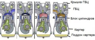
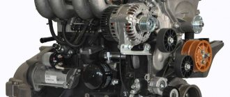
This engine was developed on the basis of the D-243 and is its turbo version. This one has the inline four cylinder cast iron engine block from the 243 with wet cast iron liners, but it gets oil jets to cool the pistons. The block has a reinforced steel crankshaft with a piston stroke of 125 mm, reinforced steel connecting rods, and new aluminum pistons with different rings were used. Oil pressure on D-245 engines (nominal speed) is 2.5-3.5 kgf/cm2. On top of the block is a modified cast iron head with different valve seats. The diameter of the valve plates is as follows: inlet - 48 mm, exhaust - 42 mm, stem diameter - 11 mm. The camshaft is installed in the block and rotates from the crankshaft through a gear; it acts on the valves using steel pushers, rods and rocker arms. Adjustment of valves on the D-245 is carried out as necessary; after every 500 hours of operation, you should check the condition of the gaps. It should be like this: inlet 0.25 mm, outlet 0.45 mm. The valve adjustment order is 1-3-4-2. Of course, it has its own intake, exhaust, fuel injection pump 4UTNI-T, a more powerful oil pump and a TKR-6 turbocharger (on the basic version).
In 1998, production of D-245 Euro-1 engines began. After another 3 years, Euro-2 versions were released, which differ in the crankshaft, pistons with a compression ratio of 17, cylinder head, YAZDA 773 fuel pump and TKR 6.1 turbine. ICE D-245 Euro-3 began to be produced in 2006 and they are distinguished by their piston, 42 mm piston pins, Common rail injection with a Bosch CP3.3 fuel pump and their own injectors. There is a TKR-6.5.1 turbine and a Bosch EDC7UC31 control unit.
In 2012, in Minsk they decided to install an EGR system and a particulate filter on the D-245, they also installed new nozzles, increased the injection pressure to 1600 bar, modified the cylinder block, increased the diameters of the main bearings, changed the connecting rods, installed a new crankshaft with different connecting rods and main journals , as well as new pistons and piston rings. In addition, it has its own camshaft and stiffer valve springs. The D-245 E4 uses a C15-505 turbine, and the engine is controlled by a Bosch EDC7UC31 ECU. To achieve the Euro-5 environmental standard, new nozzles were installed, the injection pressure was increased to 1800 bar, and the top-end D-245.35E5 has an SCR system. Such engines have been running since 2014.
Modifications of MMZ D-245 and their differences
1. D-245.1 - a motor produced since 1992 for ZiL and equipped with a TKR-6 turbine. Here the power reaches 107 hp. 2. D-245.2 - a tractor analogue of the D-245, but with an intercooler and a different fuel injection pump setting. Produced since 2000 and has a power of 120 hp. 3. D-245.4 - version of D-245 with a TKR 6-01 turbine without an intercooler with a power of 81 hp. 4. D-245.5 - analogous to D245.4, but the power is increased to 88 hp. 5. D-245.7 - diesel for buses and trucks weighing up to 8 tons. The Euro-1 version came with a TKR 60-14-3 turbine and developed 122 hp. at 2400 rpm, torque 422 Nm at 1500 rpm. Then it was modified for E2, E3, E4 and E5. Euro-2 has a TKR 60-14-02 turbine, Euro-3 has a TKR 60-14 turbine, and Euro-4 has a TKR 60.01.01-02 already installed and the power has increased to 130 hp. at 2200 rpm, torque 422 Nm at 1100-2100 rpm. 6. D-245.9 - analogous to 245.7, but with a turbine TKR 60-14-03 (Euro-1), TKR 60-14-01 (Euro-2/3) or TKR 60.01.01-03 (Euro 4), and power increased to 136 hp. at 2400 rpm, torque 446 Nm at 1600 rpm. The engine was intended for trucks and buses weighing up to 12 tons. 7. D-245.10 - engine for Bychka with 107 hp. 8. D-245.11 - modification for 107 hp. at 2400 rpm, torque 355 Nm at 1500 rpm. 4. D-245.12 - a car engine without an intercooler with a TKR-6 turbine (for Euro-1 - TKR 7N2A), which has 109 hp. 5. D-245.16 - tractor version, developing 127 hp. at 1800 rpm, torque 567 Nm at 1500 rpm. ICE was produced for the Onega Tractor Plant. 3. D-245.20 - version for ZIL with 107 hp. 4. D-245.30 - analogue of D245.7, but with a TKR 60.01.01-01 (60.01.01-05) turbine, its power is 156 hp. at 2400 rpm, and torque is 515 Nm at 1600 rpm. The modification is intended for vehicles weighing 12 and 18 tons. 4. D-245.35 - version for vehicles weighing up to 13, 18 and 21 tons. Power 170 hp at 2400 rpm, torque 595 Nm at 1500 rpm. On Euro-4 versions there is a TKR-60.01.01 turbine and the power is increased to 177 hp. at 2300 rpm, torque 650 Nm at 1200-1600 rpm. 4. D-245.42 - tractor diesel with 75 hp. at 1800 rpm, torque 365 Nm at 1400 rpm. 4. D-245.43 - another tractor version with 84 hp. at 1800 rpm, torque 411 Nm at 1400 rpm.
Engine D 245
Diesel engines D-245
and their modifications are 4
-stroke, piston, four-cylinder internal combustion engines, with a single-row, vertical cylinder arrangement, equipped with a direct fuel injection system and ignition of the fuel mixture from compression. To achieve the highest technical and economic parameters of the diesel engine, a turbocharger was added to the air intake system, with intermediate cooling of the charge air.
The use of a turbocharger in the supercharging system, with adjustable supply air pressure, makes it possible to achieve better throttle response on a diesel engine, which is ensured by an increased torque value, at a minimum crankshaft speed and a high level of compliance with the requirements for the content of harmful emissions in the exhaust gases. All models in this series are designed for normal operation at ambient temperatures ranging from −45°C to +40°C
Area of application D-245
D 245
D-245-06
-ti strong, four-cylinder, four-stroke diesel engine, water-cooled and free air inlet. Used on MTZ
series
100/102
.
( 24V
), generator
G9635.3701-01 (28V)
, pneumatic compressor
A29.05.000-BZA
, gear pump
10ZH-3-04L
, fuel pump
TNVD 4UTNI-T-1111007-400
(NZTA Noginsk), water pump, oil pump,
2
-disc clutch.
D-245.9-336
-ti strong, four-cylinder, four-stroke diesel engine, water-cooled and turbocharged. Used on MAZ-4370 “Zubrenok”
.
The engine is factory equipped with a starter 7402.3708 (24V)
, generator G9945.3701-1 (28V)
, turbocharger
TKR 6.1-03-05
(BZA Borisov), pneumatic compressor
A29.05.000-A-06
(BZA Borisov), gear pump
10ZH-3-04L
, fuel pump
PP4M10U1F-3483
(RAAZ, Roslavl) ), water pump, oil pump, single-plate clutch, without clutch housing.
Description and modifications of the MMZ D-245 engine
The MMZ 245 power unit was first developed in the early 80s and is a four-stroke engine. It was created on the basis of the earlier 240 model, and is considered its modified, improved version. Mass production of engines of this series began in 1984, and subsequently they were repeatedly refined and improved.
Despite the impressive number of modifications of this type of unit, its technical characteristics are completely the same for most versions. Among the most popular models of the MMZ D-245 internal combustion engine, it is advisable to note:
- D-245.16;
- D-245.11 E2;
- D-245.30 E2;
- D-245.9;
- D-245.35 E3 and many others.
Their main difference is the models of cars or special equipment in which they were installed. The manufacturer constantly improved the environmental performance of the units, thanks to which by 2021 the D-245.35 E5 version was released, which fully complies with Euro-5 standards.
Engine Specifications
Before studying the D 245 crankshaft, turbocharger, and other components, it is necessary to consider the technical characteristics in more detail. It is worth noting that they are completely identical for all modifications. Among them, the main parameters are the following:
- number of cylinder head cylinders - 4 pcs;
- power unit volume - 4.75 liters;
- cylinder diameter - 1.1 cm;
- type of gas exchange system - TW;
- engine power - 122.4 hp;
- type of fuel consumed - diesel;
- product weight - 600-640kg.
The engine is widely used and is used in many models of commercial trucks, various types of special equipment, and other devices.
Main engine characteristics
The four-stroke engine model D-245 is installed on brands such as the domestic Valdai and has a liquid cooling system.
Moreover, it is equipped with gas turbine supercharging. The diesel engine has a cylinder capacity of 4.75 liters and a power of 77 kilowatts.
It is also used as a power unit for wheeled tractors or road construction equipment.
Repairing a Valdai engine will take less time and effort if you contact the service on time. When dismantling a diesel engine, it is necessary to ensure the integrity of all associated parts, assemblies, and spare parts. Aggregate specialists will perform this work at the highest level using professional equipment and tools.
This design is an improved version of the old model, it is considered more powerful and reliable. However, it weighs more than 600 kilograms, which is already a reason to visit the technical center if repairs are needed.
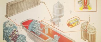
Device D-245
The design of the motor is quite simple, which greatly facilitates its repair and maintenance. The main element is the body, which includes the suspension itself and the cylinder block. The gas distribution mechanism, consisting of cylinder heads, valves, manifold and other elements, deserves special mention.
Other important components of the D-245 include:
- crank mechanism;
- lubrication system;
- fuel system;
- The unit is cooled by liquid and includes a thermostat that controls the temperature.
To improve the performance characteristics of the unit, a turbine is used in its design, which improves exhaust gas emissions and also increases torque.
To avoid the problem that is typical for all diesel injection pump engines - interruptions when starting in winter, glow plugs are installed on the cylinder heads, and the fuel system maintains the desired oil temperature.
Spare parts catalog
Having disassembled the structure of a power unit of a similar model, it is advisable to note its high maintainability. If desired, the car owner can independently purchase spare parts, for example, a starter or flywheel, and then fix the problem.
Specifications
Technical characteristics of the motor D 245:
| OPTIONS | MEANING |
| Engine weight, kg | 455 |
| Cylinder block material | cast iron |
| Supply system | direct fuel injection |
| Type | in-line |
| Working volume | 4.75 |
| Power | 122 horsepower at 2400 rpm |
| Number of cylinders | 4 |
| Number of valves per cylinder | 2 |
| Piston stroke, mm | 125 |
| Cylinder diameter, mm | 110 |
| Compression ratio | 42386 |
| Torque, Nm/rpm | 420/1400 |
| Environmental standards | EURO 3 |
| Fuel | diesel |
| Fuel consumption | 17 l/100 km combined cycle |
| Oil | SAE 10W-40 and higher |
| How much oil is in the engine | 10.7 |
| When replacing, pour | 10 liters |
| Oil change carried out, km | 25 thousand |
| Engine life, thousand km - in practice | 500+ |
The engine is installed on GAZ-3309, GAZ-33086, GAZ-33081, PAZ buses, medium-tonnage ZIL and MAZ trucks.
Main malfunctions of D-245
Most owners characterize this motor as a reliable and time-tested design that relatively rarely requires repairs. However, a fairly common problem is the unsatisfactory quality of parts processing and assembly, which leads to increased operating noise and vibration.
This problem also manifests itself in increased oil consumption, which significantly reduces the efficiency of the unit during use. In this regard, professionals recommend regularly changing seals and gaskets. If you want to extend the service life of the fuel system, in particular the fuel pump, it is recommended to promptly clean and change the diesel filter.
If you neglect such advice or use low-quality fuel, one injector or several at once may become clogged, which will lead to loss of engine performance.
Possible malfunctions of the MMZ D-245 diesel engine:
- The diesel engine does not start.
- The engine starts and stalls.
- The diesel engine stops and stalls after a period of time.
- The engine stalls under the load of powered electrical consumers.
- The engine does not develop its power (does not reach the specified operating speed).
- Oil consumption is higher than usual.
- Loud knocking noise during operation.
- Black, white and blue exhaust color.
- High fuel consumption.
- Black exhaust gases.
- Blue exhaust gases.
- The starter does not rotate, it rotates slowly.
- The electric starter does not work.
- Oil leaks on the engine body (fogging).
- Fuel leak.
- Extraneous noise when the engine is running.
- Popping sounds from the muffler during operation.
Diesel assembly D-245
Installing cylinder liners
Cylinder liners and seating surfaces of the cylinder block under the liners should be wiped with a cloth and blown with compressed air.
Install the cylinder liners into the diesel block. The protrusion of the cylinder liner flanges above the plane of the block when the liner is pressed with a force of 9±0.1 kN should be 0.05...0.11 mm. For details on installing liners, see the article - Installation of cylinder liners D-245
Laying the crankshaft
Before assembly, each crankshaft must be checked using a magnetic or ultrasonic flaw detector for the absence of micro and macrocracks, as well as for compliance of the selected set of main bearing shells with the size of the main journals. See the article in detail - Crankshaft D-245 installation
Installation of connecting rod and piston group
Check that the size group of the pistons set matches the size group of the cylinder liners.
The pistons of one set on a diesel engine must be of the same size group, corresponding to the size group of the cylinder liners.
Installation of the gas distribution mechanism
The distribution board gasket must not show any visible damage. Nicks and other mechanical damage to the treated surfaces of the distribution board are not allowed.
Installing the cylinder head and valve train
We look at installing the cylinder head in the article - Cylinder head installation D-245
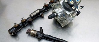
Installation of injection pump, injectors, high and low pressure pipes
The injection pump mating plate must be clean; nicks and other damage to the slab are not allowed. The fuel pump gasket must not show any visible damage. When installing the fuel pump, you must align the marks of the fuel pump drive gear and the splined flange. The splined flange of the fuel pump gear must fit freely, without jamming, onto the splines of the fuel pump shaft bushing. The fuel pump gear flange mounting bolts must be tightened to a torque of 18.25 Nm. Injectors of the same group must be installed on a diesel engine. The sealing gaskets on the side adjacent to the injectors must be lubricated with grease. The injector mounting bolts must be tightened to a torque of 20.25 Nm. High pressure pipes must be secured at a distance of 10.15 mm from the union nuts using clamps with gaskets. Low pressure fuel pipes should be purged with compressed air before installation on a diesel engine.
Installing the oil pump and power steering pump housing
Before installing the oil pump, you need to check the ease of rotation of the gears. The oil pump guide pins must fit snugly into the holes in the first main bearing cap.
Lock washers must be placed under the oil pump mounting bolts.
The lateral clearance between the teeth of the oil pump drive gears should be within 0.1. 0.65 mm.
The bolts securing the outlet pipe to the oil pump and cylinder block must be tightened to a torque of 15.25 Nm.
Before installation, the power steering pump housing must be washed and blown with compressed air. The lateral clearance between the teeth of the hydraulic pump drive gears should be within 0.08..0.2 mm.
After installation on a diesel engine, the drive housing of the hydraulic pump must be closed with a cover with a gasket. The oil pump received for diesel engine assembly must be run-in and tested. See the article in detail - Installation of the oil pump and power steering pump housing D-245
Installing the oil receiver
Before installation, the oil receiver must pass a hydraulic test with diesel fuel or an air test under pressure of 0.1 ± 0.02 MPa. Leaks, seepage or air leakage at the junction of the pipe and the flange are not allowed. Sagging and irregularities after welding must be smoothed out.
Oil sump installation
Seals must be installed in the grooves of the oil sump support before assembly. Before installing the oil pan, trim the protruding ends of the gasket between the distribution cover and the plane of the block. Before installing the gasket, the plane of contact of the oil sump to the block must be lubricated in three places with UZOM paste GOST 13489-79. Nicks and dents with a width of more than 0.1 mm on the machined surfaces of the oil sump are not allowed.
Installing the back sheet, cuff housing and crankshaft flywheel
The back sheet should fit tightly on the pins pressed into the cylinder block. The rear sheet and the interface with the crankcase, as well as the surface of the flywheel and crankshaft flange, must be wiped with a clean cloth. Paronite gaskets of the back sheet and cuff body must be lubricated with UZOM paste on both sides before installation on the pins. The mating surfaces of the flywheel and crankshaft flange must not have nicks, burrs or other damage. The flywheel mounting bolts should be tightened evenly in several steps. The final tightening of the flywheel mounting bolts should be carried out with a torque of 180.200 Nm. Installing the diesel engine support and crankshaft pulley
Defective cylinder block D-245
The cylinder block is the basis of the body part of a diesel engine and is a rigid cast iron casting
Four removable sleeves made of special cast iron are installed in the vertical bores of the block
The liner is installed in the cylinder block along two centering belts: upper and lower.
In the upper belt the liner is secured with a collar, in the lower belt it is sealed with two rubber rings placed in the grooves of the cylinder block.
The sleeves are sorted into three size groups according to their internal diameter: large (B), medium (C) and small (M).
The group marking is applied to the end of the sleeve collar. Diesel engines are equipped with sleeves of the same size group.
The diagram for measuring the internal diameter of a cylinder liner is shown in Fig. 2.
Coolant circulates between the walls of the cylinder block and the liners.
The end walls and transverse partitions of the cylinder block in the lower part have bosses designed to form the upper supports of the crankshaft.
Covers are installed on these bosses, which serve as lower supports for the crankshaft.
The bosses together with the covers form beds for the main bearings.
The beds for the main bearing shells are bored together in the assembly with the main bearing caps, so the caps cannot be swapped.
The cylinder block has a longitudinal channel, from which oil flows through transverse channels to the crankshaft main bearings and camshaft bearings.
The cylinder block in the second and fourth upper crankshaft bearings has nozzles that serve to cool the pistons with a stream of oil.
On the outer surfaces of the cylinder block there are machined mating surfaces for attaching a centrifugal oil filter, liquid pump, fine fuel filter, and oil filler neck.
The deviation from the flatness of the upper surface of the cylinder block should not exceed 0.15 mm (for a new block - 0.05 mm).
The diameter of the holes in the cylinder block for the main bearing shells when tightening the cap bolts with a torque of 190...210 Nm should be 81+0022 mm.
If the surfaces of the main bearings are worn to a diameter of more than 81.03 mm, it is recommended to restore the liner to an increased outer diameter size.
Turning over or rearranging the main bearing caps is not permitted.
The surface roughness of the holes for the main bearing shells must be Ra≤0.63 µm.
The difference in the depth of the borings for the cylinder liner collar should not exceed 0.04 mm.
The openings of the oil channels must be cleaned of dirt.
The cavity of the cylinder block, washed by coolant, and the oil channels must be checked for leaks using water under a pressure of at least 0.4 MPa for 1 minute.
Untreated surfaces must be coated with a primer.
When pressing in the front, middle and rear camshaft bushings, the oil holes in the bushing and the block must be aligned.
The rear camshaft bushing must be pressed into the block to a depth of 7 mm relative to the rear plane, and the front one must be flush with the front plane of the block.
The bushings must be pressed in using a set of special mandrels (Fig. 3).
The deviation from the flatness of the mating surface of the oil sump should not exceed 0.25 mm.
When testing the oil sump with liquid under a pressure of at least 0.1 MPa, leakage or the appearance of drops over the entire surface is not allowed.
The deviation from the flatness of surfaces “A” and (Fig. 4) of the front diesel support should not exceed 0.1 mm.
The deviation from parallelism of surfaces “B” relative to surface “A” should not exceed 0.2 mm over a length of 100 mm.
Surfaces “B” must lie in the same plane;
The riveted part of the limiter should not protrude above the plane of the shock absorber plate by more than 0.5 mm.
The shock absorber rubber should not have cracks or tears.
When the shock absorber is compressed with a force of 2 kN, its height deformation should be 2.5 ± 0.5 mm.
Mounting mating of body parts