Full check of the diode bridge
You can also check the diode bridge with a multimeter according to the following instructions:
- We set the red probe to “–”, and touch the black terminals in turn to which the alternating voltage is connected “
", in both cases there should be about 500 on the device screen. We put the black probe on “–”, touch the red terminals “
or AC”, the multimeter display shows one, which means the diodes do not conduct in the opposite direction. The first half of the diode bridge is working.
The black probe is on “+”, and with the red one we touch the AC voltage inputs, the results should be the same as in point 1. We swap the probes, repeat the measurements, the results should be the same as in step 2.
The same can be done with a “tseshka” (a Soviet-made universal measuring device). How to check a diode bridge with a dial multimeter is described in the video:
By the way, the test can be performed without a tester at all - with a battery and a test light (or LED). When the diode is turned on correctly, current will flow through the light bulb and it will light up.
In conclusion, I would like to note that diode bridges are installed everywhere: in the charger, welding machine, on the inverter, in power supplies, etc. Thanks to the described method, you can test diodes for performance at home.
It will be useful to read:
Electronics today are an integral part of any mobile gadget, household appliance or vehicle. Often the cause of a breakdown is the failure of a semiconductor - a small element of the electronic “filling”. Checking the diode allows you to understand whether this conductor is working or needs to be replaced.
You can perform such manipulations yourself at home without the involvement of a specialist. To do this, you will need knowledge of the basics of electrical engineering and a special measuring device - a multimeter. In the case where the diode cannot be removed from the circuit, you will have to be creative and create a device adapted for these conditions.
Why does the diode bridge burn out?
There are several reasons for the failure of the diode bridge on VAZ cars. To prevent the breakdown from occurring again, you need to check the machine for one of the options described below. Only by eliminating the problem can normal operation be ensured.
Most often, a bridge burns down due to the following:
The diode bridge, like any spare part, has its own service life. It usually lasts about 10 years, after which the unit may fail due to normal wear and tear.
It is best to periodically diagnose the car, check the serviceability of the main components and conduct an inspection to identify problems when they are not yet fatal. It is recommended to check the battery annually and measure the charge level to monitor the condition of the generator.
The simplest and roughest check
We will need an indicator screwdriver. It costs pennies and should be in every home's toolbox. You just need to first touch the 220V input of the rectifier, if the indicator on the phase wire lights up, then voltage is present, if not, the problem is clearly not in the diode bridge and you need to check the cable. If there is voltage at the input, check the voltage at the positive output of the rectifier; at this point it can reach up to 310 V, the indicator will show it to you. If the indicator does not light, the diode bridge is broken.
Unfortunately, we won’t be able to find out anything else using an indicator screwdriver. You can learn how to use an indicator screwdriver from our article.
Multimeter
Testing with a tester allows you to determine the serviceability of the diode or confirm its failure. The most commonly used measuring instrument in this area is the multimeter. It is used to measure all the main parameters of electrical circuit components: current, voltage, resistance, capacitance. More expensive models are able to measure the temperature of an object, find out the gain, the capacitance of capacitors, and test the circuit for a short circuit.
Almost all modern types of multimeter can work with both constant and sinusoidal types of electric current. Among the devices on the market, digital and analog types are the most in demand. And although the first type is more popular, the second is still actively used by professionals in their work.
The main advantages of classic analog multimeters are their reliability and low cost (compared to digital ones). However, the minus manifests itself in less accuracy, allowing an error of 1.5-2%.
Digital devices are often used at home. They are more accurate (accuracy up to 0.5%), easy to operate and have greater measurement resolution.
These testers do not require calibration before each measurement and are resistant to vibration.
There is a third type whose device includes both a pointer and a digital indicator.
In addition to the main body, the tester comes with 2 probes with red and black wires.
At the bottom of the instrument panel you can see several connectors:
- “COM” - common, grounded (for black probe);
- “VΩmA” - a connector that allows you to ring the contacts, measure the current strength and frequency (for the red probe);
- “10 A” is a socket for a wire that allows you to measure current up to 10A.
The fourth “°C mA Lx” socket, present on some models, measures additional parameters (temperature, gain and capacitance).
Also on the front panel you can see a rotary disk surrounded by a scale with digital values and marks. Using this dial, you can set the required values, configure them to the desired modes or perform certain functions.
How to check without dismantling
You can diagnose the device on site without disassembling the generator or desoldering the part. To do this, unscrew all the wires on the generator and voltage regulator, set the tester to ohmmeter mode, and connect the lamp to the battery in the manner described above.
This method allows you to check the serviceability of the entire bridge and individual groups.
Short circuit
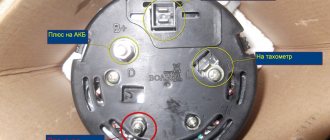
For this test, the positive electrode is applied to output 30 of the generator (“plus” of the power rectifier), and the negative electrode is applied to the housing. A resistance value of 1 indicates that the bridge is in good condition.
One end of the lamp is connected to the negative terminal of the generator, the other to the positive terminal. A lit lamp indicates a short circuit.
Negative group
The negative electrode of the tester is connected to the frame of the generator, the positive electrode is connected to one of the diode bridge mounting bolts. The negative group is operational if the resistance is infinity.
To check with a lamp, connect its minus to the generator casing, and the plus to the axle mounting bolt. The lamp lights up or flashes when there is a malfunction in the negative group of elements.
Positive
The positive probe of the multimeter is connected to the positive terminal, the negative one to the bridge mounting bolt. With a working group, the resistance is infinite.
The negative of the lamp is connected to the bridge mounting bolt, the plus is applied to the positive terminal. A lit lamp indicates a short circuit in the positive semiconductors.
Minor group
The positive electrode of the tester is pressed to terminal 61 (usually the “plus” of the additional rectifier), the negative electrode is connected to any bridge mounting bolt. The diodes are serviceable with a resistance value of 1.
The negative end of the lamp is connected to the bridge mounting bolt, and the positive end is connected to terminal 61. A lit lamp indicates a malfunction in this group.
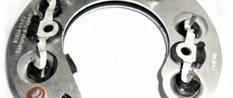
Bridges can be made of individual diodes or made as a monolithic structure (diode assembly)
How to check the voltage regulator
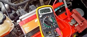
The regulator is checked in case of undercharging or overcharging of the battery. The voltage is measured at rpm; it should be in the range of 14.4 - 15V.
In addition, you can check the resistance of the regulator capacitor (at the moment the tester probes are connected, it should decrease until it approaches infinity).
With the generator voltage regulator removed, the condition of the brushes is inspected and serviceability is checked using a 12V light bulb and constant voltage. That is, you need to connect a light bulb to the brushes, and apply 12V to the positive terminal and ground of the regulator (the light bulb should be on, and go out when the voltage increases above 15V).
Checking a conventional diode bridge
As written above, the diode bridge consists of four separate semiconductor diodes. To check its serviceability, we need to ring each of them in two directions. We turn the multimeter into test mode (it is marked with a diode or sound icon) and select the first diode with which we will begin the test.
We find its anode (positive terminal) and cathode (negative terminal). Usually they are indicated on the diode body using a color designation or corresponding icons. First, we check the diode in direct connection; to do this, we connect the red probe (positive) to the anode, and the black probe (negative) to the cathode.
Numbers should appear on the multimeter display - the value of the voltage drop, it is indicated in millivolts. This is the minimum voltage that is needed to open the diode.
Now let's check it in reverse connection, to do this we swap the probes - red to the cathode, and black to the anode. The display should show one, which indicates to us that the PN junction has a high resistance - this diode is working.
If the reverse connection shows low resistance, and the device beeps (with an audio indication), this diode is broken and needs to be replaced. Thus, we call the remaining three pieces and if a faulty one is found, we simply unsolder it and replace it with a new one.
Testing the diode bridge with a multimeter
Any part on the board can be desoldered for testing or ringing without desoldering. However, the accuracy of the check in this case is reduced, because perhaps a lack of contact with the board tracks, with visible “normal” soldering, the influence of other circuit elements. This also applies to the diode bridge; you don’t have to desolder it, but it’s better and more convenient to desolder it for testing. A bridge assembled from individual diodes is quite convenient to check on the board.
Almost every modern multimeter has a diode test mode, usually it is combined with an audio continuity test of the circuit.
This mode displays the voltage drop in millivolts between the probes. If the red probe is connected to the anode of the diode and the black probe to the cathode, this connection is called forward or conductive. In this case, the voltage drop across the PN junction of the silicon diode is in the range of 500-750 mV, which you can see in the picture. By the way, it shows a test in resistance measurement mode, this is also possible, but there is also a special diode test mode, the results will be, in principle, similar.
Read also: Soft start for an angle grinder connection diagram
If you swap the probes - red to the cathode, and black to the anode, the screen will show either one or a value of more than 1000 (about 1500). Such measurements indicate that the diode is working; if the measurements differ in one of the directions, then the diode is faulty. For example, if the continuity test is triggered - the diode is broken, there are high values in both directions (as with reverse switching on) - the diode is broken.
Important! Schottky diodes have a lower voltage drop, about 300 mV.
There is also an express check of the diode bridge with a multimeter. The procedure is as follows:
- We place probes at the input of the diode bridge (
or AC), if the bell is triggered, it is broken.
- We put the red probe on “–”, and the red one on “+” - a value of about 1000 appears on the screen, swap the probes - on the screen 1 or 0L, or another high value - the diode bridge is working. The logic of this test is that the diodes are connected in series in two branches, pay attention to the diagram, and they conduct current. If the positive power supply is applied to – (anode connection point), and the power supply minus is applied to “+” (cathode connection point), this is what happens during dialing. If one of the diodes is broken, current may flow through the other branch and you may make erroneous measurements. But if one of the diodes is broken, the voltage drop across one diode will be displayed on the screen.
The video below clearly shows how to check a diode bridge with a multimeter:
Operating principle of generator and diode
A generator is a device used to convert mechanical energy supplied from an engine into electrical energy. If it malfunctions, the following problems occur:
- headlights become dim;
- The battery charge signal lights up continuously;
- an extraneous sound is heard in the area where the generator is located;
- The analog needle of the voltmeter goes into the red zone.
Since the generator is directly connected to the charging circuit, the primary signs of a malfunction of the rectifier will be an overcharge or complete lack of charge of the battery. If such problems appear, the generator requires checking.
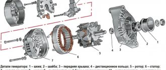
The output generator produces a sinusoidal signal, but devices located in the car require constant voltage. To generate a constant signal, a rectifier unit is built into the generator. It consists of six power diodes.
A diode is a semiconductor element with a pair of leads, electrodes. The principle of its operation is based on the ability to pass current in one direction. If the positive polarity of the signal is supplied to the p region of the device, and the negative polarity to the n region, then such a connection is called direct. If the polarity is reversed, then this is reverse connection.
In direct connection, the resistance of the pn junction is negligible and does not affect the passage of electric current, and when connected in reverse, it practically does not allow it to pass.
Principle of operation
The operation of a diode semiconductor bridge that conducts current is simple. The principle of operation is based on the property that a semiconductor diode passes electric current in one direction and does not pass in the other. So, if the charges are connected correctly, current will flow through the device.
The difference between alternating current and direct current is that it can only move in one direction. Moreover, do this in one half-cycle. During the other half of the period, it can make the opposite movement. When several diodes are connected in a circuit, they will begin to move, creating a direct current.
You might be interested in this: Features of three-phase current
It is easy to assemble a diode bridge circuit. Anyone can do this. It includes four diodes, which are connected to each other by a square. Current is supplied to several opposite corners from the generator apparatus. From several other opposite angles the constant is removed. During the first period, several electrodiodes are opened and the alternating voltage wave is rectified. In the second period, several more diodes are opened. Thus, the second wave is transformed. The result is a constant voltage with a pulse frequency several times higher than that with alternating voltage.
Interesting! The presented scheme has its pros and cons. To use rectified current, the pulse component must be smoothed with a filter. Thanks to rectification, it is possible to power the transformer and reduce its volume. Among the disadvantages, note the fact that power is lost due to thermal dissipation, the voltage drops twice and the device breaks down if one diode fails.
How the device works
Features of testing depending on the type of diode
In the production of modern radio-electronic devices, several types of diodes are used:
- regular or protective;
- LEDs;
- Schottky diodes;
- Zener diodes;
- thyristors and triacs;
- infrared;
- photodiodes.
Protection diodes can be found in most modern household appliances. They are common and are the simplest elements of circuits for electric kettles, fans, blenders and other devices that make life easier.
The area of application of LEDs is the well-known lamps. They are divided into devices such as household and street lighting. Schottky diodes are used in assembling computer power supplies, and the main task of zener diodes is to protect devices from voltage surges, in other words, to stabilize them.
Diodes such as thyristors ensure smooth engine starting. They are actively used in the automotive industry. Triacs can pass current in two different directions.
Infrared ones are built into remote control panels and optical control and measuring instruments. Photodiodes convert the light that hits the sensitive board into an electrical signal. They are also used in organizing street lighting systems.
A multimeter is most often used to measure the characteristics of LEDs, conventional semiconductors and Schottky diodes. Testing of all these types is carried out by the tester in accordance with the same principle.
The main reasons for the malfunction of such semiconductors are:
- Exceeding the maximum permissible level of electric current.
- Poor quality parts or manufacturing defects.
- High reverse voltage.
- Violation of the operating instructions for the device.
Diagnostics is performed using a special device designed for this purpose - a multimeter.
What is a generator diode bridge and what functions does it perform?
The rectifier unit (another name for the device) is an integral part of the generator and serves to modify the alternating current produced by the unit into direct current, necessary for charging the battery and powering all electrical appliances of the car.
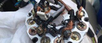
It is located on the frame of the generator and consists of 4, 6, 9 or more diodes placed on two insulated aluminum or steel horseshoe plates that act as cooling radiators.
The main components of the bridge are semiconductor diodes (most often silicon) that conduct current in the required direction. They are the rectifiers that convert alternating current into direct current. The battery acts as a capacitor, softening the inevitable voltage drops.
Instead of diodes, the circuit can use valves of any type - for example, selenium columns, the principle of operation of the circuit will not change.
What you need to know about diode bridges
First, we will look at what they are and what is inside a diode bridge. These circuit elements are available in two versions:
- From discrete (separate) diodes. Usually soldered on the board and connected by tracks in the correct circuit.
- Diode assemblies. The assemblies can be either single-phase bridges for rectifying both half-cycles of alternating voltage, or assemblies of two diodes connected in a circuit by a common cathode or anode, and other connection options.
In any case, the rectifier single-phase diode bridge consists of four semiconductor diodes connected to each other in a series-parallel manner. Alternating voltage is supplied to two points at which the anode and cathode are connected (opposite poles of the diodes). Constant voltage is removed from the connection points of like poles: plus from the cathodes, minus from the anodes.
In the diagram, the connection point for alternating voltage is indicated by the symbols AC or “~”, and the outputs with constant voltage are “+” and “-“. Draw this diagram for yourself, it will be useful to us when checking.
If you imagine a real diode bridge and combine it with this circuit, you get something like:
Video: operating principle of a diode bridge
How to check a diode bridge: known methods
Before checking the diode bridge with a multimeter or autotester, familiarize yourself with the principle of operation of the circuit. A modern diode bridge has 3 positive, negative and additional diodes. The working element passes current in one direction. If the current does not pass or passes in both directions, then a break or “breakdown” has occurred.
The diode bridge is tested using a tester (called a multimeter). First you need to disconnect all wires from the generator. The check does not require dismantling the device itself unless you check the integrity of each diode individually.
Next, the diode bridge is analyzed with a multimeter in accordance with the data given in the table:
If the multimeter shows infinite resistance, then the device or group of diodes being tested is working. Otherwise, the check indicates a breakdown.
Checking a car diode bridge with a multimeter is not the only possible diagnostic method. You can also use a test light or check the bridge with a self-assembled analogue.
Using a test lamp, we make calls in the same way as with a multimeter. The unit is fully checked by connecting the “plus” through the lamp to pin 30, the “minus” - to the generator housing. For groups of diodes:
- Positive: “plus” with a test lamp is supplied to pin 30, “minus” - to one of the mounting bolts.
- Negative: “plus” with a light bulb – on the mounting bolt of the electrical component, “minus” – on the generator housing.
- Additional: a light bulb with a “positive” wire is connected to pin 61, a “minus” wire is connected to the mounting bolt.
If the control light comes on when the circuit is closed, then there is a malfunction; If it doesn’t light up, the circuit is working.
If necessary, you can, of course, test all diodes individually, but this will require unsoldering each diode.
Instructions for verification
Verification is carried out using several methods. This is done with the assistance of a multimeter and a lamp. With the first method, measurements are more accurate and safe. However, if the multimeter malfunctions, you can use a flashlight lamp with a voltage of 12 volts. After choosing the measurement method and finding the diode bridge, you need to inspect the entire board.
12 volt flashlight lamp for checking the bridge
Elements must have a natural color and no charring or decay. You also need to look at the place where the soldering and tracks are located. It is important that there are no broken or sealed parts. It is also necessary to inspect electrolytic capacitor barrels. They should appear undamaged and unswollen. If a capacitor swells and explodes, it is necessary to desolder it. All the same, this part needs to be replaced and will interfere with measurements. If a capacitor explodes, after desoldering it is necessary to thoroughly wash the board with alcohol, since parts of this element are acidic electrolytes that conduct current.
You may be interested in this All about free energy
Next, you need to carry out a continuity test of the diode bridge. It is carried out in several stages. First, on the spot without desoldering, then more precisely with desoldering the circuit from the device. As a rule, in many cases only on-site testing is required. To work, you should take a dial or digital multimeter and set the resistance measurement mode to 1 kOhm.
Note! In the case of a digital multimeter, you need to set it to diode test mode. In each case, the result of the normal voltage is as follows: up to 200 and 700 Ohms.
Checking the bridge with a multimeter
Using a generator tester
You can check the diode bridge on the generator by performing the following steps:
- Unsolder the bridge from the generator and check each diode with a multimeter at a resistance mode of 1 kOhm;
- Bring the probes to the diode edges and take a measurement;
- Apply the probes to the diode edges in the opposite order and take another measurement after 10 minutes.
In addition to the topic of how to check the diode bridge of a generator with a multimeter, it should be noted that its negative and positive contacts work properly when outputting values up to 700 Ohms. If the value is less than 500 Ohm or the infinity sign, this indicates a hardware malfunction.
Testing the bridge with a generator lamp
If you don’t have a multimeter, you can check the diode bridge using a light bulb and battery. You need to take a battery or a cassette with 12 volt batteries, as well as an incandescent lamp that matches the voltage of the batteries. It should be selected low-power. Otherwise, you can burn the diode bridge with current. A light bulb from a flashlight or sidelights may be suitable for measurement. Next, you need to act as indicated by the diode bridge test circuit.
Scheme for checking a bridge using a generator lamp
According to the diagram steps on the left, you need to install the diode in the forward direction. At this moment the light should light up. This is a key sign of normal operation. According to the right diagram, the light bulb should not light up. All you need to do is assemble the tester and probes, ring the bridge and look at the lamp.
Note! If the light comes on, this indicates low resistance. If not, then it matters a lot.
Causes of diode bridge failure and its symptoms
The diode bridge of the generator is structurally designed as a separate module. The forming elements may fail during ongoing operation. This happens for the following reasons:
- moisture entering the electrical circuit when washing a car or engine;
- penetration of dirt and oil into the generator housing with broken seals (occurs when driving at high speed on dirt roads);
- reversing the polarity of the battery contacts while “lighting” another car.
Indirect signs of bridge failure are manifested in the fact that
- the voltage at the generator output does not exceed 13.5 V or the ammeter needle is in the red sector;
- spark power decreases;
- the brightness of the headlights changes noticeably with changes in engine speed;
- the performance of the cooling system fan decreases;
- the starter does not develop the required number of revolutions;
- the normal functioning of the on-board air conditioning is disrupted.
Main signs indicating a faulty diode bridge
A normally operating diode conducts current in only one direction. In the event of a breakdown, a current leak appears, which flows from the on-board network to the starter windings. Today, several types of diode bridges are installed on cars:
- diode bridge without additional cooling;
- diode bridge with passive cooling due to special radiators.
In addition, there are different types of connecting windings and connecting bridge platforms: using welding or soldering. The first sign that the generator is operating unstably due to a broken diode bridge is the rapid and frequent discharge of the battery. There are other reasons why you can indirectly determine the combustion of diodes in a rectifier:
- insufficient spark on the spark plugs;
- headlights with dim light during operation of the power unit;
- interruptions in the sound system;
- significant reduction in cooling fan power;
- poor operation of the air conditioning system.
If any of the above-mentioned signs are noticed, there is no need to panic, but it is better to find out why the diodes burned out, for which you should seek help from the service station specialists.
Location of the diode bridge on the board and precautions
Diode bridges are installed in power supplies, both pulse and transformer. It is worth noting that in pulse units, which are now used in all household appliances, the bridge is installed at the 220V input. At its output, the voltage reaches 310V - this is the amplitude voltage of the network. In transformer power supplies they are installed in the secondary winding circuit, usually with a reduced voltage.
If the device does not work and you find a blown fuse, do not rush to turn on the device after replacing it. Firstly, if there are problems on the board, the fuse will burn again. This power supply must be turned on via a light bulb.
To do this, take a socket and screw a 40-100 W incandescent lamp into it and connect it to the phase wire to connect to the network. If you are going to frequently repair power supplies, you can make an extension cord with a socket installed in the gap in the power wire to connect the lamp, this will help save your time.
If there is a short circuit on the board, when connected to the network, a high current will flow through it, a fuse or a track on the board, or a wire will blow, or the machine will trip. But if we insert a light bulb into the gap, the resistance of the spiral of which will limit the current, it will light up at full intensity, maintaining the integrity of all of the above.
If there is no short circuit or the unit is working properly, either a slight glow of the lamp or its complete absence is acceptable.
How to determine generator malfunctions
Signs of a faulty generator diode bridge. A car generator and a generator, a household power station are similar. Accordingly, the principles of troubleshooting and repair are the same. The only difference is that the car generator contains a rectifier and a voltage regulator, so the car network is designed for 12 Volts. The article discusses generator malfunctions and how you can fix them yourself. Your vehicle is equipped with a warning light that can alert you that the alternator has lost power. If this happens, you need to make sure that the sensor is working and the lamp is connected correctly.
It often happens that these lamps use a bad connector or the control relay fails. It is also possible that your battery, charging terminals are faulty, or it is simply discharged. When there is a lot of energy consumption, for example, when using lighting devices to the maximum, charging, or leaving the radio on overnight. Generator malfunctions may occur due to increased energy production when the voltage is above 14-15 Volts. The numbers vary depending on the model.
Therefore, if the battery breaks down, you should always check the generator too. Sometimes the generator begins to deliver current below the required limit of 13.2 Volts, then it is urgently necessary to check it for damage.
Do not forget that the optimal number of revolutions for the generator is 2000-2500. If one of these points applies to your case, then contact the service or conduct an independent diagnosis of the generator malfunction.
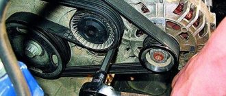
Before removing the generator, it is necessary to check the tension of the drive belt. Lack of electrically conductive connections between the battery or generator and the car body; voltage may be lost “on the way” to the battery. Also check the bearings for clearances and the integrity of the fuses.
For some types of faults there is no need to remove the generator. If there are knocks or noise during work, it is necessary to disconnect the wires: the noise will disappear - but a short circuit will form, unfortunately, these are expensive repairs, their cost exceeds the price of new equipment.
The noise remains - replace the bearings, they have worn out during use. Check the brushes, maybe it's time to replace them too. The contact brushes and rings may not be pressed well, then the spring should be adjusted. Get rid of dirt and burnt marks on the rings, if any. Sandpaper is the best way to remove scorch marks. If the rings become unusable, the rotor must be replaced. Check the rotor contacts with a multimeter.
Generator malfunctions in the form of a damaged rotor must be removed in the following order. Since a faulty rotor cannot be replaced, it must be completely replaced if it fails. The same applies to the stator. Remember that the rotor and stator must not have electrically conductive contact with the body or other parts of the vehicle. A faulty stator must be replaced. Voltage rectifier diodes should not conduct current in both directions.
- Signs of a generator malfunction
- 1. What is a generator?
- 2. What are the generator malfunctions and how can they be eliminated?
- 3. Self-diagnosis, or how to figure out generator problems
A car's generator is a very significant element of its design, which, together with the car's battery, provides many important components of the vehicle with the necessary electricity. Thus, thanks to the energy received from the generator, the ignition system, lighting devices and various electronic devices, of which there are quite a lot in a modern car, operate. Of course, even the slightest malfunction of the generator will affect the operating efficiency of any electrical appliances on the machine, up to the point of completely blocking their activity.
Therefore, it is advisable for the car owner to have at least a general understanding of the main causes of generator problems, their characteristic symptoms, diagnostic and elimination methods.
What is a generator?
A car generator is a device responsible for converting mechanical energy received from the engine crankshaft into its electrical version.
The first generator “saw” the world in 1832, and its “parents” were the Parisian technical scientists - the Pixie brothers.
Of course, at that time such a design was far from perfect, and it was difficult to use. To operate such a machine, people were forced to rotate a heavy permanent magnet, which created an alternating electric current on two wire coils fixed near its poles. This generator had a device for equalizing the current, and to increase the power of electrical machines, scientists of those times began to increase the number of magnets and coils.
Features of diodes
A standard diode is a component of the electrical network and acts as a pn junction semiconductor. Its structure allows current to pass through the circuit in only one direction - from the anode to the cathode (different ends of the part). To do this, you need to apply “+” to the anode and “-” to the cathode. Due to this feature of the product, if you suspect a breakdown, it can be checked with a tester or multimeter.
Various types of diodes.
Today in radio electronics there are several types of diodes: Types of diodes:
- Light-emitting diode. When an electric current passes through such an element, it begins to glow as a result of the transformation of energy into a visible glow;
- protective or regular diode. Such elements in the electrical network act as a suppressor or voltage limiter. One of the varieties of this element is the Schottky diode. It is also called a Schottky barrier diode. Such an element, when connected directly, gives a low voltage drop. In Schottky, instead of a pn junction, a metal-semiconductor junction is used.
Here is a small selection made up of specific diodes and their corresponding Vf values, which were obtained when testing them with a multimeter. All diodes were previously checked for serviceability.
Table of measurements of diode characteristics using a multimeter.
If ordinary parts and LEDs are used in the vast majority of electrical appliances, then Schottky ones are used mainly in high-quality power supplies (for example, for devices such as computers). It is worth noting that testing a conventional diode and a Schottky diode is practically no different, since it is carried out according to the same principle. Therefore, there is no need to worry about this issue, because the operating principle of both Schottky and conventional diodes is identical.
Schottky diode
Being a component of an electronic circuit, such semiconductor elements often fail. The most common reasons for their failure are:
- exceeding the maximum permissible direct current level;
- excess reverse voltage;
- poor quality part;
- violation of the device operating rules established by the manufacturer.
Moreover, regardless of the cause of loss of performance, failure can be directly caused by either a “breakdown” or a short circuit. In any case, if there is an assumption that the electrical network has failed in the semiconductor area, it is necessary to diagnose it using a special device - a multimeter. Only to carry out such manipulations you need to know how to check the diode using it correctly.
What is a multimeter
A multimeter is a universal device that performs a number of functions:
- measures voltage;
- determines resistance;
- checks wires for breaks.
Using this device you can even determine the suitability of the battery.
Checking the LEDs in the lamp.
How to test a diode
After we have figured out the semiconductors of the electrical circuit and the purpose of the device, we can answer the question “how to check the diode for serviceability?” The whole point of checking diodes with a multimeter is their one-way electrical current carrying capacity. If this rule is observed, the electrical circuit element is considered to function correctly and without failures. Conventional diodes and Schottky diodes can be easily tested using this device. To check this semiconductor element with a multimeter, you need to do the following manipulations:
- you need to make sure that your multimeter has a diode test function;
- If such a function is available, we connect the probes of the device to the side of the semiconductor from which the “ringing” will be carried out. If this function is missing, then use the switch to switch the device to 1 kOhm. You should also select the mode for measuring resistance;
- the red wire of the measuring device must be connected to the anode end, and the black wire to the cathode end;
- after this, you need to observe changes in the forward resistance of the semiconductor;
- we draw conclusions about the presence or absence of voltage
The unit can then be switched to check for leaks or high circuits. To do this, you need to change the location of the diode output. In this state, it is also necessary to evaluate the obtained values of the device.
How is the check carried out?
To check a semiconductor using a tester, you need to make sure that the multimeter has a diode test mode. After this, the work algorithm will be as follows:
- the red probe is inserted into the socket marked “VΩmA”;
- black – to the “COM” connector;
- select the mode for measuring resistance;
- the end of the red probe is connected to the anode, and the black one to the cathode;
- readings of changes in direct resistance are taken.
After all the operations performed, we can draw a conclusion about the performance of the semiconductor.
Checking the diode bridge
In a number of situations, it is necessary to check the condition of the diode bridge. It is a system of 4 diodes connected in such a way that the alternating voltage supplied to the two soldered components is converted to direct voltage.
The measurement algorithm is very similar to the classic method for testing a diode. However, there are also some nuances, namely the presence of 4 connection options depending on the pin number. The following combinations are usually called:
Analysis of results
Having received the test result, we can conclude that the semiconductor is serviceable. Signs of diode performance are:
- Coincidence of the forward voltage value displayed on the display when the element is connected to the tester with the indicators for a given type of diode.
- The zero value produced by the multimeter when connected in reverse.
Important! The voltage level of the semiconductor depends, among other things, on the type of diode, which must be taken into account during measurements.
If these parameters are observed, one can judge the working condition of the diode and the presence of a breakdown elsewhere. If one of the indicators does not meet the requirements, the semiconductor is considered non-working and must be replaced.
Checking diodes for serviceability using a tester is not so difficult on your own. A large assortment of multimeters on the market will allow you to choose a completely budget model, which will allow you to assess the performance of the diode in the circuit of any household electrical appliance.
How to test a diode with a multimeter without unsoldering it
Checking the Schottky diode is carried out without unsoldering it from the circuit, since this type of semiconductor is placed in a double case with a common cathode. So the measurement in this case can be done “on the spot”.
Read also: How to properly solder plastic pipes
The same difficulties can arise when checking an LED. In some cases, it is necessary to evaluate a semiconductor without soldering it. Standard multimeter probes are not suitable for this, so you will have to make a special device that allows you to reach the electrodes in the circuit.
All work will include the following operations:
- On each side of a small foil fragment of PCB it is necessary to apply a small amount of solder on which the wires will be fixed.
- Straighten paper clips or small pieces of steel wire, which will then be soldered to the textolite gasket. Secure the entire structure with electrical tape.
- Prepare a multimeter with transistor testing mode.
- Connect the designed adapter to the tester.
- Place the probes on the legs of the semiconductor located in the circuit.
- To inspect.
Checking with a light bulb
To implement this method, you need a 12-volt low-power light bulb and three wires 1 meter long. Two of them are used to form the indicator cord. To do this, they are first connected to the contacts of the light bulb, which as a result ends up in their gap. The third wire connects one of the battery contacts to the bridge.
To check the circuit, the bridge body is connected to the battery negative with a third wire. Then one end of the indicator cord is connected to the negative terminal of the bridge, and the other end is connected to pin 30 of the bridge. The light coming on is a sign of a breakdown of the bridge, and its absence indicates a break.
To check the negative diodes, the minus voltage of the battery is applied to the bridge body. The plus of the battery is connected with an indicator cord to the fixing screw of the bridge. If the lamp lights up, it indicates a breakdown; its absence indicates a break. Testing positive diodes begins by applying the battery positive to terminal 30, and the negative is connected through the indicator cord to the bridge mounting screw. If the diodes are working properly, the lamp does not light up.
Something else useful for you:
- How to check and replace the alternator belt on a car
- Replacing the alternator belt on a Renault Logan with power steering and air conditioning
- How to quickly and easily check the generator relay regulator
Checking the generator on the car
First of all, you need to see if the alternator belt is intact. If it is not torn, then the belt tension is checked. Then it's time for the battery. Using a tester (multimeter), we measure the voltage at the terminals. It should be around 12−12.7 volts. If everything is fine, start the engine. If the battery is discharged, charge it and start the engine again.
We measure the voltage at the battery terminals. It should be within specified limits, usually from 13.2 to 14.5 volts. But on modern cars these limits may differ. If you have an instruction manual, you can read it. Deviation from the specified values in any direction is a malfunction. These deviations can be of three types:
- Lack of charging current - the generator does not work.
- There is a charging current, but below the minimum value -
- Voltage above the maximum value means the battery is overcharged.
All three cases indicate an existing malfunction in the vehicle's electrical supply system. it is necessary to carry out a comprehensive check of the generator.
But before that, conduct a visual inspection of all the wires and cables that go from the generator to the battery. There should be no visible damage, breaks or oxidation of the electrical wiring. Be sure to check the terminals on the battery, starter and alternator. They must be clean and dry. Any oxidation, rust or dirt must be cleaned off. Often this helps restore lost contact and the car begins to work as expected. If this does not help, we proceed to a detailed check.
Using a Multimeter
For further inspection, it is better to remove the generator from the car. First of all, remove the relay regulator from the generator and check it. To check the voltage stabilizer, you will need a multimeter and a charger with regulated voltage. It would be better to use a power supply instead of a charger. Voltage adjustment from 0 to 16 volts will be sufficient.
Connect the plus of the power supply to the regulator - usually this is a male plug connection. Hook the minus to the minus, it is usually output to the ear of the relay mount. Connect the red wire of the tester to the positive wire of the power supply, the black wire to the negative wire. Connect two stripped wires to the brushes, one for each. A light bulb is connected to the other pre-stripped ends (it can be removed from the rear lights of the car during testing). The test bench is ready.
Continuity of the relay regulator
Connect the power supply to the network, carefully use the regulator knob to begin raising the voltage. At the same time, monitor the multimeter readings. The light bulb should not light up at the very beginning, but as the voltage rises it should light up, first at half-incandescence and as the voltage increases, the brightness should increase.
When the 14.5 volt mark is reached, the regulator should operate, cutting off the voltage. The light should then go out. It is generally accepted that the stabilizer is working if it cuts off the current at values from 14.2 to 14.8 volts. If this happens at lower or higher values, then the voltage regulator is faulty. The relay is also faulty if there is no current cutoff at all.
If the relay malfunctions, replace it with a new one. If it is working properly, we continue checking.
Checking with a multimeter
The multimeter switches to resistance measurement mode (range 1 - 2 kOhm) or continuity with a sound signal. Before starting work, touching the contacts of the probes to each other controls the choice of the desired mode (reading 0 kOhm or sound signal, respectively).
Bridge diodes are divided into two types, conventionally called positive and negative. Positive diodes have a red body, and negative diodes have a black body. All diodes must be checked individually.
During the test, the multimeter probes are touched to the diode outputs and the result is recorded, then the probes are swapped. For a working diode, the resistance should be in the range of 400 - 800 Ohms in one position of the probes and become equal to infinity for a given range in another (the presence of a buzzer in the first case and its absence in the second).
If there is a different combination of test results (small + small or large + large resistance according to the indicator, or sound + sound, no sound + no sound), the diode is considered to be faulty.