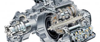
Rear axle DT-75
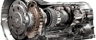
The DT-75 rear axle is two main units combined into one unit: the main gear and the planetary turning mechanism of the tractor. With the help of these units, torque from the engine is transmitted to the final gears and the tractor is braked and turned. Both units are placed in the rear of the transmission housing, which has three compartments separated by partitions. The side (outer) compartments contain the stopping brakes and sun gear brakes, and the middle compartment houses the planetary rotation mechanism and the main gear.
The device of the main components
The main gear consists of two bevel gears: drive and driven. The drive gear and the secondary shaft of the gearbox are made as a single unit, and the driven gear is bolted to the ring gear flange located in the middle compartment of the planetary rotation mechanism. Adjustment of the gaps between the drive and driven gears, as well as between the flange and the driven gear, is carried out using shims.
The ring gear of the planetary mechanism rotates on ball bearings, which are pressed into bores on both sides of the gear. In this case, the internal races of the bearings are placed in cups, the flanges of which are bolted to the partitions of the middle compartment of the transmission housing of the DT-75 rear axle.
Inside the ring gear there is a planetary mechanism, with the help of which the transmission of rotation to one of the tracks is slowed down or completely stopped, and thus the tractor is turned in one direction or another or a complete turn in one place. The planetary mechanism consists of a gearbox and two brakes - a stopping gear and a sun gear.
In turn, the planetary gearbox includes a ring gear, a carrier, three satellites and a sun gear. The carrier has internal splines for connection to the axle shaft, as does the axle shaft itself: the final drive gear is mounted on its splines at the other end.
The brake pulleys have both a stopping brake and a sun gear brake.
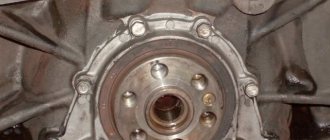
The drive gear is extended to accommodate the other end of the gear into the parking brake compartment at the rear of the transmission housing. There, a brake pulley is mounted on the inside end of the drive gear.
The satellites, located in needle bearings on the carrier axles, are constantly in mesh with the sun gear through its ring gear. On the back of the sun gear there is a flange to which the brake pulley is bolted. When the sun gear brake is released, it, being in the plain bearing, simply rotates freely.
It should be borne in mind that the stopping brakes and sun gear brakes of the DT-75 tractor are of the floating type, which allows braking both when moving forward and backward. They consist of two halves, which are connected by a hinge, so that when replacing the belt, it is not necessary to remove the brake pulleys. The stopping brakes have solid linings and the sun gear brakes have woven asbestos linings.
On the topic “Drive axle of the DT-75 tractor” (I course)
LESSON PLAN
Topic: Drive axle of the DT-75 caterpillar tractor.
Class type: combined.
Method: independent cognitive activity of students.
Goals:
1. Study the structure and operating principle of the drive axle of the DT-75 caterpillar tractor.
2. Develop cognitive interest and the ability for imaginative thinking.
3. Cultivate attentiveness, discipline, perseverance, accuracy.
Equipment: PC, video projector, computer presentation, module 6, study guide.
PROGRESS OF THE CLASS
Organizational moment (2 min).
Repetition of the topic “Clutch of tractors MTZ-80, DT-75).
Presentation of new material (work with an instruction card, story, dialogue, independent work).
Training element - 2
On a crawler tractor, the drive axle, commonly called the rear axle, consists of a final drive, planetary gears, and final drives.
The rear axle mechanisms are housed in a housing divided by partitions into three compartments. In the middle part there are the main gear and gearboxes of the planetary rotation mechanisms, in the other two there are stopping brakes and sun gear brakes. The final drives are made in separate housings.
Training element – 3
main gear
includes a pair of bevel gears. The drive (small) gear is manufactured integrally with the gearbox secondary shaft. The driven (large) main gear is made in the form of a crown and is bolted to the ring gear flange. The latter is a drum with teeth cut inside. Steel shims are installed between the driven gear and the ring gear flange, which regulate the gap between the teeth of the bevel gears. For ease of removal and installation, the gaskets are made in the form of half rings with open grooves inside for mounting bolts.
The ring gear rests on two ball bearings, pressed with outer races into the bores of this gear. The inner races of the bearings are mounted on cups, the flanges of which are bolted to the housing partitions.
Training element - 4
Planetary mechanism
The steering wheel consists of a planetary gearbox and two brakes: a stopping brake and a sun gear brake. Using the planetary mechanism, you can slow down or stop the transmission of rotation to one of the tracks, and the tractor will turn. The planetary gearbox, mounted inside the ring gear, includes a movable housing - the carrier. a, three satellites and a sun gear.
The carrier is a steel casting of two triangular flanges connected by cast bridges. A hub with internal splines is cast to the center of the drive. The splined end of the axle shaft 14 fits into the hub splines, its other end fits into the internal splines of the final drive drive gear. A stopping brake pulley is installed on the outer splined shank of the drive gear, which extends into the brake compartment of the rear axle.
The satellites rotate freely on needle bearings, the teeth of the satellites are in constant mesh with the ring and sun gears. The sun gear is a glass with teeth cut on one end and a flange with threaded holes on the other. The sun gear brake pulley is screwed to the flange. All pulleys are covered by brake bands, which consist of two halves connected by a hinge. With this design of the belts, they can be replaced without removing the brake pulleys.
Planetary mechanisms work as follows: when the tractor moves in a straight line, the sun gear pulleys are completely inhibited by the belts, and the axle pulleys are in a free state. The rotation from the main gear is transmitted to the ring gear, which drives the satellites. Rotating around the axes, the satellites simultaneously roll around the sun gears, dragging the carrier and the associated axle shafts 14, as well as the drive wheels (sprockets) of the tractor into a rotational motion. The rotational speed of the ring gear is reduced by 1.4 times, and the torque increases accordingly.
All brake bands are made of steel, friction linings are riveted to the inner surface of the sun gear brake bands, and a set of pads made of hard friction material is mounted to the stopping brake bands. Each tape in a free state should have the shape of a circle. When the pulleys and belts are free, there should be a gap of 1.5... 1.8 mm. To distribute it evenly, tension springs are used, as well as adjusting screws screwed into the threaded holes of the rear axle housing.
At the upper ends of the brake bands there are adjusting screws, at the ends of which adjusting nuts are screwed. Loops made of strip steel are riveted to the other ends of the strips. The hinges have slots. They include earrings that connect the hinge axes to the fingers of the brackets. The fingers are connected through the earrings to the levers or brakes. The stopping brake lever is connected by rod 8 to the brake pedal, and the sun gear brake lever is connected to the control lever. A tension spring rests against one of the arms of the lever. It tends to turn the sun gear brake levers back counterclockwise (as viewed from the right). The spring force is transmitted through a double-arm lever and earrings to the brake band, which is pressed tightly and with great force against the pulley.
The gears of the planetary mechanisms and the main gear are lubricated with oil, poured into the central compartment of the rear axle to the top mark on the rod fixed in the filler plug. To prevent oil leakage in the brake compartment, sealing devices are provided in the sun gear hubs. Oil that has penetrated the seal in the brake compartment is removed through threaded holes in the lower part of the housing that are closed with plugs.
Training element – 5
- Reinforcement of the studied material in the form of a crossword puzzle.
- Summing up the lesson.
- Grading.
Homework: §12.2, pp. 169-170, control mechanism, textbook “Tractors”, V.A. Rodichev.
Diagram of the rear axle DT-75
| № | Name | Catalog number | Quantity per model |
| Rear axle | 77.38.001 | 1 | |
| Stop Brake Band Assembly (Replacement Parts Only) | 77.38.040 | 2 | |
| Planetary gear kit with satellite axis and needle rollers assembled (for spare parts) | 77.38.055R | 6 | |
| Stop Brake Pulley with Locking Bars Assembly (for spare parts) | 77.38.056R | 2 | |
| Bolt М12Х60, GOST 7795-62 | — | 2 | |
| Bolt М8Х16, GOST 7796-62 | — | 8 | |
| Magnet | 54.38.602 | 1 | |
| Bolt М12Х30, GOST 7796-62 | — | 6 | |
| Bolt М12Х35, GOST 7796-62 | — | 12 | |
| Screw M12X12, GOST 1477-58 | — | 1 | |
| Square nut (non-standard) | GK-M12 | 8 | |
| Rivet 4Х10, GOST 10299-62 | — | 16 | |
| Rivet 6Х14, GOST 10299-62 | — | 4 | |
| Hairpin BM10X28 (16/20), GOST 11765-66 | — | 3 | |
| Cotter pin 2Х12, GOST 397-66 | — | 2 | |
| 1 | Bolt М12Х25, GOST 7796-62 | — | 14 |
| 2 | Spring washer 12N, GOST 6402-61 | — | 34 |
| 3 | Washer | 77.38.198 | 2 |
| 4 | Pad | 77.38.199 | 2 |
| 5 | Rear axle shaft | 77.38.102 | 2 |
| 6 | Stop Brake Pulley | 77.38.146-1 | 2 |
| 7 | Spring washer 10N, GOST 6402-61 | — | 16 |
| 8 | Bolt M10X20, GOST 7796-62 | — | 8 |
| 9 | Pin | A38-89 | 2 |
| 10 | Left control box assembly | 77.38.030-1 | 1 |
| 11 | Planetary brake spring assembly | 77.38.036 | 2 |
| 12 | Spacer sleeve | 77.38.262 | 2 |
| 13 | Planetary brake spring bracket | 77.38.224-1 | 2 |
| 14 | Bracket with planetary brake spring assembly (left) | 77.38.043 | 1 |
| 15 | Upper spring | 77.38.130A | 4 |
| 16 | Rear axle cover gasket | 77.38.223-1 | 1 |
| 17 | Planetary brake pulley | 77.38.145 | 2 |
| 18 | Manhole cover | 77.38.208A | 1 |
| 19 | Manhole cover gasket | 77.38.209 | 1 |
| 20 | Filler plug assembly | 77.38.024-1 | 1 |
| 21 | Plug gasket | 77.38.203 | 1 |
| 22 | Rear axle cover assembly | 77.38.022-2 | 1 |
| 23 | Planetary brake band bracket | 77.38.205 | 2 |
| 24 | Segment key 4Х6.5, GOST 8795-58 | — | 2 |
| 25 | Right planetary brake lever | 77.38.035 | 1 |
| 26 | Cotter pin 4Х22, GOST 397-66 | — | 22 |
| 27 | Right control box assembly | 77.38.031-1 | 1 |
| 28 | Finger | 77.38.228 | 10 |
| 29 | Right parking brake lever | 77.38.033 | 1 |
| 30 | Axis | 77.38.221 | 2 |
| 31 | Control box gasket | 77.38.168-1 | 2 |
| 32 | Double lever finger | 77.38.218 | 4 |
| 33 | Cotter pin 4Х36, GOST 397-66 | — | 8 |
| 34 | Spacer sleeve | 77.38.187 | 4 |
| 35 | Bracket with planetary brake spring assembly (right) | 77.38.044 | 1 |
| 36 | Adjustment screw | 77.38.129 | 4 |
| 37 | Bottom cover | 77.38.127 | 4 |
| 38 | Pad | 77.38.128 | 4 |
| 39 | Planetary mechanism assembly | 77.38.011 | 1 |
| 40 | Plug gasket | 77.37.203 | 1 |
| 41 | Drain plug with magnet assembly | 77.37.019A | 1 |
| 42 | Bolt | 77.38.193 | 3 |
| 43 | Casing assembly | 77.38.028-1 | 1 |
| 44 | Transmission housing | 77.38.101-1A | 1 |
| 45 | Transmission housing assembly with studs | 77.38.021-1A | 1 |
| 46 | Bearing cup gasket | 77.38.222 | 2 |
| 48 | Seal assembly | 77.38.014A | 2 |
| 49 | Bolt М12Х40, GOST 7796-62 | — | 12 |
| 50 | Spring washer 12T, GOST 6402-61 | — | 12 |
| 51 | Ring sealing | 77.38.184 | 2 |
| 52 | Brake band lower branch | 77.38.158-1 | 2 |
| 53 | Lower brake band pad | 77.38.149-1 | 2 |
| 54 | The lower branch of the belt assembly | 77.38.018-1 | 2 |
| 55 | Planetary brake band assembly | 77.38.016-1A | 2 |
| 56 | Pin | 77.38.200 | 4 |
| 57 | Locking plate | 77.38.186-1 | 4 |
| 58 | Finger support | 77.38.125 | 4 |
| 59 | Locking plate | 77.38.138 | 8 |
| 60 | Ring sealing | 77.38.212 | 2 |
| 61 | Bolt М12Х1,25Х30, GOST 7796-62 | — | 12 |
| 62 | Spring bracket axis | 77.38.226-1 | 2 |
| 63 | Screw clamp (non-standard) | HSV-52 | 4 |
| 64 | Case | 77.38.188 | 4 |
| 65 | Sloping hatch cover | 77.38.206 | 2 |
| 66 | Left planetary brake lever | 77.38.034 | 1 |
| 67 | Nut M8, GOST 5915-62 | — | 8 |
| 68 | Spring washer 8N, GOST 6402-61 | — | 8 |
| 69 | Sunroof cover gasket | 77.38.213 | 2 |
| 70 | Left parking brake lever | 77.38.032 | 1 |
| 71 | Stop brake earring | 77.38.219 | 2 |
| 72 | Overlay | 77.38.189-1 | 4 |
| 73 | Lever double-armed short | 77.38.215 | 4 |
| 74 | Spring ring | 54.05.436 | 2 |
| 75 | Finger | 77.38.229 | 4 |
| 76 | Trim gasket | 77.38.147-1 | 4 |
| 77 | Bolt М14Х55, GOST 7795-62 | — | 16 |
| 78 | Spring washer 14T, GOST 6402-61 | — | 16 |
| 79 | Brake bracket pin | 77.38.196 | 4 |
| 80 | Stop Brake Band Bracket | 77.38.204 | 2 |
| 81 | Brake bracket pin | 77.38.217 | 4 |
| 82 | Brake tension nut | 77.38.214 | 4 |
| 83 | Brake adjustment hatch cover assembly | 77.38.029-1 | 4 |
| 84 | Brake band pin | 77.38.181-1 | 4 |
| 85 | Bolt | 77.38.160-1 | 8 |
| 86 | Adjustment screw | 77.38.164-1 | 4 |
| 87 | Nut M10X1.25-050, GOST 5918-62 | — | 8 |
| 88 | Adjustable cotter pin 3.2X18, GOST 397-66 | — | 8 |
| 89 | Eye pin | 77.38.151 | 4 |
| 90 | Earring | 77.38.152 | 8 |
| 91 | Stopping brake band lower branch | 77.38.260 | 2 |
| 93 | The lower branch of the stopping brake band assembly | 77.38.042 | 2 |
| 94 | Stop brake band assembly | 77.38.040A | 2 |
| 95 | Brake band upper branch | 77.38.153-1 | 2 |
| 96 | Upper brake band lining | 77.38.148-1 | 2 |
| 97 | Upper branch of the belt assembly | 77.38.017-1 | 2 |
| 98 | Long double-arm lever | 77.38.216 | 4 |
| 99 | Planetary brake earring | 77.38.220 | 2 |
| 100 | Bolt М10Х25, GOST 7796-62 | — | 8 |
| 101 | Adjustment hatch cover gasket | 77.38.201-1 | 4 |
| 102 | Threaded plug RKII-3/8″, GOST 3112-54 | — | 2 |
| 103 | Nut M12, GOST 5915-62 | — | 4 |
| 104 | Cotter pin 3.2Х25, GOST 397-66 | — | 4 |
| 105 | Brake band pin | 77.38.150 | 4 |
| 106 | Upper brake band | 77.38.259 | 2 |
| 107 | Upper brake band lining | 77.38.257 | 2 |
| 108 | Upper branch of the stopping brake band assembly | 77.38.041 | 2 |
| 110 | Adjustment spacer (0.5 mm) | 77.38.135A | 8 |
| 111 | Adjustment spacer (0.2 mm) | 77.38.134A | 8 |
| 112 | Adjustment spacer (0.1 mm) | 77.38.133A | 4 |
| 119 | Satellite axis | 77.38.122-1 | 6 |
| 120 | Ring | 77.38.123-1 | 12 |
| 122 | Satellite | 77.38.103-2 | 6 |
| 125 | Ring sealing | 77.38.106 | 2 |
| 128 | Retaining ring | 77.38.110A | 2 |
| 134 | Retaining ring | 77.38.137A | 2 |
| 142 | Pipe | 77.38.176 | 2 |
| 143 | Screed | 77.38.177 | 2 |
| 145 | Sleeve | 77.38.211-1 | 2 |
| 148 | Adjustment rod | 77.38.178 | 2 |
| 150 | Oil seal housing | 77.38.117 | 2 |
| 155 | Special washer | 77.38.112 | 2 |
| 159 | Cup | 77.38.116 | 2 |
Components and parts of the rear axle DT-75
| Name | Catalog number | Quantity per model |
| Sun gear assembly | 77.38.012 | |
| Left control box assembly | 77.38.030-1 | 1 |
| Filler plug assembly | 77.38.024-1 | 1 |
| Right planetary brake lever | 77.38.035 | 1 |
| Right control box assembly | 77.38.031-1 | 1 |
| Right parking brake lever | 77.38.033 | 1 |
| Planetary mechanism assembly | 77.38.011 | 1 |
| Casing assembly | 77.38.028-1 | 1 |
| Transmission housing | 77.38.101-1A | 1 |
| Transmission housing assembly with studs | 77.38.021-1A | 1 |
| Seal assembly | 77.38.014A | 2 |
| Planetary brake band assembly | 77.38.016-1A | 2 |
| Left planetary brake lever | 77.38.034 | 1 |
| Left parking brake lever | 77.38.032 | 1 |
| Brake adjustment hatch cover assembly | 77.38.029-1 | 4 |
| Stop brake band assembly | 77.38.040A | 2 |
| Bearing cup | 77.38.141 | 2 |
| Bearing cup assembly | 77.38.023 | 2 |
| Upper plate with bushing assembly | 77.38.026 | 2 |
| Oil seal assembly | 77.38.013-1A | 2 |
| Ring sealing | 77.38.106 | |
| Retaining ring | 77.38.110A | |
| Special washer | 77.38.112 | |
| Cup | 77.38.116 | |
| Oil seal housing | 77.38.117 | |
| Satellite axis | 77.38.122-1 | |
| Ring | 77.38.123-1 | |
| Rear axle shaft | 77.38.102 | 2 |
| Planetary brake spring assembly | 77.38.036 | 2 |
| Finger support | 77.38.125 | 4 |
| Large bevel gear | 77.38.121 | 1 |
| Ring gear | 77.38.108 | 1 |
| Satellite | 77.38.103-2 | 6 |
| Ring | 77.38.118-1 | 2 |
| Stub | 77.38.109 | 2 |
| Ring sealing | 77.38.113 | 2 |
| Carrier | 77.38.105-1 | 2 |
| Carrier with satellites assembled | 77.38.037 | 2 |
| Sun gear | 77.38.104 | 2 |
| Ring sealing | 77.38.107 | 2 |
| Ring | 77.38.119-1 | 2 |
| Thrust washer | 77.38.111 | 2 |
| Spring | 77.38.115 | 2 |
| Retaining ring | 77.38.114 | 2 |
| Pad | 77.38.128 | |
| Adjustment screw | 77.38.129 | |
| Adjustment spacer (0.1 mm) | 77.38.133A | |
| Adjustment spacer (0.2 mm) | 77.38.134A | |
| Adjustment spacer (0.5 mm) | 77.38.135A | |
| Retaining ring | 77.38.137A | |
| Rivet | 77.38.140-1 | |
| Stop Brake Pulley | 77.38.146-1 | |
| Eye pin | 77.38.151 | |
| Earring | 77.38.152 | |
| Adjustment screw | 77.38.164-1 | |
| Bottom stop brake band lining | 77.38.258 | |
| Upper spring | 77.38.130A | 4 |
| Planetary brake pulley | 77.38.145 | 2 |
| Bottom cover | 77.38.127 | 4 |
| Lower brake band pad | 77.38.149-1 | 2 |
| Locking plate | 77.38.138 | 8 |
| Trim gasket | 77.38.147-1 | 4 |
| Bolt | 77.38.160-1 | 8 |
| Upper brake band lining | 77.38.148-1 | 2 |
| Brake band pin | 77.38.150 | 4 |
| Upper brake band lining | 77.38.257 | 2 |
| Lock washer | 77.38.143A | 4 |
| Locking plate | 77.38.132 | 9 |
| Spacer ring | 77.38.139 | 2 |
| glass ring | 77.38.124 | 2 |
| Ring | 77.38.136 | 2 |
| Bearing sleeve | 77.38.131 | 4 |
| Pipe | 77.38.176 | |
| Screed | 77.38.177 | |
| Adjustment rod | 77.38.178 | |
| Locking plate | 77.38.186-1 | |
| Spacer sleeve | 77.38.187 | |
| Overlay | 77.38.189-1 | |
| Pad | 77.38.199 | |
| Pin | 77.38.200 | |
| Washer | 77.38.198 | 2 |
| Plug gasket | 77.38.203 | 1 |
| Planetary brake band bracket | 77.38.205 | 2 |
| Control box gasket | 77.38.168-1 | 2 |
| Ring sealing | 77.38.184 | 2 |
| Case | 77.38.188 | 4 |
| Sloping hatch cover | 77.38.206 | 2 |
| Brake bracket pin | 77.38.196 | 4 |
| Stop Brake Band Bracket | 77.38.204 | 2 |
| Brake band pin | 77.38.181-1 | 4 |
| Adjustment hatch cover gasket | 77.38.201-1 | 4 |
| Rivet | 77.38.140-1 | 6 |
| External spring | 77.38.174A | 2 |
| Spring internal | 77.38.175 | 2 |
| Cork | 77.37.202A | 1 |
| Manhole cover gasket | 77.38.209 | |
| Sleeve | 77.38.211-1 | |
| Brake tension nut | 77.38.214 | |
| Lever double-armed short | 77.38.215 | |
| Long double-arm lever | 77.38.216 | |
| Brake bracket pin | 77.38.217 | |
| Planetary brake earring | 77.38.220 | |
| Bearing cup gasket | 77.38.222 | |
| Planetary brake spring bracket | 77.38.224-1 | |
| Sleeve | 77.38.231 | 8 |
| Small pin | 77.38.705 | 4 |
| Large pin | 77.38.706 | 4 |
| Spacer sleeve | 77.38.262 | 2 |
| Rear axle cover gasket | 77.38.223-1 | 1 |
| Manhole cover | 77.38.208A | 1 |
| Finger | 77.38.228 | 10 |
| Axis | 77.38.221 | 2 |
| Double lever finger | 77.38.218 | 4 |
| Ring sealing | 77.38.212 | 2 |
| Spring bracket axis | 77.38.226-1 | 2 |
| Sunroof cover gasket | 77.38.213 | 2 |
| Stop brake earring | 77.38.219 | 2 |
| Finger | 77.38.229 | 4 |
| Bottom stop brake band lining | 77.38.258 | 2 |
| Bottom plate | 77.38.235 | 2 |
| Top plate | 77.38.210 | 2 |
| Eye | 77.38.236 | 2 |
| Spring | 77.38.237 | 2 |
| Washer | 77.38.261 | 2 |
We offer the rear axle of the DT-75 tractor in a fully assembled version directly from the manufacturer, which provides double benefits. Firstly, the DT-75 rear axle will cost less than from intermediaries. Secondly, you can buy a DT-75 rear axle with a guarantee from the manufacturer.
Rating: 4.6/5 — 16 votes
Tractor DT-75
Introduction 1 Description of the tractor 2 Purpose 3 Equipment and production 4 Technical characteristics 5 Tractor DT-75 with bulldozer equipment Conclusion Bibliography
INTRODUCTION
DT-75 (75M,RV,N,D,E) is a general-purpose tracked agricultural tractor. The most popular caterpillar tractor in the USSR. In 2008, the Volgograd Tractor Plant celebrated the 45th anniversary of the launch of the DT-75. The tractor has gained a good reputation due to its successful combination of good performance properties (simplicity, efficiency, maintainability) and low cost compared to other tractors of a similar class. Over such a long period of time, the DT-75 was modernized several times: it was modified externally and internally, usually for the better. As of 2009, more than 2,741,000 units of tractors were manufactured. In August 2009, another modernization of the tractor rolled off the plant assembly line. The restyled tractor is equipped with a new cabin and a plastic hood, a new economical and environmentally friendly Finnish Sisu engine, the production of which was launched at the Vladimir Tractor and Motor Plant. It has a new index VT-90V (Trade name “Agromash 90 TG”). The signature color of the tractor has changed from red to blue-gray with orange color inserts. The production of the previous obsolete design DT-75DE is still ongoing. An industrial modification of the DT-75 tractor is the T-90 tractor, which differs from the base model in the presence of support hinges for hanging the front blade and front hydraulic cylinders for controlling it. In addition, the T-90 has different transmission ratios.