To check, you will need a multimeter, a car battery and a lamp with soldered wires, wires for connecting between the generator and the battery, and you can also take a drill with a suitable head, since you may have to twist the rotor by the nut on the pulley.
Alternator This causes significant current to flow through the valves and damages them.
But, if for some reason there is no new one or there is no money to purchase it, and your hands grow where necessary, then you can install an external voltage regulator, for example a regulator Replacing a VAZ 2101 generator with a VAZ 2109 generator (Excitation connection diagram)
To repair the bearing assembly of this generator, you can attract specialists with less qualifications.
Let's see what the Russian market offers us to replace a failed generator, and at the same time test the proposed models in our testing laboratory.
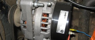
I initially assumed that the startvolt was larger, but in fact it turned out to be almost more compact: Before installing the generator, I leveled the seats with a file and degreased them: After that, you can tighten them: The tightened terminals - both plus and minus are covered with a magic elixir: Instead of a bolt for adjusting the belt tension I also screwed in the pan pin.
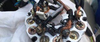
If such symptoms occur, the separator elements, raceways, and slip rings should be checked for rotation. I know how to solder and love it, but I hope that I won’t have to: The rectifier plates are quite thick: The aluminum casting of the housing is of excellent quality, the generator is pleasant to hold in your hands: From a different angle: The front cooling impeller: The “pill” terminals of the relay-regulator are connected to the brush assembly soldering: The “tablet” itself does not have any markings.
Assessing the reviews of motorists, we can say with confidence: this generator is a variant of the classic reliable design without pretensions to outstanding performance, but guaranteeing trouble-free operation. Rectifier block.
Generator Startvolt LG 0101 for VAZ 2101 100A - yellow penny - Part 2
kvarius › Blog › one of the battery charging schemes
Diagram of the G-221 generator system (the voltage regulator RR-380 of the electromagnetic type is shown):
1 - generator rotor winding; 2 - generator; 3 — generator stator winding; 4 — generator rectifier; 5 - battery; 6 — ignition switch; 7 — battery charge indicator lamp; 8 — battery charge warning lamp relay; 9 — fuse block; 10 - throttle; 11 — thermal compensating resistor; 12 — additional resistors; 13 - voltage regulator.
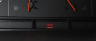
Regulator 13 maintains the generator voltage at 13.2–14.5. The serviceability of the generator is checked using test lamp 7 in the instrument cluster and relay 8.
When the ignition is turned on, when the engine (and therefore the generator) is not yet running, current from the battery flows through the relay contacts and the lamp lights up. After starting the engine and when the car is moving, the lamp should go out, since under the action of the rectified phase voltage of the generator, the relay armature should be attracted to the core and open the relay contacts.
Battery and generator
These are the two main sources of current in a car. Many people have heard about them, but not everyone knows the features and working conditions of the latter. Many of us have Soviet-made cars and, apparently, many of us have encountered the problem of the engine failing to start when the battery charge level is low (battery, of course), especially in winter. Let's take a little look at these electrical appliances. Each of us has a rechargeable battery in our car (in the future I will say either a battery or a battery so that the buttons on the keyboard wear out less). And many of us know that when the engine is not running, all devices run on battery power. No one will argue with this.
Simple methods and diagrams for connecting a car generator
The main source of electrical energy in any vehicle is the generator. Thanks to this unit, all electrical equipment of the car is powered, so it should always be operational. What is the generator connection diagram, what is its structure and principle of operation, and how to diagnose the unit? We will talk about this below.
What are the requirements for a car generator?
The main user requirement for a car generator is the simultaneous supply of electrical energy to consumers and charging of the battery, the inclusion of regular consumers of electrical energy without severely discharging the battery and the presence of loads with rotary frequency rotations in the electrical network.
Uninterrupted power supply as a basic requirement
Design and principle of operation
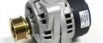
As you know, the main purpose of a generator device is to convert mechanical energy into electrical energy. Thanks to this, the unit restores the capacity of the battery and also allows you to power all electrical equipment in the car. The generator device is located in the front of the power unit and is driven by the crankshaft.
More details about the main elements and principle of operation:
- Rotary mechanism. This element is a shaft with an installed field winding. Both halves of a given winding are located in opposite pole halves of the assembly. The rotor mechanism is driven by a belt drive.
- Slip rings are used to power the winding.
- Stator mechanism - consists of a winding and a core. This element is designed to generate alternating current. The current generated by the mechanism is fed through the rings further along the electrical circuit.
- In order for the generated excitation current to successfully reach the rings, brushes are used. These elements, as practice shows, often fail due to wear and tear.
- Rectifier block. This component is designed to convert AC voltage. Structurally, this device consists of plates with installed diode elements. Depending on the pinout of the unit, the connection diagram for a car generator device may include a separate pair of winding diodes. In this case, voltage will not be able to pass through the battery when the engine is turned off.
- Regulator relay. This element is designed to maintain a certain voltage level in the on-board network within normal limits. The regulator relay directly affects the frequency as well as the duration of the current signals. The regulator itself structurally includes controllers, as well as executive components. Their purpose is to determine the time during which the winding must be connected to the network. If the regulator relay for some reason fails, stabilization of the incoming voltage to the battery is lost.
- The body of the device in which the main parts and components of the unit are located. The body itself is usually made of aluminum, so its weight is relatively light. The installation housing allows heat to be quickly dissipated, as a result of which the temperature does not reach a critical level. Also, the case is non-magnetic (the author of the video about the operating principle of the device is Mikhail Nesterov).
Voltage regulator
Voltage regulator is a device that maintains the voltage of the on-board electrical network within a given limit in all operating modes. The voltage is maintained by it if the frequency of the rotor generator rotation, electrical load and air temperature changes. It performs the function of protecting generator elements from accidents and automatically connecting the excitation winding circuit with an alarm system to the on-board network. Checked with a test lamp.
There are combined and separate voltage regulators. The first type has a combined regulator design with an alkaline housing assembly. The second type is a separate unit of the car body, the engine compartment, where the generator wires fit and are pulled.
You may be interested in A number of circuit breakers
Voltage regulator
Checking a faulty generator
Let's consider the main malfunctions typical of automobile generator sets:
- Open circuit, short circuit and other damage. To diagnose such a malfunction, you need to check the number of amperes, as well as the voltage level at the output of the device. In accordance with the data obtained, a solution to this problem is selected.
- Often our compatriots are faced with such a problem as wear of graphite brushes, voltage regulator, and diode bridge. All worn out and failed elements can be repaired, but usually they are replaced. Separately, it should be said about the regulator - as mentioned above, it ensures optimal battery charge in accordance with the temperature in the engine compartment. Thus, the device automatically detects the number of volts for the battery under current conditions. Depending on the model of the generating set, a regulator with manual switching may be used in accordance with the time of year; in this case, sub-zero temperatures will not be harmful to the device. A broken relay can be indicated by unstable voltage in the system - for example, dim headlights that become brighter when you press the gas pedal.
- Bearing failure. Failure of these elements can be indicated by increased noise, but the same sign also indicates insufficient lubrication.
- Shui and howl. If such symptoms occur, the separator elements, raceways, and slip rings should be checked for rotation. Also, such a symptom may indicate a possible interturn short circuit in the windings of the stator mechanism or traction relay. In principle, when third-party sounds appear, you should also diagnose the state of the contacts.
- The temperature of a working generator set can be up to 90 degrees, but if there is obvious overheating, the diode bridge should be diagnosed. You also need to make sure that there are not many additional devices and devices connected to the vehicle’s on-board network. When the temperature rises critically, the insulation winding of the stator mechanism will first darken; moreover, it may melt.
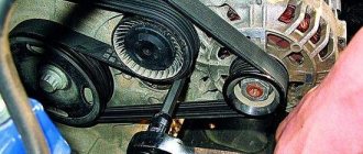
- Worn generator set belt. If the alternator belt wears out and breaks, this will lead to incorrect operation of the unit as a whole, that is, all energy consumers in the car will be powered by the battery. If the belt breaks, the generator stops functioning, so the driver only has time to get to the nearest service station or garage to fix the problem. Voltage surges in the vehicle’s on-board network can indicate wear and tear. It is necessary to check the integrity of the strap and pay attention to its condition - cracks and other types of damage to the strap are not allowed. If they are present, then you need to understand that the belt will have to be changed soon.
What to do if the generator is faulty
The main cause of generator malfunction is wear with damage to the pulley, wear of the current collection brushes, damage to the slip wheels, wear of the voltage regulator, short circuit of the stator winding turns, wear or destruction of the bearing, damage to the rectifier or diode bridge and damage to the charging circuit conductor.
Malfunctions are associated with malfunction of the housing with bearings, pressure springs, belt wire, burnout and wear of brushes, interturn short circuits, breakdowns, rotor runouts and malfunctions of the control relay.
It is recommended to repair a faulty generator yourself only if you have special equipment and knowledge of how to operate the installation. All the user can do is visually assess the condition of the equipment and check it with a multimeter or other tester if the breakdown is associated with a short circuit or open circuit.
Note! In the event of another malfunction, you must contact a professional service, which has a long history of dismantling, disassembling the unit and eliminating existing faults. Only in this case can you quickly and efficiently repair a faulty generator.
You may be interested in Power supply for 12 V halogen lamps
Professional repair of electric generator
In general, a generator is an electromechanical equipment that produces or produces electrical, mechanical, chemical and thermal energy and then converts it into another. It has a different design and diagram, according to which you can learn how to connect the equipment yourself. In case of malfunction, professional service is required.
Car generator circuit
1200 rub. for the photo report
We pay for photo reports on car repairs. Earnings from 10,000 rubles/month.
Write:
The most basic function of the generator is to charge the battery and power the electrical equipment of the engine.
A generator is a mechanism that converts mechanical energy into electrical energy. The generator has a shaft on which a pulley is mounted, through which it receives rotation from the engine crankshaft.
Interactive image of the generator circuit. Works on mouseover
A car generator is used to power electrical consumers, such as the ignition system, on-board computer, car lighting, diagnostic system, and it is also possible to charge a car battery. The power of a passenger car generator is approximately 1 kW. Car generators are quite reliable in operation because they ensure uninterrupted operation of many devices in the car, and therefore the requirements for them are appropriate.
Technical characteristics of the VAZ 2108 generator
The following generator models are installed on VAZ 2108 cars:
- 3701
- 3701
Technical characteristics of the first:
- The value of the delivered current (at 6000 rpm-1 and a voltage of 13 V) – 55 A — The voltage value – 13.6 – 14.6 V
- Rotor rotation direction – right – Maximum rotor speed – 13000 rpm-1
- Engine/generator gear ratio 1/2.04
Technical characteristics of the second:
- The value of the delivered current (at 6000 rpm-1 and a voltage of 13 V) – 80 A — The voltage value – 13.2 – 14.7 V
- Rotor rotation direction: right
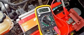
A normally working, serviceable generator of VAZ 2108, 2109, 21099 cars and their modifications produces a voltage in the range of 13.6 V - 14.6 V. This can be visually tracked using a voltmeter on the instrument panel, but it is better to measure the voltage with a voltmeter (multimeter, autotester
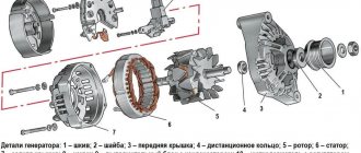
Generator device
The design of a car generator implies the presence of its own rectifier and control circuit. The generating part of the generator, using a stationary winding (stator), generates three-phase alternating current, which is then rectified by a series of six large diodes and the direct current charges the battery. Alternating current is induced by the rotating magnetic field of the winding (around the field winding or rotor). Next, the current is supplied to the electronic circuit through the brushes and slip rings.
Charging a car battery from a generator
Since during operation the battery goes through many charge-discharge cycles, receiving energy from the car generator and distributing it as needed to consumers, for example, powering the radio, headlights, heated glass, climate control and other equipment, various problems often arise in the operation of the system. As a result, the battery is either undercharged or, on the contrary, overcharged. Let's look at the dangers of both phenomena.
When overcharging, overheating, oxidation and rapid shedding of the positive plates occur, and water boils away from the electrolyte. It should be noted that batteries with antimony lead plates most often boil. More modern and expensive batteries with calcium plates are practically not subject to overcharging, since when the limit value is reached they stop charging on their own. In addition, when overcharged, the plates shed, and residual sludge, accumulating at the bottom, can subsequently cause the battery to short out.
If undercharged, there is a high probability that the battery will completely die, dropping the charge level below a critical value, after which the battery can no longer be restored. In addition, when the density of the electrolyte drops, there is a risk of the cans freezing, which may result in the destruction of the plates.
In order to prevent such phenomena, all cars are equipped with special relay regulators that control the battery charge.
Often, car owners complain that, and, as a result, it constantly works in an unfavorable mode, and therefore its service life is significantly reduced. Before you start charging a car battery, it is necessary to establish the reasons that caused its discharge, since when the battery is functioning normally, there is, as a rule, no need to resort to the use of autonomous chargers.
Generator connection diagram for VAZ 2107
The VAZ 2107 charging scheme depends on what type of generator is used. To recharge the battery on cars such as VAZ-2107, VAZ-2104, VAZ-2105, which have a carburetor engine, you will need a G-222 type generator or its equivalent with a maximum output current of 55A. In turn, VAZ-2107 cars with an injection engine use a generator 5142.3771 or its prototype, which is called a high-energy generator, with a maximum output current of 80-90A. It is also possible to install more powerful generators with an output current of up to 100A. Absolutely all types of alternating current generators have built-in rectifier units and voltage regulators; they are usually made in the same housing with brushes or are removable and mounted on the housing itself.
The VAZ 2107 charging circuit has minor differences depending on the year of manufacture of the car. The most important difference is the presence or absence of a charge indicator lamp, which is located on the instrument panel, as well as the method of connecting it and the presence or absence of a voltmeter. Such circuits are mainly used on carburetor cars, while on cars with injection engines the circuit does not change, it is identical to those cars that were manufactured previously.
Generator set designations:
- “Plus” of the power rectifier: “+”, V, 30, V+, WAT.
- “Ground”: “-”, D-, 31, B-, M, E, GRD.
- Excitation winding output: Ш, 67, DF, F, EXC, E, FLD.
- Output for connection to the serviceability lamp: D, D+, 61, L, WL, IND.
- Phase output:
,W,R,STA.
- Output of the stator winding zero point: 0, MP.
- Output of the voltage regulator for connecting it to the on-board network, usually to the “+” of the battery: B, 15, S.
- Voltage regulator output for powering it from the ignition switch: IG.
- Voltage regulator output for connecting it to the on-board computer: FR, F.
Generator circuit VAZ-2107 type 37.3701
- Accumulator battery.
- Generator.
- Voltage regulator.
- Mounting block.
- Ignition switch.
- Voltmeter.
- Battery charge indicator lamp.
When the ignition is turned on, the plus from the lock goes to fuse No. 10, and then goes to the battery charge indicator lamp relay, then goes to the contact and to the coil output. The second terminal of the coil interacts with the central terminal of the starter, where all three windings are connected. If the relay contacts close, then the control lamp lights up. When the engine starts, the generator generates current and an alternating voltage of 7V appears on the windings. Current passes through the relay coil and the armature begins to attract, and the contacts open. Generator No. 15 passes current through fuse No. 9. Similarly, the excitation winding receives power through the brush voltage generator.
Malfunctions of autogenerators and ways to eliminate them
When operating generators, mechanical and electrical faults may occur. Often, one failure that is not corrected in time becomes the cause of others.
Signs of generator damage:
- flashing or constant operation of the charging lamp when the engine is running;
- insufficient charging or overcharging of the battery;
- dim light of external light alarm;
- lamp pulsations;
- a significant increase in the brightness of the lamps with increasing speed;
- extraneous sounds, the source of which is the generator or drive.
Mechanical breakdowns
Common mechanical faults:
- the appearance of cracks on the drive pulley;
- drive belt break;
- wear of the armature bearings, which leads to jamming of the generator.
Cracks and chips on the pulley are detected during a visual inspection of the unit. The sharp edges begin to destroy the drive belt, which can come off the pulley along the damaged edges. A broken or burst pulley must be replaced with a new one; repair of the unit is impossible. The new pulley must have the same geometric parameters as the worn one.
Damaged armature bearings begin to emit a characteristic whistle during operation. You should not delay repairs, since the operating mode of the generator is disrupted due to a change in the gap between the armature and the stator. As a result, the armature may jam, which will lead to belt breakage and damage to the brushes and windings.
Electrical breakdowns
Failures of the electrical part of generators:
- abrasion of current collecting brushes;
- wiping the commutator part of the generator rotor;
- failure of the voltage regulator;
- interturn short circuits of the stator winding;
- burnout of the rectifier diode bridge;
- destruction of connecting wiring;
- burning or oxidation of wiring connections.
To check the functionality of the generator, use a multimeter or voltmeter designed to measure a direct voltage of 0-20 V. Before starting measurements, it is recommended to warm up the unit by letting it run for 10-15 minutes with the engine idling and the consumer running (for example, low beam headlights). Measuring the voltage between the positive terminal of the generator and the vehicle ground should show a value in the range of 13.5-14.5 V. More accurate information is available in the repair and maintenance instructions for the car. If the voltage deviates from the standard, the relay regulator must be replaced.
Checking the voltage at the battery terminals allows you to detect damage to the connecting wiring. For a full measurement, it is necessary to increase the engine speed to high and connect powerful energy consumers (for example, high beam headlights, heated windows and seats). In this case, the voltage should be close to the value on the relay regulator. Otherwise, it is necessary to check the wires and connection points.
The serviceability of the diode bridge is checked by installing a multimeter on the positive terminal of the generator and ground in AC measurement mode. The voltage value should be within 0.5 V. A higher voltage is a sign of a faulty diode bridge.
The process of replacing the generator on a Ford Focus 2 is shown in a video provided by the ABC Ford channel.
Measuring breakdowns of the generator windings is carried out with the battery disconnected and the wiring disconnected from the positive terminal of the device. The tester, switched to ammeter mode, is connected between the terminal and the wiring. A value of up to 0.5 mA is considered acceptable. With increased current, breakdown of parts of the diode bridge or windings is possible.
To check the field windings, it is necessary to remove the generator from the car. Work is being carried out with a remote voltage regulator and brush assembly. Before starting the test, the slip rings are cleaned of dirt. Testing is performed with a multimeter set to ohmmeter mode. The connection is made to slip rings. The normal resistance value is in the range of 5-10 ohms. To measure the breakdown to ground, an ohmmeter is attached to the rings and body. In good condition, the resistance value will be infinite; with other values, there is a breakdown.
It is strictly forbidden to check the operation of generators using the short circuit method. Such actions lead to failure of not only the unit, but also the electronic components. It is recommended to carry out diagnostics of the device on stands available in specialized centers. Doing it yourself can result in costly repairs.
Charging diagram for VAZ with injection engines
This scheme is identical to the schemes on other VAZ models. It differs from the previous ones in the method of exciting and monitoring the serviceability of the generator. It can be carried out using a special control lamp and a voltmeter on the instrument panel. Also, through the charge lamp, the generator is initially excited at the moment it starts working. During operation, the generator operates “anonymously,” that is, excitation comes directly from pin 30. When the ignition is turned on, power through fuse No. 10 goes to the charging lamp in the instrument panel. Then it goes through the mounting block to pin 61. Three additional diodes provide power to the voltage regulator, which in turn transmits it to the excitation winding of the generator. In this case, the indicator lamp will light up. It is at that moment when the generator operates on the plates of the rectifier bridge that the voltage will be much higher than that of the battery. In this case, the control lamp will not light up, because the voltage on its side on the additional diodes will be lower than on the side of the stator winding and the diodes will close. If the control lamp lights up while the generator is running, this may mean that additional diodes are broken.
Regulator relay diagnostics
Voltage regulator failures can be determined by indirect signs. First of all, this is incorrect battery charging:
- overcharge - the electrolyte boils away, the acid solution gets on the body parts
- undercharging - the internal combustion engine does not start, the lamps are dimly lit
However, it is preferable to diagnose with instruments - a voltmeter or tester. Any deviation from the maximum voltage value of 14.5 V (in some cars the on-board network is designed for 14.8 V) at high speeds or the minimum value of 12.8 V at low speeds becomes the reason for replacing/repairing the regulator relay.
Built-in
Most often, the voltage regulator is integrated into the generator brushes, so a level inspection of this unit is necessary:
- After removing the protective cover and loosening the screws, the brush assembly is removed out
- When the brushes are worn out (less than 5 mm of their length remains), replacement must be carried out without fail.
- Generator diagnostics with a multimeter are carried out complete with a battery or charger
- The “negative” wire from the current source is closed to the corresponding regulator plate
- The “positive” wire from the charger or battery is connected to a similar relay connector
- the tester is set to voltmeter mode 0 - 20 V, the probes are placed on the brushes
- in the range of 12.8 - 14.5 V there should be voltage between the brushes
- when the voltage increases above 14.5 V, the voltmeter needle should be at zero
Rice. 22 Diagnostics of the built-in relay
In this case, instead of a voltmeter, you can use a lamp, which should light in the specified voltage range and go out when this characteristic increases above this value.
The wire that controls the tachometer (marked W only on relays for diesel engines) is tested with a multimeter in tester mode. It should have a resistance of about 10 ohms. If this value decreases, the wire is “broken” and should be replaced with a new one.
Remote
There are no differences in diagnostics for the remote relay, but it does not need to be removed from the generator housing. You can check the generator voltage regulator relay with the engine running, changing the speed from low to medium, then high. Simultaneously with the increase in speed, you need to turn on the high beams (at a minimum), the air conditioner, the monitor and other consumers (at a maximum).
Rice. 23 Diagnostics of remote voltage regulator
Thus, if necessary, the vehicle owner can replace the standard voltage regulator relay with a more modern modification of a built-in or remote type. Diagnostics of performance is available on your own with a regular car lamp.
If you have any questions, leave them in the comments below the article. We or our visitors will be happy to answer them
Checking generator operation
You can check the functionality of the generator in several ways using certain methods, for example: you can check the output current of the generator, the voltage drop on the wire that connects the current output of the generator to the battery, or check the regulated voltage.
To check, you will need a multimeter, a car battery and a lamp with soldered wires, wires for connecting between the generator and the battery, and you can also take a drill with a suitable head, since you may have to twist the rotor by the nut on the pulley.
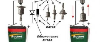
Checking the generator diode bridge
To check the condition of the generator diode bridge, you need to switch the multimeter to AC measurement mode. Connect one test probe of the diagnostic tool to output “B+” (“30”), and the second to ground. The voltage when connecting the probes in this way should be no more than 0.5 Volts. If the voltage is higher, the diodes have probably shorted. You can also check the diodes for breakdown. To do this, disconnect the battery from the generator and also disconnect the wire that goes to the “B+” (“30”) terminal. Next, the multimeter is connected between the disconnected generator wire and “B+” (“30”), after which readings are taken. If the discharge current of the multimeter shows more than 0.5 mA, there is a high probability of breakdown of the diodes.