Checking the VAZ 2107 generator
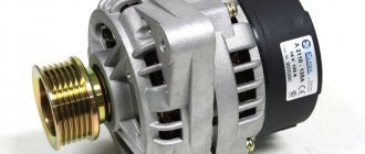
The “seven” generator produces electric current when the engine is running. If problems arise with it, searching for the causes and eliminating the breakdowns must be done immediately. There can be many problems with a generator. Therefore, possible malfunctions need to be dealt with in more detail.
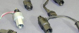
Checking the diode bridge
The diode bridge of the generator consists of several rectifier diodes, which receive an alternating voltage and output a constant voltage. The performance of the generator itself directly depends on the serviceability of these elements. Sometimes diodes fail and need to be checked and replaced. Diagnostics is carried out using a multimeter or a 12 V car light bulb.
Multimeter
The procedure consists of the following steps:
- We check each diode separately, connecting the probes of the device in one position, and then changing the polarity. In one direction the multimeter should show infinite resistance, and in the other - 500-700 ohms.
A light bulb
If you don’t have a multimeter at hand, you can use a regular 12 V light bulb:
- We connect the negative terminal of the battery to the body of the diode bridge. We connect the lamp into the gap between the positive terminal of the battery and the terminal of the generator marked “30”. If the lamp lights up, the diode bridge is faulty.
- To check the negative diodes of the rectifier, we connect the minus of the power supply in the same way as in the previous paragraph, and the plus - through a light bulb with a bolt securing the diode bridge. A burning or flickering lamp indicates problems with the diodes.
- To check the positive elements, plus the batteries, we connect through a lamp to contact “30” of the generator. We connect the negative terminal to the bolt. If the lamp does not light up, the rectifier is considered working.
- To diagnose additional diodes, the minus of the battery remains in the same place as in the previous paragraph, and the plus is connected through a lamp to contact “61” of the generator . A glowing lamp indicates problems with the diodes.
Video: diagnosing the rectifier unit with a light bulb
My father, like many other owners of domestic automobile industry products, used to repair the generator rectifier unit with his own hands. Then the necessary diodes could be obtained without problems. Nowadays, parts for repairing a rectifier are not so easy to find. Therefore, if the diode bridge breaks down, it is replaced with a new one, especially since this is much easier to do than to repair it.
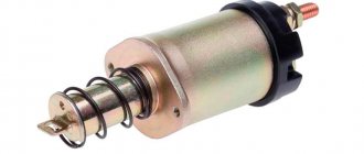
Checking the relay regulator
Since different voltage regulators were installed on VAZ Sevens, it is worth checking each of them in more detail.
Combined relay
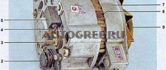
The combined relay is integral with the brushes and is mounted on the generator. You can remove it without dismantling the latter, although this will not be easy. You need to get to the back of the generator, unscrew the two screws securing the relay and remove it from the special hole.
To check the voltage regulator you will need:
- power supply with variable voltage 12–22 V;
- connecting wire;
- 12 V light bulb.
The process itself consists of the following steps:
- We connect the negative of the battery to the ground of the relay, and the positive to its contact “B”. We connect a light bulb to the brushes. We do not include the power source in the circuit yet. The light should light up, and the voltage should be about 12.7 V.
- We connect the power supply to the battery terminals, observing the polarity, and increase the voltage to 14.5 V. The light should go out. When the voltage drops, it should light up again. If this is not the case, the relay must be replaced.
- We continue to increase the tension. If it reaches 15–16 V, and the light continues to light, this will indicate that the relay regulator does not limit the voltage supplied to the battery. The part is considered non-working; it recharges the battery.
Separate relay
A separate relay is mounted on the car body, and the voltage from the generator first goes to it, and then to the battery. As an example, let's look at checking the Ya112B relay, which was also installed on classic Zhiguli cars . Depending on the version, such a regulator can be mounted both on the body and on the generator itself. We dismantle the part and perform the following steps:
- We assemble a circuit similar to the previous one; instead of brushes, we connect a light bulb to contacts “W” and “B” of the relay.
- We perform the check in the same way as in the method described above. The relay is also considered faulty if the lamp continues to light when the voltage increases.
Old type relay
Such a regulator was installed on the old “classic”. The device was mounted on the body; testing it has some differences from the described options. The regulator has two outputs - “67” and “15”. The first is connected to the negative terminal of the battery, and the second to the positive terminal. The light bulb is connected between ground and pin “67”. The sequence of voltage changes and the lamp's reaction to it are the same.
Once, when replacing a voltage regulator, I encountered a situation where, after purchasing and installing a new device, the device showed more than 15 V at the battery terminals instead of the required 14.2–14.5 V. The new relay regulator turned out to be simply faulty. This suggests that it is not always possible to be completely confident in the performance of a new part. When working with electricians, I always control the necessary parameters using the device. If problems arise with charging the battery (overcharging or undercharging), then I start troubleshooting with the voltage regulator. This is the most inexpensive part of the generator, which directly determines how the battery will be charged. That’s why I always carry a spare relay-regulator with me, since a malfunction can occur at the most inopportune moment, and you can’t travel very far without a battery charge.
Read also: Dovetail template for router
Video: checking the generator relay regulator on a “classic”
Capacitor check
The capacitor is used in the voltage regulator circuit as a suppressor of high-frequency interference. The part is attached directly to the generator housing. Sometimes it can fail.
The serviceability of this element is checked using a special device. However, you can get by with a digital multimeter by selecting a measurement limit of 1 MOhm:
- We connect the probes of the device to the terminals of the capacitor. If the element is in good working order, the resistance will be small at first, after which it will begin to increase to infinity.
- We change the polarity. The device readings should be similar. If the capacitance is broken, then the resistance will be small.
If a part fails, it is easy to replace it. To do this, simply unscrew the fastening element holding the container and fixing the wire.
Video: how to check a car alternator capacitor
Checking brushes and slip rings
To check the slip rings on the rotor, the generator will need to be partially disassembled by removing the rear section. Diagnostics consists of visually inspecting the contacts for flaws and wear. The minimum diameter of the rings must be 12.8 mm. Otherwise, the anchor must be replaced. In addition, it is recommended to clean the contacts with fine-grained sandpaper.
The brushes are also inspected, and if they are severely worn out or damaged, they are replaced. The height of the brushes must be at least 4.5 mm. They should move freely and without jamming in their seats.
Video: checking the generator brush assembly
Checking the windings
The "seven" generator has two windings - rotor and stator. The first is fixed to the anchor and constantly rotates when the engine is running, the second is fixedly fixed on the body of the generator itself. Windings sometimes fail. To identify a malfunction, you need to know the testing procedure.
Rotor winding
To diagnose the rotor winding, you will need a multimeter, and the process itself consists of the following steps:
- We measure the resistance between the slip rings. Readings should be between 2.3 and 5.1 ohms. Higher values will indicate poor contact between the winding terminals and the rings. Low resistance indicates a short circuit between the turns. In both cases, the anchor requires repair or replacement.
Stator winding
A break or short circuit may occur with the stator winding. Diagnostics can also be carried out using a multimeter or a 12 V light bulb:
- On the device, select the resistance measurement mode and one by one connect the probes to the terminals of the windings. If there is no break, the resistance should be within 10 ohms. Otherwise it will be infinitely large.
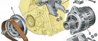
Checking the belt
The generator is driven by a belt from the engine crankshaft pulley. It is necessary to periodically check the belt tension, since if it is loosened, problems with charging the battery may occur. It is also worth paying attention to the integrity of the belt material. If there are visible peels, tears or other damage, the element needs to be replaced. To check its tension, follow these steps:
- We press on one of the belt branches, for example, with a screwdriver, while simultaneously measuring the deflection with a ruler.
Before a long trip, I always inspect the alternator belt. Even if the product is not damaged externally, I keep a belt in stock along with the voltage regulator, because anything can happen on the road. Once I was faced with a situation where the belt broke and two problems arose at the same time: the battery was not charged and the pump was not working because the pump did not rotate. A spare belt helped.
Bearing check
To ensure that a generator malfunction caused by jammed bearings does not take you by surprise, you need to check them when a characteristic noise appears. To do this, the generator will need to be removed from the car and disassembled. We carry out diagnostics in this order:
- We visually inspect the bearings, trying to identify damage to the race, balls, cage, and traces of corrosion.
When checking, you should also pay attention to the front cover of the generator. There should be no cracks or other damage on it. If damage is detected, the part is replaced with a new one.
Checking the combined relay-regulator
Checking the VAZ 2110 voltage regulator
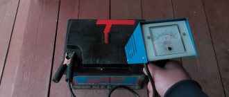
To perform the corresponding check, it is necessary to assemble the circuit shown in the figure. To do this, use a charger or power supply with an adjustable load (it is important that with its help it is possible to regulate the voltage value in the circuit), a 12 V light bulb (for example, from a turn signal or headlight, with a power of 3...4 W), a multimeter, and the regulator itself voltage (this can be from a Bosch, Valeo or other generator). It is advisable to have the wires used for switching with “crocodiles”.
Checking the voltage regulator of the generator 37.3701: 1 - battery; 2 — ground terminal of the voltage regulator; 3 - voltage regulator; 4 – terminal “Ш” of the regulator; 5 — output “B” of the regulator; 6 — control lamp; 7 — terminal “B” of the voltage regulator.
If you assemble a circuit in which the voltage is at a standard value of 12.7 V, then the light bulb will simply glow. But if you use a voltage regulator to raise its value to 14...14.5 V, then if the relay is working, the light should go out. Otherwise the regulator is faulty. That is, when the voltage reaches 14...14.5 V (depending on the model of the machine and, accordingly, the regulator) and above, the light goes out, and when it drops to the same level it lights up again.
It is important that the light does not go out until the voltage supplied to the regulator reaches 14 V. Otherwise, at idle, the generator will not be able to properly recharge the battery.
Checking the VAZ 2107 voltage regulator
Checking the voltage regulator on VAZ 2108/2109 cars
Until 1996, a VAZ 2107 with a 37.3701 generator was equipped with an old-style voltage regulator (17.3702). The verification procedure is given above. After 1996, a more modern generator of the G-222 brand was used (integrated regulator RN Ya112V (V1).
As you can see, the verification algorithm for all regulators is almost the same. The only difference is the cutoff values when the relay is activated.
Reasons for failure of the VAZ 2107 generator
The generator on the “seven” rarely fails, but breakdowns still happen. Therefore, it is worth knowing in more detail how malfunctions manifest themselves.
Breakdown or winding break
Its performance directly depends on the health of the generator coils. With the coils, breakage and short circuit of the turns may occur, breakdown to the housing. If the rotor winding breaks, there will be no battery charge, as indicated by the glowing battery charge light on the dashboard. If the problem lies in the short circuit of the coil to the housing, then such a malfunction mainly occurs where the ends of the windings exit to the slip rings. A stator short circuit occurs due to a violation of the wire insulation. In this situation, the generator will become very hot and will not be able to provide a full charge to the battery. If the stator coils are shorted to the housing, the generator will hum, heat up, and the power will decrease.
Previously, generator windings were rewound when damaged, but now almost no one does this. The part is simply replaced with a new one.
Brush wear
The generator brushes supply voltage to the field winding. Their malfunction leads to unstable charging or its complete absence. If the brushes are faulty:
- consumers often disconnect for unknown reasons;
- lights are dim and flickering;
- the on-board network voltage drops sharply;
- The battery discharges quickly.
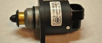
Relay regulator
If, after starting the engine, the voltage at the battery terminals is below 13 V or significantly above 14 V, then the malfunction may be caused by a problem with the voltage regulator. Failure of this device can significantly reduce battery life. If after an overnight stay the starter does not turn or you notice white streaks on the battery itself, then it’s time to diagnose the relay regulator.
Read also: Melting point of different metals
The following problems may occur with this device:
- unreliable contact with brushes;
- breakdown of elements;
- internal open circuit.
There may be no charge due to wear or hanging of the brushes, which is associated with shrinkage of the springs during long-term use.
Diode breakdown
Failure of the diode bridge may be preceded by:
- moisture getting inside the generator;
- dirt and oil;
- “lighting the car” when the battery is completely discharged and the wires are connected incorrectly.
If the integrity of the diodes in the event of “lighting up” depends on the attentiveness of the car owner, then no one is immune from the effects of the first two factors.
Bearings
The VAZ 2107 generator has 2 ball bearings that ensure free rotation of the rotor. Sometimes the generator may make sounds that are uncharacteristic of its operation, such as hum or extraneous noise. Disassembling the generator and lubricating the bearings can only solve the problem temporarily. Therefore, it is best to replace the parts. If they have exhausted their resource, the generator will make a humming sound. You should not delay repairs, since there is a high probability of the unit jamming and stopping the rotor. Bearings can break and hum due to lack of lubrication, excessive wear, or poor workmanship.
Video: how generator bearings make noise
It is quite possible to fix any malfunction of the VAZ “Seven” generator with your own hands. To identify a problem, it is not necessary to have special equipment or have knowledge and skills in working with the electrical equipment of a car, although they will not be superfluous. To test the generator, a digital multimeter or a 12 V light bulb will suffice.
The simplest way to check the generator voltage regulator
The simplest method of checking the regulator is to measure the voltage at the battery terminals with a multimeter. However, it is worth immediately making a reservation that the algorithm given below does not give a 100% probability of failure of the regulator. Perhaps the generator itself has failed. But the advantage of this method is that it is simple and there is no need to dismantle the device from the car. So, the algorithm for checking the generator voltage regulator with a multimeter is as follows:
- Set the tester to DC voltage measurement mode at a limit of about 20 V (depending on the specific model, the main thing is that it displays values up to 20 V as accurately as possible).
- Start the engine.
- Measure the voltage at the battery terminals in idle mode (1000...1500 rpm). If the regulator and generator are working properly, the value should be within 13.2…14 V.
- Increase speed to 2000…2500 rpm. In the normal state of the electrical circuit, the corresponding voltage should be about 13.8 (+-) 0.2 V.
- When the speed increases to 3500 rpm and above, the voltage should not exceed 14.8 V.
If during the test the voltage values are very different from those given, then most likely the machine’s voltage regulator is faulty. Remember that the voltage should not fall below 12V and should not rise above 14.8V.
As mentioned above, the regulator can be separate or combined with a generator. Currently, almost all foreign cars, and most modern domestic cars, have combined relays installed. This is due to the specifics of their work and space saving.
Rotor check
Using a multimeter in resistance measurement mode, ring the excitation winding (on the rotor).
To do this, attach the measuring probes to the slip rings.
The resistance of a serviceable winding should not be in the range of 2.3 -5.1 Ohms.
- If there is no resistance at all, then there is a break in the winding.
- If the resistance is lower than expected, then there is most likely an interturn short circuit.
- If it is higher, then there may be poor contact or the winding leads to the slip rings are not properly soldered.
We also measure the current consumed by the excitation winding. To do this, we apply +12 volts to the slip rings and connect a DC ammeter to the open circuit. The current consumed by the winding should be within 3-4.5 Amperes. If the current is too high, it means there is interturn ignition in the rotor winding and it requires replacement. The maximum current of the relay regulator is 5 Amps, so if the rotor winding current is too high, the voltage regulator also needs to be replaced.
The insulation resistance can be checked with a high alternating voltage of 220 volts by applying voltage through a 220 V, 40 W incandescent lamp, one contact is connected to the slip ring, the other to the metal rotor housing. If there are no short circuits to the housing, the lamp should not light. If the lamp filament glows even just a little, then there is a current leak to ground. This winding requires repair or replacement.
Take precautions when working with high voltage!
VOLTAGE REGULATOR
It is not difficult to find where the VAZ 2114 generator relay is located. This device is located at the back of the generator itself under a plastic cover. Where is the charging relay located on the VAZ 2114 - a question for backfilling. The fact is that the charging relay, generator relay and voltage regulator on the VAZ 14th are generally one and the same single device. It is also called a relay regulator.
What happens if the voltage in an electrical circuit drops below 13.2 Volts? The battery will stop charging, and after a fairly short period of time the starter will no longer have enough power to crank the engine to start. What if it is over 14.7 Volts? Then elements of the electrical circuit may fail, for example, the radio or one of the engine sensors (mass air flow sensor, phase sensor, etc.) will burn out.
The charging relay on the VAZ 2114 looks like a large black tablet, at the end of which there are two graphite brushes (brush assembly). If there is little or no charging, the voltage regulator is checked.
Voltage regulator location
DIAGNOSTICS OF RELAY REGULATOR
Checking the functionality of the generator on a VAZ 2114 always begins by measuring the voltage of the on-board circuit with the engine running. The most convenient way to measure is with a digital multimeter:
- We set up the multimeter to measure voltage and set the upper limit to 20 Volts;
- We connect the probes of the device to the battery and measure the voltage with the engine turned off. The voltmeter should show somewhere between 12.5 and 13 volts;
- We start the engine, the readings of the device with a good working generator should increase to about 14 Volts (maybe a little more);
- With the engine running, turn on the load (high beam, dimensions, heated rear window, heater motor at maximum speed). We look at the readings of the multimeter - the device should not show less than 13.2 Volts at idle, but it is better if this indicator is in the range of 13.8-13.9.
Checking the generator voltage regulator can also be carried out on a removed device. The device assembled with the brush assembly is checked. For this:
- We connect the mass terminal (minus) of the “tablet” with a wire to the minus of the battery.
- We supply power (12-14 Volts) to terminals “B” and “C” from the battery.
- We connect a 1-3 Watt car lamp to graphite brushes. If the relay-regulator is working properly, the lamp should light up.
There is another way to check the operation of the voltage regulator - when you need to check what the regulator's response threshold is at the upper limit. To do this, we increase the voltage in the circuit, for example, in parallel we add two or three 1.5 V AA batteries to the circuit. We need to increase the voltage to more than 16 volts, we connect everything else according to the same circuit. In this case, if the charging relay is working properly, the lamp should no longer light up.
Generator stator
The stator windings can only be examined by disconnecting or unsoldering the leads from the diode bridge. The resistance between the terminals of the windings should be approximately 0.2 Ohm. And between the terminal of any winding and 0 (common terminal) there is about 0.3 Ohm. If the stator windings or diode bridge are shorted, the generator makes a loud noise during operation.
Also carefully inspect the condition of the internal parts of the stator and the outer part of the rotor. They should not touch each other during operation. As they say, “shoes.” During such operation, the generator makes increased noise, which indicates wear of the bearings or bushings.
Video, testing on a homemade stand:
Diode bridge
A diode bridge consists of two plates, one of which is positive and the other negative. Diodes are checked with a multimeter in ohmmeter mode.
Connect one probe to the “+” terminal of the diode bridge, and alternately connect the second to terminals F1 F2 F3 and 0. To make it clearer: we connect one probe to the positive plate, and with the other we alternately touch the terminals of those diodes that are pressed into this plate.
Then swap the probes and do the same. In one case the tester should show conductivity (some kind of resistance), but in the other it should not. So we checked the diodes on the positive plate.
Read also: How to determine the primary winding of a step-down transformer
To check the diodes on the negative plate, connect one probe to the negative plate, and the second to the leads of the diodes alternately. In exactly the same way, then we swap the probes and repeat the procedure. In one case there will be conductivity, in the other there will not be.
Checking the car battery and generator
Carry out measurements using a FIRM BMW TESTER.
| Check the rotor winding for open circuits and interturn short circuits. |
Attach the cable for measuring resistance to the slip rings.
— 140 A = 2.65 WB
| Check the rotor winding for a short to ground. |
Attach the cable for measuring resistance to the slip ring and the rotor shaft.
Set value: corresponds to indication 999 kW
| Check the stator winding for short to ground. |
Attach the cable for measuring resistance to the soldering point and to the stator (winding frame).
Set value: corresponds to indication 999 kW
| Check the stator winding for continuity: |
Check the resistance values of wires 1/2, 1/3 and 2/3 using an ohmmeter, they should be the same.
The turn-to-turn test can be performed using a conventional test probe.
| Checking negative diodes: |
Connect the diode test cable.
Attach the negative cable to the cooler, and the positive cable to the connection of one of the negative diodes.
Indication with working diodes:
polarity "-".
| Checking positive diodes: |
Attach the negative cable to the contact bolt B +, and the positive cable to the connection of one of the positive diodes.
Brushes and slip rings
Rings and brushes can be checked visually, assessing their condition and serviceability. Check the protruding length of the brushes. It must be at least 4.5 mm. And the norm is 8-10 mm.
Also, the diameter of the slip rings must be at least 12.8 mm. and ideally 14.2-14.4. Worn rings can be replaced if you find them in a store. They are removed with a special puller, and the winding terminals are unsoldered. After installing new rings, they can be turned on a lathe to eliminate runout and sanded with fine sandpaper to eliminate burrs.
In general, the voltage regulator in my generator has failed. I ordered and installed a new one. And I decided to take apart the burnt one and see what was there. As a result, it seemed to me that the transistor had become unsoldered. Because I slightly poked it with a knife and it moved away from the board. And there was a black coating on the soldering at the point of contact with the transistor. In the end, I soldered everything back and put it back together. Now I’m wondering how to check performance at home. Maybe someone has already encountered this and can advise? Regulator photo:
PS: Thank you all very much in advance for your help!
Comments 40
I can suggest, it’s all simple, you hang a 5W lamp on the brushes and supply power from +5, the lamp turns on at 14.5, it turns off if it doesn’t fall within this interval, throw it away or look for where the jamb is, usually the power transistor flies out to replace it, if it’s a field-effect one you’ll have to also look at the power diode
Thank you. Already figured it out. I removed the radiator on the regulator and the power transistor practically fell out, i.e. the soldering has come off. I soldered everything and assembled it. Works like new, even better))))
But you can’t ring the transistor itself, or what?
If it’s assembly then it’s not possible.
This means it is unusable, most likely the transistor is broken, throw it away.
You can’t check on the table without certain skills. E ground, B output from power diodes, P phase voltage, here you need to put a signal from a generator (not a car, but a laboratory one) and then, if the regulator relay is working properly, the light on the brushes will light up...
I ended up connecting the plus to B and L and the minus to E at home. The lamp lit up. Then I connected 19 volts, the lamp was still on and the regulator got very hot
19 is a lot. Did you measure the voltage with a tester? Logically, the light bulb should always be on, it’s just that the brightness cannot be determined above a certain limit. The principle is simple. The brushes supply excitation voltage for the generator. Depending on the current consumed (load), the voltage at the generator output will change, in particular, as the load current increases, the voltage at the generator output will drop. In order to increase it, it is necessary to increase the voltage on the excitation winding, those on the brushes. The load current decreases and the voltage at the generator output begins to increase. To reduce it, it is necessary to reduce the voltage on the excitation winding. If no voltage is applied to the excitation winding at all, then there will be nothing at the output of the generator. If it is completely scientific, then the output stage of the generator relay is designed according to an open collector circuit. This means that if the brushes are not loaded with anything, then there will be no current through them. And if the load resistance is less than the operating resistance (in this case, the load resistance is the light bulb and not the generator winding), then the current through the transistor will be higher than the nominal one and it will get very hot. A comrade from Kharkov recommends throwing it away, I don’t agree with him. Once again, I recommend connecting a voltmeter in parallel to the light bulb and checking whether the voltage on the brushes changes. Regarding L. This is a control wire. Voltage is not applied to it, but removed. This is the output that connects to the charge control lamp. It has a tricky connection (through the middle point of the generator windings, there are three of them and they are connected by a star)... In short, in order not to fuss your brain, connect to B +, to P or E - and to the brushes a light bulb and a voltmeter. Apply 12 V to the input and see what voltage is on the brushes. Then apply 14-16 V and see what voltage is on the brushes. If it has changed, the relay is working, if not, the output transistor has burned out. In principle, it can be changed. But if you are in radio engineering like a hare in oranges, then it is better to ask someone knowledgeable to select an analogue of this transistor. But most likely there is not a transistor but an assembly, and therefore this is a completely different story, you will need to look for exactly the same one. By the way, what is your operating voltage, maybe you can put a tablet from another RR there?
I ended up connecting the plus to B and L and the minus to E at home. The lamp lit up. Then I connected 19 volts, the lamp was still on and the regulator got very hot
For you and everyone else: - these generators do not have additional diodes, and relay regulators measure the phase voltage from the windings i.e. waiting for change! voltage to input P, which can be supplied to the table from a laboratory generator, since both the frequency and voltage on it will have to be changed.