How to assemble a UAZ rear axle
Assemble the differential in the following order:
1. Before assembling the differential, lubricate the axle gears, satellites, thrust washers and satellite axles with transmission oil
2. Install thrust washers on the journals of the axle gears.
3. Install the axle gear with thrust washer assembly into the left gear box.
4. Install the satellites on the axis of the split cross.
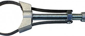
Rice. 7. Pressing out the outer ring of the differential bearing
5. Install the detachable crosspiece (Fig. 1) with satellites into the left satellite box.
Rice. 8. Installation of satellite boxes according to marks
6. Install the axle gear with thrust washer assembly into the right gear box.
Holding the axle shaft gear, install the right satellite cup onto the left one so that the marks (Fig. 2) (serial numbers) of both cups are aligned.
7. Connect the halves with bolts and tighten them. Tightening torque 32–40 Nm (3.2–4.0 kgf).
Rice. 20. Rear axle
8. Install the main drive driven gear onto the gearbox, aligning the bolt holes. Install the bolts and tighten them.
Tightening torque 98–137 N m (10–14 kgf m).
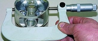
For the assembled differential, the axle gears must be rotated using a splined mandrel from a force of no more than 59 N (6 kgf) applied over a radius of 80 mm.
Adjust the differential bearings (if they are replaced) in the following order:
Rice. 9. Pre-pressing of the inner rings of the differential bearings
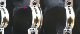
1. Press the inner rings of the bearings (Fig. 9) of the differential onto the journals of the assembled differential so that there is a gap of 3.5–4.0 mm between the ends of the gearbox and the ends of the inner rings of the bearings.
Rice. 10. Rolling in differential bearing rollers
Dismantling the rear axle UAZ
In the article we will consider removing the axle shaft, replacing and adjusting the hub bearings, and removing the rear axle
Removing the axle shaft
We hang the rear wheel or the entire rear axle and remove the rear wheel for convenience
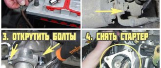
Using a 14mm head, unscrew the ten bolts securing the axle flange to the hub.
We attach bolts with M10 threads into two threaded holes of the flange
Tighten the bolts evenly, tearing the axle shaft flange off the hub, and remove the axle shaft
A paper gasket is installed between the hub and the flange
Install the axle shaft in reverse order
Adjusting the wheel bearings
We hang the rear wheel and remove the axle shaft as indicated above
Use a chisel to bend the edge of the lock washer
Using a 55mm tubular wrench, unscrew the bearing lock nut and remove it
Use a screwdriver to pry it off and remove the lock washer. It is installed with a folding mustache outward
We tighten the hub adjusting nut until it stops, constantly turning the hub by hand to self-install the rollers in the bearings
Unscrew the adjusting nut 1/4–1/3 turn. Install the lock washer, screw and tighten the lock nut
We check the bearing adjustment by rotating the hub by hand. It should rotate freely, without jamming, clicking or play.
We adjust the hub bearings of other wheels in the same way.
Using a chisel, bend the edge of the lock washer onto the edge of the locknut. We finally check that the bearings are adjusted correctly by driving 5–10 km without heavy braking.
If the hub gets very hot (the hand does not tolerate it), loosen the adjusting nut by 1/6 of a turn, as indicated above
If the hub continues to heat up while driving, the bearings may be damaged or lack lubrication.
Replacing bearings and hub cuffs
Remove the axle shaft as indicated above
Unscrew the hub locknut and remove the lock washer
Using a 55mm tubular wrench, unscrew and remove the bearing adjusting nut
Use a screwdriver to pry it off and remove the lock washer.
We pull the hub together with the bearings and brake drum from the axle housing
If the brake pads interfere with removing the hub, then by rotating the eccentric bolts, we bring the pads together
We remove the inner ring of the bearing with rollers
Use a screwdriver to pry up and remove the hub cuff
We remove the spacer ring installed under the cuff and the inner ring of the inner bearing
Using a soft metal drift, use a hammer to press the outer ring of the inner bearing out of the hub and remove the ring
Use pliers to squeeze the ends of the retaining ring of the inner bearing and remove the ring.
Similarly, press out the outer bearing ring and remove the retaining ring.
We wash the inner cavity of the hub and other parts with kerosene or diesel fuel
Lubricate the bearing seats with transmission oil
We install the bearings in the reverse order, generously covering their rings and rollers with Litol-24 or other lubricant
We place the same lubricant between the bearings in a layer 10–15 mm thick.
Install the hub and adjust the bearings
Removing the rear axle
Loosen the rear wheel nuts
We hang up the rear of the car and install reliable supports under the car frame in front of the rear axle
Drain the oil from the gearbox
Removing the rear brake hose
Disconnect the driveshaft from the bridge
We install jacks under the bridge beam.
Unscrew the nuts of the spring ladders, remove the spring linings and linings
Having removed the wheels, lower the rear axle onto the cart and roll it out from under the car
If there is no trolley, the bridge can be rolled out on its wheels (we do not remove them for this)
We install the bridge and the removed parts in the reverse order
Fill the main gearbox with oil and bleed the brake system
We finally tighten the nuts of the spring ladders in the “car on wheels” position
Rear axle disassembly
For ease of use, first:
— remove both axle shafts;
- remove and disassemble the rear wheel hubs
We disassemble the main gear reducer, assemble it, adjust the bearings and the clearance in the meshing of the main gears
Rear axle structure of UAZ 469
The device of this node
The Soviet SUV UAZ 469, produced by the Ulyanovsk Automobile Plant, is unique in its own way. The diagram of the rear axle of the machine is shown in Fig. 1. The design includes the following key components and assemblies:
- 1 — protective overlap;
- 2 — roller bearing of the differential device;
- 3, 8 — corrective auto-linings;
- 4 — tail part of the drive gear support;
- 5 — adjustment ring;
- 6 - oil removal holder;
- 7 - nut;
- 9 — front gear of the rear axle;
- 10 — head bearing support;
- 11 — hydraulic washer of the gear wheel axle shaft;
- 12 - gear element.
UAZ rear axle bulkhead
To assemble a “military” (with final drives) bridge, you need to perform the following steps:
A)
Pressing in the outer rings of all bearings and assembling the satellite box:
1) Completely clean the inside of the axle halves from old oil and dirt. Wash the bridge cavities with solvent.
2) Press the outer rings of the differential bearings into both halves of the axle. Pressing is carried out through a spacer sleeve, for example, an old outer ring of a bearing
3) Press the outer rings of the drive gear bearings into the axle housing.
Outside, you can use 10mm plywood as a spacer
To make pressing easier, you can apply a couple of drops of oil to the outer rings of the bearings and rub them with your finger over the entire surface.
All outer rings are pressed until they are fully seated.
4) Press the bearings onto the journals of the satellite box so that there is a gap of 3-4mm between the ends of the bearings and the satellite box
Be careful when you press on the second bearing. You cannot rest the gearbox on an already pressed bearing, because... it may shift. That is, as shown in the photo, you cannot press on the second bearing.
5) Install the gear box with bearings into the axle housing. Rotate one of the axle halves (the smaller one, the so-called “stocking”) relative to the axle housing to self-install the bearing rollers.
Lift the stocking and install the gasket between the bridge halves. Align the spring pads of the bridge in one plane and evenly tighten the halves of the bridge with a torque of 70-80 N * m.
6) Disassemble the bridge again. Remove the satellite box and use a set of feeler gauges to measure the distances between the ends of the bearings and the satellite box (the previously set gap is 3-4mm). Let's call these distances A and A1. Using the formula B = A + A1 + 0.1, we calculate the required thickness of the gaskets.
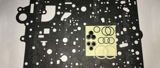
7) We divide this distance B approximately in half. Accordingly, we assemble 2 sets of shims. It is advisable to assemble a package of thin gaskets. Gaskets come in thicknesses of 0.1mm, 0.15mm, 0.25mm and 0.5mm. It is better to measure the two packs of gaskets assembled in this way with a micrometer in order to make sure the sizes match.
 We press the bearings (only a two-legged puller is suitable; in the satellite box there are 2 special recesses for its legs)
And install under each selected gasket package
B) Assembling the drive gear (we do not install the gearbox in the axle housing yet):
1) Using a micrometer, measure the height of the old bearing closest to the drive gear teeth. Measure the height of the new bearing. Let’s call the difference in height between the new and old bearings the value “A”. If the old bearing is lower than the new one by the amount “A”, then it is necessary to increase the thickness of the adjusting washer located between this bearing and the teeth of the drive gear. If the new bearing is lower than the old one, then increase the height of this washer by this value “A”. The washers are produced in increments of 0.05mm.
If the height of the bearings is the same, then you can install the old washer.
2) Place the selected (or old) washer and press the new bearing onto the drive gear shaft. Next, install a new spacer sleeve and another adjusting washer. The height of the new and old spacers must also be measured. If they are different, then you cannot install the old shim (which is located between the spacer sleeve and the outer bearing). It is necessary to select this washer so as to compensate for the difference in the height of the spacer sleeves. The height of the new bushing is less, then the adjusting washer should be thicker by this amount. And vice versa.
3) Install the drive gear into the axle housing, press on the second bearing, install a washer with an internal sprocket, DO NOT INSTALL the oil seal, but install a flange. The oil seal cannot be installed because it will distort when measuring the breakaway torque.
The flange nut must be tightened with a force of 160 N * m. After tightening the nut, the breaking torque should be measured. It should be within 25-40 H * m. The moment of breaking can be measured with an ordinary household steelyard. The correct starting moment is in the range of 2.5-4kg.
5) If the breakaway moment is greater, then it is necessary to add shims between the outer bearing and the spacer sleeve. And vice versa. The spacers come in 0.05mm increments.
6) Mark the relative position of the nut and flange. Remove the flange and press in the drive gear oil seal. Install the flange.
7) Tighten the flange nut until the marked position is achieved again. We pin it.
B) Adjusting the GP gap:
1) Install the gearbox with adjusted bearings into the axle housing (the drive gear is already installed). Next, we apply paint (you can use any paint, but there are special ones on sale for adjusting the side clearances) on the teeth of the driven (large) gear.
We assemble both halves of the bridge with the gasket, tighten them with bolts with a force of 70-80 N * m.
2) Rotate the flange in both directions long enough.
3) We disassemble the bridge. And look at the contact patch that appears on the paint.
Drawings of correct and incorrect spots should be looked at in the manual.
4) If the lateral clearance spot of the GP is incorrect, then by rearranging the gaskets under the bearings of the satellite box, the satellite box is moved closer and further from the drive gear
By changing the thickness of the gasket under the large bearing of the drive gear, it thereby moves deeper into the bridge (i.e. closer to the satellite box) or outward. The thicker the washer, the more the drive gear extends outward and vice versa.
5) Having achieved the correct contact patch, you can install the axle shafts and assemble the final drive.
Arrangement and elimination of rear axle breakdowns
The rear axle is a support; inside it is the main transmission of the axle shaft, the differential. It can be of two categories: with a single main gear or an additional wheel drive. Wheel regulators, which increase torque and transmit it to the hubs of the conductive wheels, are located at the ends of the beam.
Wheel roller bearings rest on the regulator housings. Wheel gearboxes provide enormous ground clearance and are gears meshed internally. The main gear is bevel, with a spiral tooth, a bearing unit, which has a main gear and a bevel drive with 4 satellites. A satellite is a gear, compact, simple, rarely fails, and facilitates quick, easy gear changes.
The crankcase has a drain and fill hole and contains a certain amount of oil to lubricate the wheel hydraulic adjuster.
The rear converter support is detachable and consists of elements such as a cover, contamination protection, and pressed-in axle shaft housings. Its dimensions have been reduced, the gear ratio has been reduced to 2.77.
The driven rear axle gearbox is mounted on the shaft. It is installed in a roller bearing and bushing, tightened with a nut, and secured into the groove of the shaft. The ends of the gearbox shafts have movable couplings that help group and separate the shafts from the wheel hubs if necessary.
When the clutches are disconnected, the UAZ 469 becomes rear-wheel drive. This is useful on good paved roads. When driving in impassable terrain, turning off is not advisable. You can disconnect and connect the hubs from the start of operation of the quick response clutch or the hub cam. In this case, you do not need to crawl under the bottom of the car.
Features of unit dismantling
When removing the rear axle, you need to unscrew the tail unit nut, remove the washer, mating flange, cover of the front gear roller assembly, and press the assembled gear with bearings out of the oil cooler at the rear of the car.
This circuit is excellent for disassembling a differential device. The next step is to unscrew the splines connecting the driven gear to the gearbox and reset it. Divide both parts of the box, pull out the gears, planetary gear rods, and support nuts. When assessing disassembly, pay attention to the integrity of the gear wheel teeth. If they are damaged, the part must be replaced. To remove rollers, outer and inner rings, special tools are required. Strictly study and understand the disassembly sequence so that you can accurately perform all steps in reverse order when reassembling.
When inspecting the oil stripper ring, check for surface irregularities. If yes, process to a thickness of 5 mm. The same goes for the cardan flange. Grinding height up to 53 mm. Wash the protective surfaces. Blow out the oil outlets. Drive design parts and axle shafts should be replaced if there are scuff marks or severe wear.
Removing a faulty unit
Since the UAZ 3741 has a frame structure, the front axle can be removed quite easily. To do this, you need to stock up on a powerful jack, stops that can support 1.5 tons of the front of the car, and WD-40 - a liquid for loosening nuts.
The procedure is as follows:
- First you need to install chocks under the rear wheels of the car.
- After this, you should disconnect the left and right brake pipes from the hoses going to the front wheel drums.
- Then you need to unscrew the nuts securing the brake hoses and remove the hoses themselves.
- Next, unscrew the nuts securing the lower ends of the shock absorbers.
- Remove the bolts connecting the drive gear flange to. front driveshaft.
- Then you should undo the cotter pin and unscrew the bipod ball pin nut.
- Disconnect the rod from the bipod.
- Unscrew the nuts that secure the front spring stepladders and remove the stepladders with pads and pads.
- At the end, you need to lift the front of the car by the frame and pull the bridge out from under the car.
When the old bridge is removed, you can proceed to installing a new part by performing the reverse procedure. If necessary, the removed unit is disassembled, troubleshooting is carried out, damaged parts are replaced, and then the bridge is returned to its place.
Nuances of installation and adjustment
The assembly (diagram) of the differential drive structure is carried out as follows.
- Connection of both satellite boxes depending on the case serial number.
- A crosspiece is inserted into the left satellite box.
- Place the assembled gear in the left box.
- Lubricate the differential units (axle gears, satellites, axles, thrust washers) with transmission oil.
- Secure the necks of the gear rings of the axle shafts with support washers.
- The satellites must be secured to the axis of the disconnected cross.
- Carry out the same actions with the right box.
- Tighten the parts of the boxes, insert the driven wheel of the base gear.
The foreman goes through the unit
Turn the six axle shafts of the mounted differential using splines with a force of no more than 59 N. Adjustment of the drive structural elements is carried out when replacing them.
- Secure the inner rings of the differential bearing units to the journals; the end play between the box and the rings should approach 3.5-4.0 mm.
- The installed differential differential is closed with an auto-gasket and a reservoir cap. Roll the bearings to establish the correct position. Secure the heat exchanger lock.
Forward and reverse torques
- Precise engagement in engagement with low load.
- Microcontact on top of the tooth (when debugging, move the head part towards the driven part).
- Contacting at the root of the clove (correction: the conductive one should move away from the driven one).
- Block contact is the narrow end of a tooth (deviation of elements from each other).
- Contact on the volumetric side of the tooth (deviation of the driven to the leading).
The gasket set is installed between the valve end of the front bearing assembly, the wheel and the axle support. The thickness of the package is a gap not exceeding 1.3.
Important parts of the unit
Secure the outer bearing lock assembly with the cuff with bolts, install the flange, and secure the washer with a cotter pin. A prefabricated differential is installed in the unit pan, then oil seals between the crankcase and the damper. The top of the pallet is mounted taking into account the spring pads located in the outer portion of the bridge.
The mounted bridge should not heat up while the machine is moving. Correctly adjusted parts will not cause heating. Of course, you just need to check that the driven gears are not jammed or caught, if the device has any.
Installation, adjustment, and repairs must be carried out on time. Safety when driving in a car depends on this. Maintenance of the UAZ bridge part is as follows.
- Constantly maintain the technical level, timely change the oil, check the seals, detect and eliminate axial gear play in the head drive of the unit. Systematically monitor the adhesion of fastening parts of components and assemblies.
- Pay great attention to cleaning the safety valve. If the oil is dirty or contains iron impurities, the heat exchanger should be flushed with kerosene before replacing it.
Experienced drivers recommend pouring 1 liter of gasoline into the pan, raising the wheels, connecting the engine, letting it run for 1-2 minutes, then draining the remaining gasoline, draining it, and pouring clean motor oil into the tank.
How the UAZ front axle works: detailed instructions for maintenance and repair
UAZ is a legendary SUV, popular both in Russia and beyond its borders. The car has been produced for quite a long time, which has proven the reliability of its design. This machine is actively used in the army. There are minor differences between the civilian and military versions. However, both here and there the UAZ front axle showed its best side. There are several modifications: on-board, regular, “loaf”, etc. Also, one cannot fail to note one of the advantages of the car - maintainability and the ability to restore the functionality of any unit, even in “garage” conditions. The mechanism allows you to activate all-wheel drive, which helps you confidently overcome obstacles.
UAZ bridges
Many axle options were installed at the factory on UAZ vehicles of different models and at different times. Let's try to figure this out...
UAZ Timken bridge (civilian or collective farm)
This is a split type bridge, that is, a bridge consisting of two halves. A military bridge (also known as a gear or portal bridge) can also be classified as this type. From the factory, civilian axles are installed on UAZ trucks of the cargo range (loaf, flatbed, farmer), as well as on passenger cars of the UAZ-3151 (469) range.
UAZ front axle structure
It consists of a crankcase (sometimes called a stocking), a differential and a final drive. The rear and front axles have no fundamental differences. The only difference is in the direction of the thread of the oil rejection ring located in the main gear. The current design of the UAZ front axle is shown in the picture below. The support placed on the casing is fixed with five hardware. Pin bushings are pressed into the support. A pair of pins “engages” in holding the fist. He also holds the housing cover of the wheel gearboxes. A pin is fixed on it along with a shield on which there are parts of the brake system.
The pins do not rotate in the fist thanks to pin-type stoppers. The fist itself is made with preload (0.02-0.1 mm). The UAZ 469 axle is adjusted using spacers. Location: between the turn lever and the trim (left or right). The spacers are located between the pads and the fist.
One of the features of the described mechanism is that, in addition to increasing cross-country ability, it also turns the wheels. For this purpose, Birnfield ball joints are used. Their cavities contain lubricant that does not need to be replenished throughout their entire service life. The cams, as well as the axis of the pins, are inclined, which allows the wheels to be returned to the middle position after making a turn. The main advantages of the beam (Spicer):
- track is 1.6 m, which has a positive effect on the stability of the car;
- the wheels rotate at an angle of up to 32 degrees, which gives the machine improved maneuverability;
- instead of leaf springs, a dependent suspension on springs is mounted;
- no need to replace lubricant in mechanisms (fists);
- removable cover facilitates access to parts in case of repair;
- the differential together with the gearbox are in one housing - this increases rigidity and service life;
- An improved satellite gear has reduced noise.
Particularly worth mentioning are the hinges, or more precisely the stabilization of angular velocity. This is a design that ensures the stability of rotation of two shafts: the drive and the accompanying. The hinge includes two forks: in their sockets there are 4 balls. In the middle sectors of the parts there is a fifth one, needed for installation operations. In particular, centering the fork. To deactivate the front-wheel drive, there is a special device consisting of a clutch, bolts, and balls.
Distinctive features of the military version
The main feature of the front axle in the military version is the placement of the gearbox. It is located higher. The second distinctive point is the gear ratio - 5.38. The civilian version of UAZ 469, 452, 3151, 3303 has 4.6 or 5.125. All these characteristics increase the distance from the bottom of the car to the road surface from 220 to 300 mm. Those who want to quickly replace an ordinary bridge with a military one will be disappointed: this will not work without alterations. The reason is in the design of the bipod and suspension. In addition, driveshafts differ in length.
Front axle UAZ 469
The design of the front axle is different from that of the rear axle. The crankcase is shifted to the right edge in the direction of travel of the car. This is due to the location of the transfer case. The front axle is driven by a driveshaft from the drive shaft. The axle is equipped with rotating mechanisms and steering rods that are used to control the vehicle.
The driver can turn on the front axle on the UAZ 469 without leaving the cabin. To do this, transfer case control levers are installed between the driver and passenger seats. One lever is responsible for turning the front axle on and off. The second is necessary to reduce torque transmission.
Half shafts
The axle shafts have different lengths. This is due to the location of the gearbox. To transmit torque to the wheel mechanisms, regardless of the angle of rotation, CV joints are provided.
IMPORTANT: The design of the front axle of the UAZ 469 provides for disconnecting the axle shafts from the wheel hubs. The connection is made with a specialized screw. This design allows you to increase the service life of the gearbox when driving on good quality surfaces and saves fuel.
Carter
The front axle housing is made of two parts connected by bolts. To avoid pressure build-up when the lubricant heats up, the crankcase is equipped with a breather valve. It allows the air mass to freely escape into the atmosphere. The breathing valve is protected from dust and contamination by a cap.
Steering
The wheel mechanisms are connected to each other by a transverse rod. The rod connection is hinged. To adjust the wheel toe angle, the rod is equipped with ends with threaded connections.
Maintenance
Maintenance of the UAZ bridge is simple and comes down to monitoring the level of lubricant and topping it up and replacing it. The second point is to check the seals for leaks. It is regularly necessary to check the reliability of the fastenings, especially if the machine is used in difficult road conditions. Eliminate axial play in the differential bearings in a timely manner.
Assembly and connection diagram
When assembling the structure, do not remember several features:
- Press the bushing into the trunnion flush with the end of the washer socket. After completing the procedure, the sleeve must be deployed;
- Place one thrust washer inside the trunnion, the second - in the support. The oil lines in the thrust washers should face the joint. The washer is secured by punching in 3-4 places;
- When installing the hinge, add lubricant to the ball joint;
- Treat the pins and bushings with liquid lubricant.
To obtain the required axial tension, you need to select a certain number of spacers (but not less than five). They are installed on the ends of the knuckle body at the top and bottom. Their number should be the same. Soak the felt ring of the ball joint oil seal with engine oil. If possible, check the bridge on a bench after assembly. If the assembly is done correctly, the axle shafts should not heat up or make excessive noise when braking. Leaks through seals, cuffs, and bolted connections are not allowed.
How to disassemble a bridge
The first step is to remove the brake drum. Next, the hubs and hubs are dismantled. Along the way, inspect the bearings, which may have worn out and will have to buy new ones.
- Unscrew the brake system hose, it will get in the way, and remove the brake shield;
- Pull out the CV joint;
- Remove the rotating mechanism and shank;
- Divide the stocking into two parts;
- Remove the pair from one part of the bridge and the other.
Front axle structure of UAZ 469: connection diagram
Assembly and connection of the part in question is carried out in the following order:
- The bushing is inserted into the knuckle axle using the pressing method. It should be flush with the end of the seat. The sleeve is then rotated and adjusted with a special brooch to the required diameter.
- Limitation of the movement of the hinge at identical angular longitudinal velocities is ensured by washers installed in the trunnion and ball joint. Their location should be directed with the lubrication grooves towards the hinge. The fixing washer is attached by punching in several places at points evenly distributed around the circumference.
- Replacing the pin bushings involves pressing and screwing them to a diameter of 25 mm, with the ability to pass through each bushing.
- When installing the hinge, lubricant is poured into the support.
- The design of the front axle on the UAZ 469 involves adjusting the required axial tensions using adjusting inserts, which determine the location of the bushings and the ball joint itself. A minimum of five gaskets are used. The total thickness indicators at the top and bottom should not have a difference of more than 0.1 mm.
- Before assembling the oil seal, the felt ring is soaked in warm engine oil.
After assembling the front axle, it is tested on a stand in a static state and under load. This position is created by synchronously braking the axle shafts. If the unit is assembled correctly, there will be no increased noise of the unit, no oil leakage in the oil seals and cuffs, as well as joints.
Repair of the most common faults
Restoring the bridge to operability is not very difficult: but it is required to be careful when performing operations. What “diseases” are most common?
Leak formation
Where the steering knuckle connects to the bridge, there is an oil seal - one of the weak points of the design in terms of lubricant leakage. The oil seal can leak oil not only due to wear, but also when the breather is clogged. If you add more lubricant than required, the result will be the same: a leak. There are two types of oil seals:
- rubber: inexpensive, but also short-lived;
- polyurethane: more expensive, have a long service life.
To replace a part, place the car on a level place and jack up the problem side, loosening the wheel nuts in advance. Further:
- remove the steering knuckle;
- clamp the part in a vice;
- pull out the oil seal by prying it with a flat screwdriver or other suitable tool;
- pull the oil seal out of the support cavity;
- Lubricate the seal before installation;
- press in the oil seal using a tube of the appropriate diameter.
- Installation is in the reverse order.
The mechanism began to hum
First of all, check the oil level. If it is normal, the bridge will have to be removed and disassembled. If the bridge hums constantly in any driving mode, the reasons may be as follows:
- incorrect setting or limiting service life of differential bearings;
- breakage (wear) of the axle shaft (its bearing);
- wear, damage, incorrect gear adjustment.
These bearings simply need to be replaced with new ones. If a humming noise appears during a sudden stop or acceleration, the reasons are as follows:
- incorrect clearance between the final drive gears;
- The final drive gear teeth do not mesh correctly.
In this case, you need to correctly adjust the gearing or replace defective parts. If the bridge hums when the UAZ enters a turn and moves in a straight line, the reasons may be the following:
- satellites rotate with great effort;
- abnormal operation of the axle gears in the differential;
- destruction, severe wear of the axle bearing;
- incorrect clearance between gears located in the differential.
To restore the functionality of the mechanism, adjust the clearances correctly and replace damaged, worn bearings. It is worth noting that the desired result when adjusting the gaps can only be achieved on a bench.
Wheel axial play
It occurs when the wheel bearings are incorrectly adjusted or when they completely fail, which is caused by over-tightening. As a result, the bearings become very hot, the smear liquefies and flows out. Algorithm of actions when performing the correct adjustment:
- Jack up the wheel on the desired side;
- Use a puller to remove the axle shaft;
- Move the lock washer to the side and unscrew the lock nut;
- Spin the wheel: if it rotates tightly, the reason may lie in jamming of the cuffs, contact of the drum and pads, etc.;
- Tighten the adjusting nut. Do this gradually while spinning the wheel. Use the WRENCH;
- Unscrew the nut about a third of a turn and install the lock washer. Tighten the nut and lock it;
- Check how the wheel rotates: it should spin freely without sticking;
- Replace the axle shaft, replace the bolts and tighten them.
You can finally check while moving. If the hub gets very hot, loosen the hub nut about 1/6 of a turn.
Disassembling the steering knuckle without dismantling the bridge
To perform this operation, first disconnect the hub by unscrewing the 6 bolts. Then bend back the lock washer, unscrew the hub nuts and remove it with the wheel and drum. Further:
- disconnect the oil deflector by unscrewing 6 bolts;
- remove a couple of bolts on the steering knuckle, hang the brake shield on the spring;
- remove 6 bolts to disconnect the cover and the knuckle body;
- to remove it, unscrew the bolts and remove the o-rings;
- Unscrew the knuckle linings, remove the kingpins and remove the steering knuckle housing.
As you can see, it is quite possible to repair the front axle of a UAZ with your own hands. However, you need to have experience in carrying out such work and a good set of tools.
Repair of bridges on UAZ 469
Many Internet users enter a similar request in Yandex or Google - “repair of the front axle of UAZ 469”. This means that they are interested in how to repair the front or rear axle on a UAZ themselves. Of course, the procedure for dismantling and repairing the bridge is described in special books on repair and operation, which are now not a problem to obtain. However, disassembling with your own hands both the front and rear axles down to the last screw is, to put it mildly, not an easy task. It may turn out that you just need to replace some small part, to access which you don’t have to disassemble everything.
Front axle UAZ 469
Here are just some possible options for bridge failures on the UAZ 469 (Hunter, Patriot, “loaf”):
- The differential is worn out, the gear housing is bent
- Critical wear of the main gear in the gearbox
- Wear of the steering knuckle (ball joint, axle) on the front axle
- The appearance of large gaps in the pivot joints
- Bearing wear, resulting in the need for adjustment or replacement
- Injection of elements requiring lubrication
It can be difficult to understand which of the above happened to your car, however, it is often possible to roughly localize the problem even by ear. If you hear increased noise or a hum from the front or rear axle (even in neutral gear), the gearbox is most likely worn out (needs repair), or the bearings require lubrication. If your car “yaws” from side to side and the steering is fine, the problem may be stuck in the axle, CV joint, or incorrect installation of the pins that secure the ball joint, as a result of which play appears and the wheel begins to “walk.”
What does a CV joint consist of?
A very common malfunction is the flyout of the ball bearings that are located in the CV joint. They fly out precisely because of incorrect adjustment of the pins, as a result of which the geometric center of the CV joint and the axle do not coincide. As a result, the axle shaft “walks” in the seat and gradually breaks down. The CV joint itself is also damaged. And when turning, you can hear a crunching sound from the side of the wheel and the wheel may jam. During the repair process, some craftsmen simply throw out all the balls, except for the centering one (additionally welding it) - in order to get rid of the problem of their constant flying out.
Rear axle structure of UAZ 469
The device of this node
The Soviet SUV UAZ 469, produced by the Ulyanovsk Automobile Plant, is unique in its own way. The diagram of the rear axle of the machine is shown in Fig. 1. The design includes the following key components and assemblies:
- 1 — protective overlap;
- 2 — roller bearing of the differential device;
- 3, 8 — corrective auto-linings;
- 4 — tail part of the drive gear support;
- 5 — adjustment ring;
- 6 - oil removal holder;
- 7 - nut;
- 9 — front gear of the rear axle;
- 10 — head bearing support;
- 11 — hydraulic washer of the gear wheel axle shaft;
- 12 - gear element.
Arrangement and elimination of rear axle breakdowns
The rear axle is a support; inside it is the main transmission of the axle shaft, the differential. It can be of two categories: with a single main gear or an additional wheel drive. Wheel regulators, which increase torque and transmit it to the hubs of the conductive wheels, are located at the ends of the beam.
Wheel roller bearings rest on the regulator housings. Wheel gearboxes provide enormous ground clearance and are gears meshed internally. The main gear is bevel, with a spiral tooth, a bearing unit, which has a main gear and a bevel drive with 4 satellites. A satellite is a gear, compact, simple, rarely fails, and facilitates quick, easy gear changes.
The crankcase has a drain and fill hole and contains a certain amount of oil to lubricate the wheel hydraulic adjuster.
The rear converter support is detachable and consists of elements such as a cover, contamination protection, and pressed-in axle shaft housings. Its dimensions have been reduced, the gear ratio has been reduced to 2.77.
The driven rear axle gearbox is mounted on the shaft. It is installed in a roller bearing and bushing, tightened with a nut, and secured into the groove of the shaft. The ends of the gearbox shafts have movable couplings that help group and separate the shafts from the wheel hubs if necessary.
When the clutches are disconnected, the UAZ 469 becomes rear-wheel drive. This is useful on good paved roads. When driving in impassable terrain, turning off is not advisable. You can disconnect and connect the hubs from the start of operation of the quick response clutch or the hub cam. In this case, you do not need to crawl under the bottom of the car.
Installation and repair of the UAZ rear axle
- Installation and repair of the UAZ rear axle
- UAZ rear axle structure
- Rear axle adjustment
- Possible causes of malfunctions and their elimination
- Increased noise when driving
- Knocking sound when pressing the throttle pedal
- Oil leaks
- How to remove the rear axle of a UAZ
- Assembly and disassembly of the rear axle on a UAZ
The rear axle is a machine mechanism that connects the wheels of the rear axle and serves as its support. The bridge is attached to the machine frame or to its body using a suspension.
- UAZ rear axle structure
- Rear axle adjustment
- Possible causes of malfunctions and their elimination Increased noise when driving
- Knocking sound when pressing the throttle pedal
- Oil leaks
UAZ rear axle structure
The UAZ rear axle structure includes many elements. Main parts of the structure: differential, axle shafts, gearbox.
The differential design can be with a single main gear and with an additional wheel drive. Wheel adjusters transmit torque to the hubs and are located at the ends of the shaft. The wheel bearings are supported by the regulator housing.
Gearboxes are designed to provide ground clearance and look like meshed gears. The final drive consists of a bevel tooth, a bearing assembly, a pinion and a drive with four pinions
. The satellites provide smooth gear shifting.
The crankcase is a container for lubricating fluid and has two holes. The wheel adjuster needs lubrication. The rear converter support includes a cover, dirt protection, and axle shaft covers. The driven rear gearbox is located on the shaft. The gearbox is fixed in the grooves of the shaft, its ends are equipped with couplings.
Rear axle adjustment
Adjustment of rear drive parts is carried out in case of their breakdown and replacement. In this case, the rear axle gearbox , its inspection and adjustment are especially important.
When adjusting, the following actions are performed: the end play of the differential between the gearbox and the rings is checked ( the required value is 3.5 - 4 mm ), after which the differential is covered with a gasket and a reservoir cover. The bearings roll into the correct position.
The gear bearings of the rear gearbox are inspected: the guide parts on the driven gear are fixed, the tail ends are ground in, the roller assemblies and gaskets between the rings are checked. The fastening of the main gear is checked.
When checking and debugging the gear head wheel, longitudinal play is not appropriate. To reduce tension, spacers can be added between the bearings. All spare parts are pinned after adjustment and installation. To adjust the backlash and location of the main gear, a structure with adjusted bearings and a gasket at the junction with the cover are installed in the heat exchanger. The distance between the gear teeth is set from 2 to 6 mm.
A set of shims is placed between the bearing assembly valve, the wheel and the support. The gap (thickness of the set) should not exceed the value of 1.3. The bearing assembly with the cuff is secured with bolts. The differential is installed in the oil pan, then the oil seals. Inspect the cardan flange and oil drains. Replace all worn parts with new ones.
Possible causes of malfunctions and their elimination
Increased noise when driving
There may be several reasons for hearing noise when driving or turning a car. Carefully inspect the rear axle of the UAZ and all parts of the device.
The teeth of the main gear gears are worn. In this case, it is not recommended to adjust the position of the parts: the transmission may jam. Defective parts must be replaced. The problem is in the bearings of the drive gear or differential. In both cases the details change.
The fastening of the drive gear to the differential has become loose. Tighten the mounting bolts.
Drive gear bearings are not tightened properly . Tighten the nut until it stops.
Poor meshing of the main gears . If there is no wear on the teeth, adjust according to the contact mark.
Lack of oil in the crankcase. Add the required amount.
Knocking sound when pressing the throttle pedal
If there is creaking and noise when cornering or when slipping, inspect all differential parts and replace unsuitable ones with new ones. A strong knocking sound when you press the pedal that controls the throttle valve indicates wear of the main gear or differential parts and they need to be replaced.
If the axle shaft splines are unusable , replace the axle shafts.
Features of unit dismantling
When removing the rear axle, you need to unscrew the tail unit nut, remove the washer, mating flange, cover of the front gear roller assembly, and press the assembled gear with bearings out of the oil cooler at the rear of the car.
This circuit is excellent for disassembling a differential device. The next step is to unscrew the splines connecting the driven gear to the gearbox and reset it. Divide both parts of the box, pull out the gears, planetary gear rods, and support nuts. When assessing disassembly, pay attention to the integrity of the gear wheel teeth. If they are damaged, the part must be replaced. To remove rollers, outer and inner rings, special tools are required. Strictly study and understand the disassembly sequence so that you can accurately perform all steps in reverse order when reassembling.
When inspecting the oil stripper ring, check for surface irregularities. If yes, process to a thickness of 5 mm. The same goes for the cardan flange. Grinding height up to 53 mm. Wash the protective surfaces. Blow out the oil outlets. Drive design parts and axle shafts should be replaced if there are scuff marks or severe wear.
Nuances of installation and adjustment
The assembly (diagram) of the differential drive structure is carried out as follows.
- Connection of both satellite boxes depending on the case serial number.
- A crosspiece is inserted into the left satellite box.
- Place the assembled gear in the left box.
- Lubricate the differential units (axle gears, satellites, axles, thrust washers) with transmission oil.
- Secure the necks of the gear rings of the axle shafts with support washers.
- The satellites must be secured to the axis of the disconnected cross.
- Carry out the same actions with the right box.
- Tighten the parts of the boxes, insert the driven wheel of the base gear.
The foreman goes through the unit
Turn the six axle shafts of the mounted differential using splines with a force of no more than 59 N. Adjustment of the drive structural elements is carried out when replacing them.
- Secure the inner rings of the differential bearing units to the journals; the end play between the box and the rings should approach 3.5-4.0 mm.
- The installed differential differential is closed with an auto-gasket and a reservoir cap. Roll the bearings to establish the correct position. Secure the heat exchanger lock.
Installation and adjustment of ball bearings of the conductive gear of the rear converter.
- Fixing the guide elements to the main gear.
- Grinding in the tail end with the guide element.
- Location of the spacer and spacers for the roller assembly between the inner rings.
- The main fastener for the main gear adjusting ring.
All intermediate actions, punching, are shown in the diagram in Fig. 2. This diagram describes all the nuances in more detail.
- When adjusting the head gear assembly, there should be no longitudinal play; the spring dynamometer will show the force. Indicators for new parts are 15-30 N, for run-in parts - 20-35 N. To reduce the tension when installing bearings, you can add spacers. To increase - remove.
- The adjustment has come to an end, we fix all the parts in their places and secure them with high-quality cotter pins.
The backlash adjustment and the location of the central gear gear are carried out as follows.
- A potential with adjusted prefabricated roller bearings is installed in the heat exchanger, their separation gasket is installed with a cover secured with a bolt.
- The distance between both teeth is set: 0.2-0.6 mm. The backlash is adjusted taking into account the number of driven gear oil seals: when their number decreases, the backlash must increase, and vice versa. When rearranging the gaskets, the tension of the potential elements will not be disrupted only when the number of gaskets does not change.
- The meshing diagram of gear wheels along the contact patch is shown in Fig. 3.
Return to contents
Assemble the differential in the following order:
1. Before assembling the differential, lubricate the axle gears, pinions, thrust washers and pinion axles with transmission oil.
2. Install thrust washers on the journals of the axle gears.
3. Install the axle gear with thrust washer assembly into the left gear box.
4. Install the satellites on the axis of the split cross.
Rice. 7. Pressing out the outer ring of the differential bearing
5. Install the detachable crosspiece (Fig. 1) with satellites into the left satellite box.
Rice. 8. Installation of satellite boxes according to marks
6. Install the axle gear with thrust washer assembly into the right gear box.
Holding the axle shaft gear, install the right satellite cup onto the left one so that the marks (Fig. 2) (serial numbers) of both cups are aligned.
7. Connect the halves with bolts and tighten them. Tightening torque 32–40 Nm (3.2–4.0 kgf).
Rice. 20. Rear axle
8. Install the main drive driven gear onto the gearbox, aligning the bolt holes. Install the bolts and tighten them.
Tightening torque 98–137 N m (10–14 kgf m).
For the assembled differential, the axle gears must be rotated using a splined mandrel from a force of no more than 59 N (6 kgf) applied over a radius of 80 mm.
Adjust the differential bearings (if they are replaced) in the following order:
Rice. 9. Pre-pressing of the inner rings of the differential bearings
1. Press the inner rings of the bearings (Fig. 9) of the differential onto the journals of the assembled differential so that there is a gap of 3.5–4.0 mm between the ends of the gearbox and the ends of the inner rings of the bearings.
Rice. 10. Rolling in differential bearing rollers
2. Install the differential assembly into the crankcase, then the gasket and crankcase cover and, turning the cover by the casing, roll the bearings so that the rollers take the correct position (Fig. 10).
Then use bolts and nuts to evenly connect the cover to the crankcase.
Rice. 11. Clearance measurements when adjusting differential bearings
Rice. 12. Gaps A and A1 between the ends of the inner rings of bearings and the gearbox
3. Unscrew the bolts again, carefully remove the cover, remove the differential from the crankcase and use a feeler gauge to measure the gaps A and A1 (Fig. 11 and 12) between the ends of the inner rings of the bearings and the gearbox.
4. Select a package of gaskets with a thickness calculated according to the formula:
s = A + A1 + 0.1, where: s – thickness of the gasket package, mm;
A and A1 – gaps between the ends of the inner rings of bearings and the satellite box, mm;
0.1 – constant value (to ensure preload), mm.
5. Remove the differential bearing inner races. Divide the selected pack of gaskets approximately in half.
Install the gaskets on the journals of the satellite gearbox and press the inner rings of the bearings until they stop.
Assemble and adjust the drive gear bearings in the following order:
Rice. 13. Punching the end of the shank after pressing the bearing: A – place of punching
Rice. 14. Installing the spacer and shims for the front pinion bearing
1. Press the bearings onto the drive gear. After pressing on the rear support bearing with cylindrical rollers, open the end of the shank onto which it is pressed (Fig. 13).
Place the spacer sleeve (Fig. 14) and adjusting shims for the front bearing (double-row bevel) of the drive gear between the inner rings.
2. Install adjusting ring 5 (see Fig. 20) of drive gear 9 (not installed since 1991).
Rice. 15. Checking the tightness of the drive gear bearings
3. Press the drive gear assembly with bearings into the crankcase until it stops and adjust the front bearing preload by changing the thickness of the gasket pack 8 and tightening the nut 7 until it stops.
In this case, the oil removal ring 6 and the flange must be installed on the gear shaft, and the front bearing cover must be removed so that the friction of the cuff on the flange does not affect the measurement readings.
To reduce the tension, add spacers, to increase it, remove it.
With proper adjustment, there should be no axial play, and the spring dynamometer should show a force of 15–30 N (1.5–3 kgf) for run-in bearings and 20–35 N (2.0–3.5 kgf) for new bearings when turning the gear behind the hole in the flange (Fig. 15).
4. After completing the adjustment, remove the flange and install the gaskets and drive gear front bearing cap.
Secure the cover with bolts. Place the flange, tighten nut 7 (see Fig. 20) and secure it with a cotter pin. Tightening torque 167–206 Nm (17–21 kgf m).
Adjust the side clearance and position of the main gear gears after adjusting the bearings of the drive gear and differential in the following order:
1. Install the differential assembly with adjusted bearings into the crankcase.
Install the gasket on the plane of the crankcase connector with the cover. Install the crankcase cover and secure with bolts.
Rice. 16. Checking the lateral clearance in the meshing of the main gears
2. Measure the lateral clearance between the teeth of the drive and driven gears, which should be 0.2–0.6 mm.
Take measurements on the drive gear flange at a radius of 40 mm (Fig. 16).
Adjust the side clearance by moving shims 3 (see Fig. 20) from one side of the differential box to the other.
If you remove shims from the side of the driven gear, the gap in the mesh increases, but if you add shims, the gap decreases.
Rearrange the gaskets without changing their quantity, as this will disrupt the tension of the differential bearings.
Rice. 17. Contact patch of final drive gears
3. On axles with an adjusting ring 5 (see Fig. 20), check the engagement of the gears along the contact patch.
To do this, paint the teeth of the driven gear with paint.
Keep in mind that very liquid paint spreads, and too thick paint cannot be squeezed out of the spaces between the teeth.
Then, using the axle shafts, slow down the driven gear and rotate the drive gear in both directions until a clear contact patch is identified.
In Fig. Figure 17 shows typical contact pattern positions on driven gear teeth and how to correct improper contact.
Move the drive gear by installing adjusting ring 5 (see Fig. 20) of a different thickness.
Move the driven gear by rearranging the gaskets of the 3 differential bearings.
Perform the specified check of gear engagement on axles with final drives.
Rear axle assembly
Assemble the rear axle after adjusting the gear engagement in the following order:
Rice. 18. Measuring the gap between the bearing cap and the crankcase to select gaskets
1. Install the gasket pack between the end of the front pinion bearing cap and the crankcase.
The thickness of the package should be 1.3 times greater than the gap (Fig. 18) between the ends of the cover and crankcase. If necessary, increase the thickness of the bag by 1.4 times.
2. Install the drive gear front bearing cap and collar assembly and secure with bolts.
3. Install the flange and washer. Tighten nut 7 (see Fig. 20) as far as possible so that the slots in it coincide with the holes in the gear shank and secure with a cotter pin. Tightening torque 167–206 Nm (17–21 kgf m). Do not unscrew the nut to match the groove and the hole for the cotter pin.
4. Install the differential with the driven gear and bearings assembled into the axle housing.
5. Install a gasket between the crankcase and the cover.
6. Install the crankcase cover so that both spring pads are at the top of the axle.
Connect the cover and crankcase using bolts and nuts.
7. While turning the drive gear, check for any binding or snagging in the assembled axle.
After assembling the bridge, check its heating while the vehicle is moving. If the crankcase gets very hot (over 90 °C), check that the bearings are adjusted correctly.