Engine tuning VAZ 21083 carburetor
Let's consider the potential for upgrading the VAZ engine 21083
8V without replacing the cylinder head with a 16 valve (Engine 123 16V and its modifications are mentioned in a separate article) The easiest way to boost the VAZ 21083 engine is to replace the camshaft with an OKB Dinamika 108 or popular among the people, Nuzhdin 10.93, install a split gear, adjust the phases. The output is about 80 hp. To this we add modifications to the cylinder head and intake manifold, valves, milling of the cylinder head, and we get 85-90 hp. VAZ 2106: replacing the generator with your own hands. A detailed description of the process of replacing the axle bearing and oil seal with your own hands on a VAZ 2101, VAZ 2105, VAZ 2106, VAZ 2107. To further increase power, it is recommended to increase the engine capacity of 21083 to 1.6 liters by installing a crankshaft with a stroke of 74.8 mm, taking into account With the above modifications we get a full 95 hp. When using valves of increased diameter, lightweight valve plates, and a modified carburetor, we have 105-110 hp.
What do they do when overhauling the engine of a VAZ 2108 car?
During a major overhaul, you can repair the engine efficiently, increase its power, immediately, if desired, tuning the device, installing a tuning camshaft, it is advisable during this period to increase the engine capacity when it is disassembled. The main stages of engine overhaul on a VAZ 2108 are:
- Removing the unit from the car.
- Washing.
- Disassembly.
- Drawing up a defect sheet.
- A major overhaul of the VAZ 21083 engine is carried out with the obligatory repair of the cylinder block. To do this, check the fit of the planes and dimensions. If necessary, the block is bored to the required size and then honed.
An alternative to overhaul is to install a different engine. The advantages of such a replacement will be:
- It is easier to install it yourself.
- Install a more modern injection engine instead of a carburetor device.
- Use a knot with a large volume.
- Install an engine with lower mileage from disassembly.
The disadvantages include:
- The risk that the expected results will not be obtained.
- Possibility of inconsistency between the engine number and the registration certificate.
Assembly of a VAZ 21083 gasoline engine
Gasoline engine on the "eight"
The appearance of the VAZ 21083 gasoline engine is directly related to the low quality of domestic rubber products. The fact is that at the very beginning of production, the Lada Samara family of cars was equipped with a VAZ 2108 engine, the first domestic power unit designed specifically for transverse placement under the hood of a front-wheel drive car.
However, the VAZ 2108 engine had an unpleasant feature, also characteristic of foreign engines with a timing belt drive. When the timing belt breaks, the engine pistons meet the cylinder head valves, and the latter inevitably bend, which leads to expensive repairs of the VAZ 2108 engine. On foreign cars, such a breakdown occurred extremely rarely due to the high reliability of timing belts.
However, in the first Samaras, the breakage of a low-quality belt was such a frequent occurrence that it was necessary to urgently modify the engine with the help of specialists from German automakers. As a result, a new engine appeared, which became the progenitor of a whole family of power units.
Assembling a VAZ 21083 engine is not a difficult task; it can be completed without the help of specialists.
Compressor for 2108 1.5
Attention MAT (18)
Increasing engine power 21083
without using a turbine, you can continue up to 150 hp. and higher, but the engine life is sharply reduced, the car will become inconvenient for everyday city use. detailed video review of replacing the door lock: internal and external on a VAZ 2110-2112 with your own hands https://remont-vaz2110.ru/zamena-zamka-dveri-naruzhnogo-i-. A good step and a starting point that will significantly increase efficiency and potential would be the installation of a 16-valve cylinder head. Detailed instructions with photographs on how to repair an oil pump for a VAZ 2110 car with your own hands. And with a typical urban set: an enlarged throttle body (54 mm, 56 mm), a receiver and an exhaust on a 51 mm pipe, we get a return of 105-110 hp . without loss of resource.
Technical characteristics of VAZ 2108
| Engine | 1.3l, 8-cl. | 1.5l, 8-cl. | 1.5l, 8-cl. |
| Length, mm | 4006 | 4006 | 4006 |
| Width, mm | 1620 | 1620 | 1620 |
| Height, mm | 1335 | 1400 | 1400 |
| Base, mm | 2460 | 2460 | 2460 |
| Front wheel track, mm | 1400 | 1400 | 1400 |
| Rear wheel track, mm | 1370 | 1370 | 1370 |
| Weight in running order, kg | 930 | 900 | 920 |
| Gross vehicle weight, kg | 1305 | 1325 | 1345 |
| Permissible total weight of a towed trailer with brakes, kg | 900 | 900 | 900 |
| Ground clearance, mm | 160 | 160 | 160 |
| Trunk volume min/max, l | 330/640 | 330/640 | 330/640 |
| Wheel formula/drive wheels | 4x2/front | ||
| Car layout diagram | Front-wheel drive, front engine, transverse | ||
| Body type/number of doors | Hatchback/3 | ||
| engine's type | Petrol | ||
| Supply system | Carburetor | Carburetor | Injector |
| Cylinder diameter, mm | 76 | 82 | 82 |
| Piston stroke, mm | 71 | 71 | 71 |
| Compression ratio | 9,9 | 9,9 | 9,9 |
| Engine displacement, cm 3 | 1288 | 1499 | 1499 |
| Maximum power, kW/rpm | 64/5600 | 68/5600 | 78/5400 |
| Maximum torque, Nm at rpm | 95 / 3400 | 100 / 3400 | 116 / 3000 |
| Fuel | AI-92 | AI-92 | AI-95 |
| Fuel consumption in the urban cycle, l/100km | — | 8,7 | 9,9 |
| Maximum speed, km/h | 148 | 154 | 155 |
| Acceleration to 100 km/h, s | 16 | 14 | 13 |
| Transmission | With manual control | ||
| Number of gears | 5 forward, 1 reverse | ||
| Steering | Rack type, without amplifier | ||
| Tires | 175/70R13 5J x 13; | ||
| Fuel tank capacity | 43 | 43 | 43 |
Engine VAZ 21083-100026053. Characteristics of the VAZ 21083 engine.
The engine is four-stroke, carburetor, in-line, with an overhead camshaft. The engine cooling system is liquid, closed type, with forced circulation of liquid. The engine has a combined lubrication system: pressure and splash.
| Cylinders: | 4 |
| Cylinder displacement, l: | 1,5 |
| Compression ratio: | 9,9 |
| Rated engine power at a crankshaft speed of 5600 rpm: | 49.8 kW.-(69 hp) |
| Cylinder diameter, mm: | 82 |
| Piston stroke, mm: | 71 |
| Number of valves: | 8 |
| Minimum crankshaft speed, rpm: | 750-800 |
| Maximum torque at 3400 rpm, N*m: | 106,4 |
| Cylinder operating order: | 1-3-4-2 |
| Octane number of gasoline: | 92-95 |
| Fuel supply system: | carburetor |
| Spark plug: | A17DVRM, FE65CPR |
| Weight, kg: | 127,3 |
Designed for installation on VAZ models: 2108, 21083, 2109, 21093, 21099, 2113, 2114, 2115 and their modifications.
The VAZ 21083 engine, like its predecessor, the VAZ 2108 engine, was specially designed for transverse placement in the engine compartment of a car.
The cylinder block 21083 is made with a cylinder center size of 89 mm. The overall dimensions of block 21083 correspond to the dimensions of block 2108. The height from the axis of the crankshaft to the upper surface of the block is 194.8 mm. They differ in the diameter of the cylinders. On block 21083, the cylinder diameter was increased to 82.00mm. The class of the cylinder is indicated in Latin letters and marked on the bottom surface of the block in accordance with the dimensions of the cylinder diameter. The design of the unit does not provide for the possibility of using a drive shaft for auxiliary units.
The engine is equipped with a crankshaft model 2108-1005016. The radius of the crank shaft is 35.5mm. (piston stroke – 71mm.). The diameter of the generating circle of the counterweights is 131 mm, the width of the counterweight cheek is 102 mm, the diameter of the connecting rod journal is 47.83 mm. There is no marking on the shaft.
A new piston is used. Piston - 21083-1004015. A new piston design was used, developed with the help of the German companies Porsche and Kolbenschmidt. Unlike pistons for 2106 and 2103, they are not coated with a layer of tin. On “German” pistons, a special microprofile is used on the side surfaces of the piston. This micro-profile allows you to retain lubricant under any engine operating conditions. Repair dimensions of pistons - 82.4 mm; 82.8mm.
The piston pin is used mod. 21213. When installed, it is pressed into the upper head of the connecting rod, but ensures free rotation in the piston bosses. The piston pin has a length of 67mm, diameter of 22mm.
New rings with a diameter of 82 mm are installed on new pistons. The height of the rings remained the same: the first compression ring is 1.5 mm; second compression – 2mm; oil scraper -3.95mm. Oil scraper ring – chrome plated. The kit designation for normal size is 21083-1000100-10. It is possible to install steel piston rings 21083-1004029.
Connecting rod - 2108-1004045. The length of the connecting rod is 121mm. Connecting rods 2108 (2110) are heavier than connecting rods 2101 (21213). The upper head of the connecting rod is made more massive. The tides on the upper head are made on both sides.
Flywheel 2108-1005115. The diameter of the surface for the clutch is 196 mm. The width of the flywheel crown is 20.9 mm.
The engine received a new cylinder head 21083. The diameters of the intake valves were changed (from 35mm to 37mm). Optimization of the fuel combustion process made it possible to increase the compression ratio to 9.9.
Camshaft - 2108-1006015. It should be distinguished from camshaft 21081. On the shaft 21081-1006015 there is a raw cylindrical belt between the third and fourth cams. At the rear of the camshaft there is an eccentric that drives the fuel pump.
The camshaft is driven by a toothed belt 2108-1006040-10. The timing belt has 111 teeth and is 19mm wide. The teeth on the belt have an involute profile. The belt is tensioned by a special tension roller 2108-1006120. A toothed pulley 2108-1006020 is installed on the camshaft, and a pulley 2108-1005030 is installed on the crankshaft. The pulley teeth have a profile that matches the profile of the timing belt.
The VAZ 21083 engine is equipped with a new type of oil pump, mod.2108, with internal gears. It is installed in the front part of the cylinder block. A design feature of the oil pump is that it is driven directly from the crankshaft.
On the fuel pump mod.2108, the inlet and outlet pipes are located on the same line, this is its main difference from the fuel pump 2101. The new carburetor, 21083-110701000, ensures more economical operation of the engine.
The VAZ 2108 engine uses an electronic non-contact ignition system. The system includes: ignition distributor sensor type 40.3706 or 40 3706 - 01, switch model 3620 3734 or 763734, ignition coils 3122 3705, spark plugs, ignition switch and high voltage wires.
The cooling system uses a new design water pump with index 2108.
Generator 372.3701 (current 55A).
Engine disassembly and assembly
Removing and installing the flywheel
1. Unscrew the mounting bolts and disconnect the gearbox from the engine.
2. Unscrew the fastening bolts and remove the clutch housing assembly with the pressure plate and the driven disc.
Attention
: Extreme care must be taken to ensure that the diaphragm spring blades are not damaged by the transmission input shaft.
3. Mark the position of the flywheel relative to the crankshaft.
4. Remove the bolts securing the flywheel to the crankshaft flange.
5. Remove the flywheel along with the washer.
6. Installation of the flywheel is carried out in the reverse order of removal.
Note
: Care must be taken to ensure that the handwheel is set to its original position. To do this, a small recess is drilled on its surface, which, when installed, should be located opposite the connecting rod journal of the fourth cylinder.
Removing and installing the rear crankshaft seal
1. Remove the flywheel (see above).
2. Using a screwdriver, remove the sealing collar from the housing.
3. Installation is carried out in the reverse order of removal. First, apply engine oil to the contact surface of the sealing lip.
Note
: You can use the old seal to install the new seal.
Removing the connecting rod and piston group
1. Drain the engine oil and coolant from the engine.
2. Unscrew the fastening bolts and remove the clutch housing cover.
3. Remove the 16 bolts securing the engine oil pan, as shown in the photo below.
4. Remove the oil pan along with the gasket.
5. Using a socket wrench, unscrew the two bolts securing the oil receiver to the crankshaft main bearing and to the oil pump housing.
6. Remove the crankshaft gear, then remove the key from the shank.
7. Remove the crankshaft position sensor (engines with distributed fuel injection).
8. Remove the six bolts securing the oil pump to the cylinder block.
9. Remove the oil pump along with the gasket.
10. Remove the cylinder head (see above).
11. Rotate the crankshaft clockwise to set the piston of the first cylinder to the TDC position on the compression stroke. In order to rotate the crankshaft, you need to screw the pulley mounting bolt into it.
Attention
: On vehicles with distributed fuel injection, before starting work on removing the connecting rod journals, it is necessary to remove the engine oil level sensor in the engine crankcase.
12. Unscrew the nuts securing the connecting rod cover of the first cylinder. Then remove the connecting rod cover.
13. Using a hammer handle or a block of wood, push out the piston.
14. Remove the piston assembly with connecting rod from the cylinder.
15. Remove the bearing shells from the connecting rod and cover.
16. Remove the compression rings from the piston using a special tool.
17. Remove the oil scraper ring. Then remove the oil scraper ring expander.
18. Using a press, press the piston pin out of the piston and connecting rod.
19. Disconnect the piston and connecting rod.
Checking the technical condition of the piston group
1. Clean the piston from carbon deposits. Carry out a visual inspection for cracks and chips. If any damage is detected on the piston or connecting rod, it is necessary to replace them as an assembly.
2. Install the compression ring into the cylinder and move it inward using the old piston. Then, using a set of feeler gauges, measure the gap in the ring lock. Standard gap size in the ring lock: 0.04 – 0.075 mm (first compression), 0.03 – 0.065 mm (second compression), 0.02 – 0.055 mm (oil scraper). Maximum permissible gap for all rings: 0.15 mm.
3. Install the compression ring with the outer side into the groove in the piston. Then, using a set of feeler gauges, measure the gap between the ring and the groove. The standard gap size is: 0.04-0.07 mm (first compression), 0.03-0.06 mm (second compression), 0.02-0.05 mm (oil scraper). If the gap does not correspond to the standard value, it is necessary to replace the ring or piston assembly.
Checking the technical condition of the cylinder block
1. Using a special ruler and a set of flat feeler gauges, measure the non-flatness of the connector surface of the cylinder block with the cylinder head in several planes, as shown in the photo. The maximum permissible value of non-flatness is 0.02 mm. If the amount of non-flatness exceeds the permissible value, it is necessary to grind the surface of the cylinder block. Repeat the measurement of non-flatness; if its value exceeds the permissible value, it is necessary to replace the cylinder block assembly.
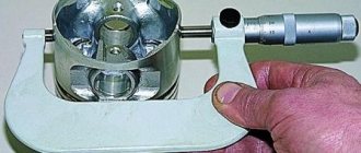
2. Using a bore gauge, measure the internal diameter of the cylinder at four levels (5, 12, 62 and 112 mm from the top edge of the cylinder) in two mutually perpendicular planes. Then, using a micrometer, measure the outer diameter of the piston (measurement must be in a plane perpendicular to the axis of the piston pin). Calculate the gap between the piston and cylinder. The standard gap should be 0.025-0.045 mm. Cylinder diameter is divided into five size classes.
Note
: The cylinder grade is stamped on the bottom surface of the cylinder block.
| Designation | Inner diameter, mm |
| A | 82.00-82.01 |
| B | 82.01-82.02 |
| C | 82.02-82.03 |
| D | 82.03-82.04 |
| E | 82.04-82.05 |
Installation of connecting rod and piston group
Note
: The following describes the operations that must be performed when replacing the connecting rod and piston group.
1. Select pistons according to size if maximum wear exceeds 0.15 mm. The pistons are divided into five classes (A, B, C, D, E) every 0.01 mm.
2. Select the piston pin according to the piston size. In order to simplify the selection of the piston pin, a mark is applied to the inside of the piston, the color of which corresponds to the pin size.
Formation of soot on the surface of SZ electrodes
Car enthusiasts often ask the question: “Why are there black deposits on the spark plugs and soot of a different shade forms?” It's simple - spark plugs are used under conditions of aggressive thermal and chemical influences. In particular, when burned, the working mixture forms a grayish coating on the electrodes and this is a sign of the correct operation of all systems. And black spark plugs, as well as white or red soot, are not only a warning about urgent replacement of spark plugs, but also about the advisability of promptly diagnosing the engine for failures and breakdowns.
The nature of the deposit will tell you about the causes of malfunctions
The shade of soot on the electrodes of the elements is a clear signal of what kind of failures in the power unit could lead to this. This is often due to the fact that sparking does not occur correctly, the composition of the fuel used or the temperature inside the combustion chamber does not meet the requirements. We will tell you why the candles turn black later.
Checking the condition of the power unit by carbon deposits
Automotive ignition elements remain a good diagnostic indicator if you need to identify problems with the ignition cycle of the fuel mixture. But you should not make an unambiguous conclusion about the condition of the power unit by inspecting the SZ after 25 or more than 1000 km of run. Diagnostics should be carried out exclusively on new products, after a short run-in (150-200 km).
Checking the SZ for the presence of black soot
To check for malfunctions in the power unit based on the soot formed, you need to:
- Supply new elements in accordance with technical specifications.
- Remove the SZ and look at the shade of soot that appears on them.
Travel 200 kilometers with them.
Troubleshooting carburetor problems
Regardless of whether an EMC is installed or not, the procedure for cleaning the idle fuel jet is the same.
- Unscrew the plug holder or EMC.
- Unscrew and remove the fuel jet XX.
- Clean the central channel of the jet.
In order to remove the XX jet from the radiator body, you will need a 13-size wrench, but depending on the design, a 14-size wrench can also be used. After turning the EMC, remove the nozzle. If the center hole is clogged, carefully clean it with a thin wire or blow it out with compressed air.
Once the fuel jet center channel is clean, reinstall it.
Screw in until it stops and tighten carefully with a wrench. Connect the “positive” wire to the power terminal of the EMC
To make it easier to work with the carburetor, it is necessary to remove the air filter. Turn on the ignition, first removing the power wire from the EMC terminal. Touch the power wire to the valve terminal. A distinct click indicates that power is coming to the EMC input. In this case, the cause of the malfunction should be sought in the jet or in the carburetor itself. The absence of a click indicates that the fault is in the solenoid valve or fuse. To check the valve, connect the “plus” of the car battery to the terminal of the EMC, and the “minus” to its body. If there is no click, the solenoid valve is faulty and must be replaced.
If power does not come to the EMC input, the reason may be a faulty wiring or the need to replace an 8A fuse. If you have a standard fuse box, then this part is installed in the 9th cell.
Installing the connecting rod and piston group
The connecting rod and piston group (CPG) must be installed as an assembly. It is not recommended to press the piston pin into the connecting rod head without special tools. This procedure is best left to professionals.
To install the ShPG, you need a steel mandrel in the shape of a ring. The height of the ring is 2-3 cm, the diameter of the hole is slightly larger than the diameter of the cylinder. The pistons must be mounted in such a way that the arrow on their bottom (the part adjacent to the valves) is turned towards the oil pump. The number of the connecting rod and piston must correspond to the number of the cylinder. Before installation, you need to separate the locks of the oil scraper and compression rings at an angle of 120 degrees.
Installation algorithm.
- Turn the block over.
- We wipe the cylinder walls and crankpins with a dry cloth.
- Thoroughly lubricate the cylinder walls, the side surfaces of the pistons and the inside of the mandrel with oil.
- We place the mandrel on the cylinder and insert the piston and connecting rod assembly through it. We push the piston into the cylinder using a round wooden stick (hammer handle).
- Place the liner in the connecting rod cover and lubricate it with oil.
- We lay the block on its side and install the connecting rod cap so that the cylinder number on it and on the connecting rod are on the same side. We secure the cover with nuts.
- In the same way we mount the remaining pistons and connecting rods. After this, turn the cylinder block upside down and tighten all 8 nuts securing the connecting rod caps.
If you don't have a mandrel, you can cut it yourself from a piece of thick-walled steel pipe.
Engine overhaul
Unstable engine operation, the occurrence of extraneous noise, knocking, high fuel consumption, and a decrease in power may indicate the need for a major engine overhaul. On a VAZ 2108, engine overhaul includes restoring the technical characteristics of the unit to the indicators indicated in the operating instructions. Overhaul of the VAZ 2108 engine is carried out after removal from the vehicle and complete disassembly of the unit.
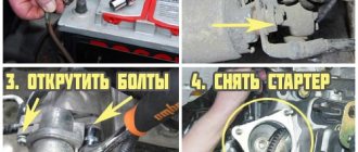
Removing the engine from the car
- The battery is removed.
- Oil and cooling fluid are drained from the engine crankcase from the system.
Tip: The engine must be removed together with the gearbox. You need to lower it down from the engine compartment. It is more convenient to carry out work on a lift.
- The bolts are unscrewed and the engine crankcase protection is removed.
- The exhaust pipe of the muffler is disconnected.
- The air filter is removed.
- The vacuum hose intended for the brake booster is disconnected from the inlet pipe of the device.
- The ground wire is disconnected from the clutch housing.
- The hoses are disconnected from the thermostat.
- The high-voltage wire is released from the distributor cover.
- The block with low-voltage wires is disconnected.
- The hose for supplying fuel from the fuel pump is released.
- The cable end attached to the clutch release lever is removed.
- The block with the wire is disconnected from the traction starter relay.
- The block with the wire is disconnected from the generator output.
- The wires are disconnected from the carburetor valve.
- The hose for return drainage from the fuel carburetor is removed from the clamp.
- The choke rod is released from its control lever.
- The air damper drive cable is disconnected.
- The clamp holding the accelerator drive cable is removed from the damper drive sector.
- The air spring for the throttle valve drive is removed. The drive cable is removed from the latter sector.
- The bracket holding the accelerator drive cable is disconnected from the valve cover.
- The sensor that controls the coolant temperature is released from the connection.
- The oil pressure sensor is turned off.
- The heater inlet and outlet hoses are disconnected.
- The drive rod is released from the joint tip to change gears.
- The speedometer turns off.
- The switches for the vehicle's reverse lights are disconnected on the gearbox.
- The right and left braces are moved to the sides so that they do not interfere with removing the engine from the car.
- The cotter pin is pulled out, securing the nut holding the ball joint of the steering linkage and the swing arm.
- The nut holding the steering rod ball joint is unscrewed.
- Using a special puller, the steering link joint pin is pressed out of the strut lever.
- The ball joint for the suspension arm is disconnected from the steering knuckle.
- Using a pry bar, the shank of the inner CV joint of the gearbox drive shaft is pressed out and moved to the side.
- Having secured the side gear from turning, the second CV joint is disconnected like the first.
- The engine clings to the frames and the hoist cables are pulled as shown in the photo.
Slinging a VAZ 2108 car engine
- The nuts securing the rear engine mount to the body are unscrewed.
- By slightly lifting the engine, remove the bolt holding the right front support of the unit.
- The left front support is released in the same way.
- The engine is lowered onto stands, the car is raised and the engine is pulled out from under it.
Tip: Before lowering the engine, make sure that all wires and hoses are disconnected from it.
Overhaul of the VAZ 21083 engine begins with disassembling it and drawing up a defect list. After a thorough examination of all parts and measurements of the dimensions of the mating parts, the stages of repair and its cost are determined. Parts that can be repaired are subject to restoration, those that have become unusable are replaced with new ones. According to the rules for the VAZ 2108, major repairs are carried out after 150,000 kilometers of the vehicle. Repairs begin with replacing piston rings and pistons and boring the cylinder block. The crankshaft journal is ground. A visual inspection of the starter, generator, and ignition distributor is carried out. In the cooling system, hoses, thermostat, drive belts and pump are replaced. The radiator is washed and cleaned.
Engine assembly
The engine begins to be assembled by installing the main bearings and crankshaft. Nowadays you can come across liners in different configurations, in the photo the liners are not very well equipped as there are no holes on the liner for the central crankshaft journal, and since this journal does not have a through hole, the lower liner will be starved of oil and this leads to faster wear of the crankshaft journal . So don’t be lazy and drill a couple of holes as shown in the photo below.
Photo. Correct installation of liners in the VAZ 21083 engine block.
Before installing the liners in the bed, carefully wipe the bed with a rag so that nothing gets under the liner; debris under the liner can lead to pinching of the crankshaft and poor heat transfer of the liner to the engine block. Install the half rings immediately as shown in the figure, lubricate the inserts with oil, and also lubricate the half rings inside with oil, then they will not fall out of their places.
Photo. The arrow shows the thrust half-rings of the VAZ 21083 engine
After installing the crankshaft into the block, be sure to check the longitudinal movement of the crankshaft, this can be done with a screwdriver as shown in the photo below, insert it from different sides, if there is movement of the crankshaft, then repair half rings are needed. Here you can already select one repair and the other standard, or lightly grind the half ring on a stone or sandpaper spread on a flat surface. Try to ensure that there is no longitudinal movement of the crankshaft; if there is longitudinal movement, the half rings may fall out during engine operation.
Photo. Checking the longitudinal movement of the crankshaft.
Now you need to put the crankshaft cushions in their places, each cushion must return to its place, you cannot install a cushion from another engine as it will be slightly different in the gap and can either clamp or give way. The photo below shows how to install the pillow correctly, note that the lock of the liner is placed next to the lock of another liner, the photo shows the installation of the third pillow with drilled holes. It doesn’t matter whether the holes are beautifully drilled or not, what is important is that oil will flow through them to the crankshaft journal.
Photo. Correct installation of the crankshaft cushion.
Immediately place all the cushions on the crankshaft but do not tighten, tighten the bolts. Now start tightening one cushion at a time, I always start with the third one, tighten it until the crankshaft is tight, turn it with a wrench as shown in the photo below. And so after each tightened pillow, try to rotate the crankshaft. You need to tighten the pillows well, but do not overdo it, as you can break the bolts. You can read more about the crankshaft in the article Repair of the crankshaft (crankshaft).
Photo. Tightening the crankshaft cushions.
After installing the crankshaft, we begin installing the pistons. The photo below shows how the piston should be installed correctly in the cylinder. You can read more in the article Changing pistons on a VAZ 08-09.
Photo. Correct installation of the piston in the block, the arrow shows the liner lock on the connecting rod.
Before installing the piston into the cylinder, be sure to lubricate the piston rings with oil and do not forget to lubricate the connecting rod bearings with oil.
Photo. Installing the piston into the cylinder using a homemade clamp, which I grasp one ring at a time, insert the oil scraper, and insert the next one with a light blow of the hand.
The pistons and connecting rods are in place, we install the rear cover, but do not forget to replace the old oil seal with a new one, I do not put a gasket under this cover, I apply sealant.
Photo. Rear engine cover of VAZ 2108.
Before installing the flywheel, use a chisel to make a clearer groove along the factory mark, since the factory mark is very thin and can be difficult to find on the flywheel when it is in the engine.
Photo. Mark on the flywheel of the VAZ 21083 engine
The correct way to install the flywheel is to place the fourth piston at the very top as shown in the photo, the mark should be at the top.
Photo. Correctly installed flywheel on a VAZ 21083 engine
Be sure to lubricate the bolt threads with sealant when tightening the flywheel, since in the crankshaft there are through threads that are not coated with sealant and a bolt that is not coated with sealant can leak oil into the clutch disc.
Photo. The bolt is coated with sealant when tightening the flywheel.
To easily and firmly tighten the flywheel, you can use the method shown in the photo below. Block the connecting rod with the pipe and tighten the bolts with the head.
Photo. Flywheel tightening.
After installing the flywheel, you need to install the clutch disc correctly; if you put it in the opposite direction, the clutch will not work. In the photo below you see the clutch disc and basket, the arrow shows the protruding washer of the clutch disc, it should fit into the basket. As shown in the photo, this is how it should be installed; the input shaft from the classic box is ideal as a clutch disk centering mandrel.
Photo. Correct installation of the clutch disc.
Photo. A twisted basket with a centering shaft, after which this shaft is pulled out, the shaft gives precise alignment of the clutch disc, without a centering shaft it is very difficult to correctly center the clutch disc. And this may prevent you from putting the engine on the box, since the box shaft will rest against the clutch disc.
Photo. Shaft in the clutch disc.
Now you can install the front cover (oil pump), do not forget to replace the oil seal with a new one, touch the oil pump to the crankshaft groove. I don’t put a gasket under this cover; I use sealants. Install the timing belt drive key and gear. Screw on the front crankshaft pulley.
Photo. Tightening the front crankshaft pulley.
Before installing the oil receiver, be sure to coat the tip of the tube with sealant, this will prevent air from leaking into the oil pump; if this is not done, the old rubber gasket will poison the air, which will lead to poor oil pressure.
Checking and adjusting the carburetor
One of them can be the carburetor itself, more precisely the float chamber, as well as the channels through which fuel enters it. If there is not enough gasoline in the chamber, or it simply is not pumped into it, then you should check the strainer installed under the plug (Figure 2). The check sequence is as follows: unscrew the strainer plug (2), remove the element itself (3) and wash and blow it. Then we install everything back and check its functionality.
If upon removal it is revealed that the filter is not clogged, then the reason for the non-flow of gasoline may be the sticking of the needle valve (1) installed in the float chamber cover, or the float itself (4) touching the body.
Rice. 2. Carburetor float chamber:
1 – needle valve; 2 – filter plug; 3 – mesh filter element; 4 – float.
Often during testing it turns out that gasoline is entering the chamber, but its quantity is not enough. To set the required level by bending the adjusting tongue (3), which is shown in Figure 3. When bending the tongue, you will also have to bend the float stop (2), which will allow you to adjust the needle stroke (4). After adjustment work, you should make sure that the float moves without any jamming. If it is determined that the float is full of gasoline, this indicates its breakdown, so it is better to replace the damaged element. If you don’t have a new element at hand, you can temporarily use the old one, after sealing it with epoxy glue.
Rice. 3. Adjusting the fuel level of carburetors on GAZ (a), “Zaporozhets” (b), “Moskvich” (c), VAZ “Classic” (d), ZAZ “Tavria”, VAZ-2108-09, AZLK “Aleko” ( d):
1 – float; 2 – float limiter; 3 – float tongue; 4 – needle.
If, as a result of the check, it is established that there is gasoline in the float chamber, and in sufficient quantity, but the engine “does not want” to start, then the reason for this may be clogged jets or fuel channels. In this case, the channels and nozzles should be flushed with gasoline, followed by blowing with compressed air. To do this, you will have to remove the float chamber cover from the carburetor.
If it is determined that the blockage of the jets is serious (a layer of resinous deposits has formed), then the blockage can be removed using a wooden stick, which must first be dipped in acetone. Cleaning the channels and jets is not allowed with any metal objects or wire.
It happens that the stream of gasoline from the supply line (11), shown in Figure 4, is very weak and uneven, and there are also air bubbles in it, then this is a signal of clogging of the fuel pipes or a malfunction of the fuel pump itself.
Rice. 4. Auto power system:
1 – air filter housing; 2 – carburetor; 3 – gas tank; 4 – tank ventilation tube; 5 – tank lid seal; 6 – cover; 7 – tank mounting clamp; 8.11 – fuel lines; 9 – manual pumping lever; 10 – fuel pump; 12 – coolant supply fitting for carburetor heating; 13 – intake manifold; 14 – carburetor mounting studs; I and IV are places where fuel lines are disconnected when troubleshooting problems in the power system.
Do-it-yourself engine repair VAZ 2109
RepairDo-it-yourself engine repair VAZ 2109
THIS IS INTERESTING: Misfire in cylinder 1 of VAZ 2114
Do-it-yourself VAZ 2109 engine repair
Author of the article June 02, 2014
If suddenly the fuel consumption of a VAZ 2109 sharply increases, knocking noises appear, power is lost, and black smoke is released from the exhaust pipe, most likely the engine life has been exhausted. But you shouldn’t despair, repairing a VAZ 2109 engine is not expensive, and besides, you can even do it yourself. To do this, you need to know how the engine works, and have some money to buy spare parts.
Even a beginner can repair the engine of a VAZ 2109 only if it is an old carburetor engine. If it is an injector, then much more skills are required in understanding the principle of its operation.
The VAZ 2109 has an in-line, four-piston, 8-valve engine. The principle of its operation is very simple, it is only important to adhere to some rules when assembling.
Before deciding to remove and repair the VAZ 2109 engine, you need to determine whether it needs it. First of all, you need to measure the compression; if it is low, the piston needs to be changed. However, low compression may be the result of burnt-out valves or a broken cylinder head gasket.
You also need to look at the oil pressure; if it is low, then the bearings are worn out or the oil pump has failed.
Engine repair
The heaviest load in the VAZ 2109 engine is placed on such components as piston and plain bearings. When the piston wears out, compression drops, and oil begins to pass into the combustion chamber, so its consumption increases. The piston rings wear out first, so sometimes the entire piston repair consists of replacing them. If the piston is very worn, shells or grooves are visible on the liners and pistons, the piston is replaced.
As for the plain bearings, with high mileage and loads, the crankshaft journals wear out. In this case, either the crankshaft is changed, or its necks are sharpened to a smaller size. After this, repair size liners are used.
The next important system of the VAZ 2109 engine is the gas distribution system. When repairing, the cylinder head must be disassembled and the valves removed. They must first be numbered to be installed back in the same order.
The valves may have carbon deposits, chips, or shells. If there are any, the valve is changed. To ensure that the valve closes tightly, it is ground in a rotating motion using special grinding pastes.
Some craftsmen do this using a drill and a small piece of hose.
Attachments VAZ 2109
When repairing a VAZ 2109 engine, the serviceability of all other additional devices is also diagnosed. This includes the carburetor, generator, starter, fuel and oil pump, and so on. Most often, the fuel pump and starter break down on the VAZ 2109.
Since the fuel pump is relatively inexpensive, during a complete overhaul it is best to replace it with a new one. As for the starter, it can be repaired quite successfully.
In it, only bushings and brushes can be replaced, which can be purchased at any auto store.
As for the oil pump, it also needs to be disassembled and inspected. If necessary, you need to change the gasket.
When repairing an engine on a VAZ 2109, it is mandatory to disassemble and adjust the carburetor. In principle, there is nothing to break here.
All you need to do is disassemble the carburetor, wash it, blow it out and put it back together in exactly the reverse order, without mixing up the jets. Before assembly, you need to set the correct gasoline level in the float chamber.
If the carburetor is already very old, it is best to purchase a repair kit to replace the gasket, accelerator pump diaphragm and jets.
In general, engine repair on a VAZ 2109 is quite simple, you just need to know exactly to what point to tighten the nuts on the plain bearings. For these purposes, it is best to purchase a torque wrench. Repairs must be carried out in perfect cleanliness, and all nuts, bolts and bearing caps must be placed clearly in their original places.
“Likes” on social media networks:
VAZ 2108 engine repair
In the process of repairing a VAZ 2108 engine, you should work with the following elements:
- Piston. We clean the piston head from carbon deposits. Using wire, you should make a hole into which the oil will drain. If necessary, the inter-groove gaps and rings are adjusted. Using a piston ring, which is inserted into a mandrel, the gaps that exist in the ring locks are measured. The permissible gap is from 0.015 to 0.045 mm. A gap of 0.25 mm is also acceptable. If the indicator exceeds 0.25 mm, the cylinders should be bored and pistons of the required size should be installed.
- Connecting rod - piston assembly. When replacing the corresponding parts of the connecting rod and piston assembly, the pistons should be sorted according to their intended purpose for the cylinders. We also replace piston rings that have become unusable, as well as the oil scraper ring expander. In a situation where it is noted that the retaining rings are in poor condition, they need to be replaced. The connecting rods should be replaced if burrs or scratches are found on the surface of the upper head, or if they have turned. It is necessary to replace the connecting rod if there is some swaying of the piston pin and play is observed.
- Crankshaft. The crankshaft should be replaced if scratches are found on the surfaces where the oil seals operate. It is imperative to replace the half rings if nicks, scratches, or risks are found on their surface. During the repair process, the main and connecting rod bearings are checked. If burrs or cracks are present, new liners should be installed. It is prohibited to customize them.
- Cylinder block. The surface of the cylinder block should be thoroughly cleaned of gasket residues. If cracks are detected, the unit with gearbox covers must be replaced. To check the tightness, plug the water deposit and pour coolant into the jacket. If a leak appears, the cylinder block must be replaced. If any burrs, scratches are found, or a new block is installed, the cylinders should be bored. If the size of the defect exceeds 0.8 mm, then there is no point in repairing the block. It needs to be replaced. During the repair process, cylinder wear is monitored and their diameters are carefully measured. After repair, the engine should work clearly and smoothly (example in the video).