Subscribe to topic
Notification by e-mail about replies to a topic during your absence from the forum.
Subscribe to this forum
Notification by e-mail about new topics on the forum during your absence from the forum.
Download/Print theme
Download the theme in various formats or view a printable version of the theme.
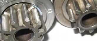
Every car has a speed control system that allows the driver to always know at what speed limit he is traveling. One of the main elements of such a system is the speed sensor (DS) on the VAZ 2110. You can learn more about this device, its purpose, problems, and diagnostics from the video below.
Purpose of a speed sensor in a car
The VAZ 2110 speed sensor is responsible for the correct supply of gasoline. It also allows you to set the ignition timing; in addition, the device monitors the quality of the air-fuel mixture.
Speed controller for VAZ 2110
The regulator collects all the necessary information for the injector - engine speed, driving speed, detonation data, etc. — after which it transmits impulses to the ECU. After transmission, the control unit checks all received information, as a result of which it makes changes to the functioning of the injector.
Signs of trouble
If the odometer stops working normally, and the speedometer gives incorrect information regarding the mileage traveled and speed, this indicates a malfunction. This may be a problem with both the VAZ 2110 speed sensor and the device drive. It is possible that the problems are related to the electrical wiring. Also, in practice, problems often occur caused by the pinout of the speed sensor, which can be confused or the connector itself is inoperable. In the latter case, the problem may be due to poor contacts.
Among other things, a sign of a malfunctioning regulator may be that the car stalls at idle. Of course, there can be many reasons why a car stalls. If the speedometer located on the instrument panel produces incorrect data, the Check Engine indicator on the dashboard should light up. If the DC fails, you will immediately notice a lighted check on the dashboard.
Do-it-yourself tachograph installation
Resolution No. 720 of September 10, 2009 states that from January 23, 2011, all vehicles belonging to categories N2 and N3, as well as M2 and M3 and carrying out commercial passenger and cargo transportation must be equipped with technical devices that allow monitoring compliance by drivers modes of movement, work and rest.
Thus, Russian legislation obliges the installation of tachographs on vehicles belonging to categories C, D and E, except for vehicles traveling along routes whose length is no more than 50 kilometers (there are other regime rules there).
On vehicles manufactured after 2006, places are provided to accommodate tachographs and therefore installation takes no more than 2.5 hours, which depends on the location of the speed sensor, the length of the wire leading to the cabin, and whether the speed sensor and speedometer will need to be replaced. This instruction will be useful for those who install a tachograph with their own hands or for novice craftsmen. We will need the following equipment to install the tachograph:
- the device itself;
- the wire;
- connection chips;
- speed sensor and speedometer (if necessary);
- set of keys and sockets;
- control;
- tester.
Tachograph installation rules
There is a standard 1din space allocated for the device in the cabin. The tachograph must be installed so that it is clearly visible to the driver during the trip, and is also easily accessible for inspection. If there is no provision for mounting the sensor, then installing it will require all your ingenuity. Regarding the sensor that needs to be purchased, it is better to consult with a specialist in this particular case.
Satellite antennas must be installed so that they can “see” the sky. Installation under metal surfaces is prohibited. It is possible to place the antennas on the roof of the cabin, but in this case I would recommend coating everything with sealant.
The wire going from the sender to the tachograph must be laid so that its integrity can be checked visually. During installation, the wire must not be cut - there should be no bottlenecks along the laying route. Since the wires are armored, the points of change of direction must have a large radius. True, the experience of their operation indicates poor resistance to reagents used in a number of Russian regions, so it is better to lay the wires in places that are difficult to reach for salt.
If you have to disconnect the speedometer sensor when installing the tachograph sensor, you will need to run wires from the device to the speedometer. It should be taken into account that it is forbidden to crash into the speedometer sensor - the signal must be taken from another tachograph connector.
Since the sensors differ in signal characteristics and in their number relative to the distance traveled, the speedometer must also be calibrated by a specialist.
Installation process
The whole process can be divided into several stages:
- inspecting the car to determine whether it is necessary to replace the speed sensor and speedometer;
- selection and replacement (if necessary) of the speed sensor and speedometer;
- connecting the tachograph wires to the speed sensor and speedometer;
- examination;
- calibration and activation of the CIPF unit (performed in a specialized center).
Now about each point in more detail.
Speed sensor and speedometer
When inspecting the vehicle, you need to pay attention to the speed sensor and speedometer. If the speedometer is mechanical with a cable, then it definitely needs to be replaced, and you will also need to install a speed sensor. It is possible to use a pass-through sensor to keep the old speedometer, but this option is only a last resort. When installing a tachograph on a Kamaz , you may encounter speed sensors in the form of a small generator, which, depending on the speed, changes the voltage that is supplied to the speedometer, in which a motor is installed, the rotation speed of which directly depends on the voltage. When installing a MAZ tachograph, we may need an adapter for installing a new speed sensor; it can be picked up in a store or machined (for special extreme sports enthusiasts).
Which speedometer to install is up to you, it all depends on your budget and the size of the hole on the instrument panel. You can find out more about the models of speedometers and speed sensors in the catalog on our website. Let's return to the installation, if you need to change the speedometer and sensor, we carry out work to replace them. They are carried out very simply; just above are recommendations for laying a new cable from the box to the speedometer. The speed sensor is usually simply unscrewed, and a new one is screwed in to replace it.
Now we connect the device to the on-board network
The tachograph connection diagram is usually different, this is caused by the huge number of not only car brands, but also their modifications. As a rule, the main wires to be connected during installation are: - power supply +1224 Volts. It is taken from 1 power circuit or pulled from the battery; - weight. It is connected to the housing or pulled from the terminal block with ground. if there is no mass on the vehicle body (for example, MAN cars); — ignition. As a rule, it is located on the ignition switch (toggle switch) or under the dashboard, designated as ACC; — turning on the low beam headlights. Designed to automatically adjust the brightness of the tachograph display, taken from the fuse box in which the fuse is from the light or from the wire to the headlights under the dashboard; — power supply for the speed sensor. Power goes from the tachograph to the sensor. Everything is simple here, according to the diagram on the sensor we apply a plus; — weight of the speed sensor is the same; — signal from the speed sensor. We simply connect from the sensor directly to the connector; — output to the speedometer. Connected for the speedometer to work. The connection is made from the tachograph, and not from the speed sensor. Twists “all in a bunch” are not allowed! — additional equipment as necessary (fuel level sensors, temperature sensors and additional equipment).
Diagnostics of DS on VAZ 2110
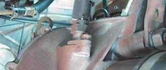
Location of the regulator in the engine compartment
How to check the speed sensor on a VAZ 2110 on your own? First of all, for this you need to know where the DS should be located, after which its drive is diagnosed. In accordance with the connection diagram, on the tenth VAZ models the regulator is located in the engine compartment, not far from the exhaust manifold. As practice shows, connection wires can rub against a heated collector, causing them to melt.
As a result, a short circuit occurs. As a rule, this problem can be solved by insulating the wires and fixing them so that they do not come into contact with the collector. Another diagnostic option would be to check for a broken cable. This reason is one of the most likely. If the cable is in order and no damage was detected during the process, then the problem lies in the controller itself or its drive.
Preparing for replacement
In order for the procedure for replacing the controller on the tenth VAZ model to proceed correctly and to obtain the expected result, namely the normal functioning of the speedometer, you should be properly prepared for this process.
Firstly, on a VAZ 2110, replacing the DC means purchasing a new controller. When purchasing a new regulator, you need to pay attention to the fact that each connector located in the block design has certain symbols. It should contain the symbols “-”, “A” and “+”, not numbers. In principle, in this case there is not much difference between these options; when connecting the connector you will have fewer problems with pinout. If you have never encountered a process like this, this pinout will allow you to complete it correctly.
Controller connector pinout
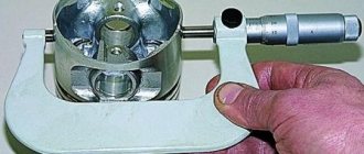
One more, no less important nuance. You need to buy a device that is equipped with a metal rod. This rod will last at least six months, which cannot be said about regulators with plastic rods. In addition, when purchasing, you must check whether the rod rotates or not. It should not rotate, there should be no play on this element, and it should also be equipped with a washer.
DIY repair and replacement
If you decide to replace the device yourself, familiarize yourself with the removal and replacement procedure.
The controller is dismantled as follows:
- First you need to de-energize the vehicle's on-board network; to do this, disconnect the negative cable from the battery.
- Next, disconnect the wiring connector from the controller itself. At this stage, it is important to remember what pinout these elements have.
- The controller itself can be unscrewed by hand. If you can’t do this on your own, try using a 21 or 22 wrench. In this case, the regulator may have certain differences in design.
- Also immediately check how well the drive functions. After the regulator is removed, it is necessary to unscrew the nut that secures the drive to the gearbox. The dismantling procedure must be done very carefully, because if you accidentally drop the rod into the transmission, the box will need to be removed and disassembled. As for the new drive, it is equipped with a rubber seal. Before installation, it must be lubricated with transmission fluid. Below is a video that will allow you to more clearly understand the procedure for replacing the controller (the author of the video is Auto News).
All new components must be installed in reverse order. Again, in this case the wiring pinout plays a big role. Inside the block itself you can see how the pinout is indicated. Using a tester with the ignition activated, it is necessary to determine which connector the drive should be connected to.
If the multimeter shows “-” and the drive was connected to the positive connector, this indicates that the polarity needs to be changed. Next, the drive is diagnosed, and you should also check the operation of the speedometer while driving or with the front of the vehicle raised (so that the wheels are suspended).
If you doubt that you can carry out the entire procedure yourself and change the controller correctly, we advise you to seek help from specialists. In principle, this process is not particularly complicated, so the cost of the replacement service will not be particularly high. For installation, it is better to use a higher-quality regulator so that in the future you do not face the need to repair and replace it.
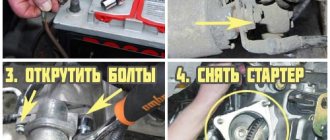
Replacement
The process of replacing a diesel engine is very simple, and even the most uninitiated car owner can cope with it.
Required tools:
- key to 21;
- key to 10;
- crosshead screwdriver.
Execution procedure for VAZ 2110 with drive sensors.
1.Raise the hood, disconnect the “-” terminal on the battery.
2. Determine the location of the sensor. For both old and new models, it is located on the back of the engine at the top of the gearbox.
3.If necessary, use a screwdriver to loosen the corrugation clamp, remove it, and move it aside.
4.Squeezing the antennae on the sensor connector, disconnect
5.Use your hands or using a 21 wrench to unscrew the sensor.
6.Using a 10mm wrench, unscrew the nut securing the DS drive and carefully remove it.
7.If the drive is in order, you can leave the old one, but if it has traces of mechanical stress, we replace it.
8. Having installed the drive, install a new sensor by screwing it clockwise.
9.Connect the connector, connect the corrugation, and the negative terminal.
10.Check.
Changing the electronic sensor
1.De-energize the vehicle's on-board circuit.
2. Using a screwdriver, loosen the corrugation clamp and remove it.
3. Disconnect the wires from the DC by moving the latch.
4.Using a 10mm wrench, unscrew the sensor mounting nut.
5.Remove the old sensor, install the new one, tighten the nut.
6. Connect the corrugation.
7.Connect the ground terminal.
Video “Step-by-step instructions for replacing DS on injection VAZ 2110”
Detailed and visual instructions for replacing the controller on domestic “tens” are given below (the author of the video is the channel In Sandro’s Garage).
1200 rub. for the photo report
We pay for photo reports on car repairs. Earnings from 10,000 rubles/month.
Write:
If the engine stalls while idling , then most likely you will need to check several sensors (mass air flow sensor, air sensing sensor, speed control valve, air pressure sensor) in order to determine the culprit. Previously we looked at verification methods:
Now, checking the speed sensor yourself will be added to this list.
If this sensor malfunctions, it transmits erroneous data, which leads to disruption of not only the engine, but also other components of the car. The vehicle speed meter (VSM) sends signals to the sensor, which controls the operation of the engine at idle speed , and also, using PPX, controls the air flow bypassing the throttle valve. The higher the speed of the car, the higher the frequency of these signals.
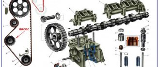
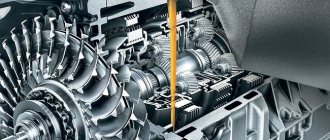
Operating principle of the speed sensor
The speed sensor design of most modern cars is based on the Hall effect. During its operation, it transmits pulse-frequency signals to the vehicle's ECU at short intervals. In particular, over one kilometer of travel, the sensor transmits about 6,000 signals. In this case, the frequency of impulse transmission is directly proportional to the speed of movement. Based on the frequency of signals received, the electronic control unit automatically calculates the speed of the machine. It contains a program for this purpose.
The speed sensor itself is located next to the gearbox, in particular, in the speedometer drive mechanism. The exact location differs between different car brands.
Speed sensor replacement: useful details about the service
The speed sensor has long become an integral part of every modern car (regardless of its make and model). Despite its more than modest dimensions, this device plays an extremely important role in the stable operation of the vehicle. Its malfunction not only increases the risk of an emergency on the road with your participation, but can also lead to, say, engine stalling or loss of dynamics during acceleration. Therefore, the speed sensor must be replaced as soon as possible after a malfunction is detected.
How to determine that the speed sensor is not working
You should immediately pay attention to such signs of malfunction as:
- no idle stability;
- the speedometer does not function correctly or does not function at all;
- increased fuel consumption;
- reduced engine thrust.
Also, the on-board computer may display an error about the absence of signals on the DSA. Naturally, if BC is installed on the machine.
Speed sensor location
Most often, the malfunction is caused by a broken circuit, so first of all, you need to diagnose its integrity. First you need to disconnect the power and inspect the contacts for oxidation and dirt. If it is, then you need to clean the contacts and apply Litol.
often break near the plug , because this is where they bend and the insulation can fray. You also need to check the resistance in the grounding circuit, which should be 1 ohm. If the problem has not been resolved, then it is worth checking the speed sensor for functionality. Now the question arises: how to check the speed sensor?
Checking the speed sensor
First you need to find out whether there is grounding and 12 V voltage in the contacts. These contacts are wired, and the contact with pulse signals is tested by torsion.
Method 1 (check with a voltmeter)
- We remove the speed sensor.
- We use a voltmeter. Let's find out which terminal is responsible for what. We connect the incoming contact of the voltmeter to the terminal that outputs pulse signals. We ground the second contact of the voltmeter to the engine or machine body.
- By rotating the speed sensor, we determine whether there are signals in the operating cycle and measure the output voltage of the sensor. To do this, you can put a piece of tube on the sensor axis (twist at a speed of 3-5 km/h). The faster you rotate the sensor, the higher the voltage and frequency in the voltmeter should be.
Method 2 (without removing from the car)
- Place the car on a jack so that one wheel does not touch the ground.
- We connect the contacts of the sensor with a voltmeter.
- We rotate the wheel and diagnose whether voltage appears - if there is voltage and frequency in Hz, then the speed sensor is working.
Method 3 (check with a control or light bulb)
- Disconnect the pulse wire from the sensor.
- Using the control, we look for “+” and “–” (after turning on the ignition ).
- We hang one wheel as in the previous method.
- We connect the control wire to the “Signal” wire and rotate the wheel with our hands. If “-” lights up on the control panel, then the speed sensor is working.
Checking the DS with a tester
Why does the speed sensor fail?
Spare parts for Mazda 2
Spark plug
2 hatchback (DL, DJ) (11.14 - )
Spare parts for Rover 100
Rear left wing 100 hatchback (METRO) (XP) (11.90 - 12.98)
Like almost all electronic components of a car, the sensor suffers primarily from oxidation of contacts and damage to the integrity of the wiring. Often the problem can be identified during a visual inspection, although it is worth using a tester to be sure. Each of the contacts must be disconnected and checked. Oxidized and simply dirty contacts must be cleaned and coated with a special lubricant . Another weak point of the most common car speed detection systems is the speedometer cable. Over time, it breaks in several places at once, which ultimately affects the correct determination of the vehicle’s speed. The old cable needs to be changed and coated with machine oil before installation, just in case.
Oddly enough, the most common and seemingly reliable speed detection systems do not tolerate driving with sudden increases in speed. Because of this, the integrity of the plastic tail in the sensor is quickly compromised. The cable also begins to delaminate and crack. As mentioned above, the cable needs to be lubricated. The tightness of the fastening of the plastic tail must be controlled - it should be high, which will prevent subsequent loosening of the fastening socket.
Checking the induction DS
The signal that comes from the rotation of the wheels essentially resembles the oscillation of a wave impulse. Therefore, the voltage changes depending on the rotation speed. Everything happens in the same way as with the crankshaft angle sensor.
Subscribe
to our channel in
Index.Zen
Even more useful tips in a convenient format
If the sensor is working properly and the gear is not leaking, then there may be no power to the sensor or there is a break/short somewhere in its wiring. In addition, the ECU and ABS are involved in the readings on the tidy. The wire from the ECU to the instrument panel or from the ABS may have been lost (you should call the wire from the speedometer to the ABS block). It is possible that the device is faulty.
Good day everyone, I have such a problem that the speedometer and odometer do not work. My car is a Hyundai Santa Fe 2 2007. I checked the speed sensor drive gear, everything is ok, I don’t know how to ring or check the sensor itself. The workers checked the inductive sensors on the box by eliminating everything, the check light came on, I don’t know what else could be the reason, since you drive with a scanner, the speed shows “0” on the speedometer, maybe someone has someone who can tell me.
Guys, good afternoon everyone! Please tell me! I have a Lada 14 and just recently the speed began to fluctuate, it almost stalls, it does not work evenly. Diagnostics showed a camshaft sensor, they replaced the sensor with a new one, but there was no result. By the way, the speedometer and tachometer do not work. What could be the reason?
Thank you, detailed article!
And it will be even more clear how to check the speed sensor if you watch the video of the HF channel: https://youtu.be/qiDmZLUuTMI
Thank you for a very clear and accessible description of checking the speed sensor yourself. Thanks to the instructions, I was able to do it myself. It turned out to be really dying.
Good afternoon Subaru Outback has a 2007. The check lights up. The error code reveals P0500 - circuit speed sensor. But there are three sensors there. The question is how to determine which of them does not work? Or how else can I check?
The reason is not always only in the speed sensor (this behavior can also appear when the contacts in its connector oxidize), although if it starts to lie, then this is precisely the problem. Perhaps the problem lies in the device itself, then you have to disassemble it and check the arrow drive mechanism. On cars with a cable drive, such a malfunction is often hidden either in old oil on the gears, or in a worn square at the end of the cable, or the lubrication of that same cable helps.
where is the sensor located, signs of failure
All modern cars are equipped with a speed sensor. Its task is to measure the speed of the car and transmit this information to the electronic control unit. Based on the received signals from the sensor, the idle speed, the amount of air supplied and other parameters that directly affect engine operation are adjusted. The higher the vehicle speed, the higher the frequency of the transmitted signals.
Symptoms of speed sensor failure
The driver must react in time if the speed sensor fails by replacing it with a new one. If this is not done, the engine will not perform optimally and its components will suffer additional wear and tear. The following symptoms indicate a speed sensor failure:
- The engine is unstable at idle;
- In the usual operating mode, the engine began to consume more fuel;
- The speedometer erroneously displays information about the vehicle's speed. If the sensor is completely out of order, it may not report it at all;
- The car began to accelerate worse.
In many modern cars, error information appears on the on-board computer when the speed sensor fails. The Check Engine light may also come on.
Why does the speed sensor not work?
The most common cause of speed sensor failure is a broken circuit. Before checking the sensor itself, you need to ensure the integrity of the circuit, for which:
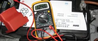
- The resistance in the grounding circuit is checked using a multimeter (switched to resistance measurement mode - Ohm). The resistance should be around 1 ohm, but it may vary on different car models, so it is recommended to check the exact values in the car manual;
- Disconnect the contacts and check them for oxidation and clogging. If the contacts are oxidized, clean them and apply Litol.
If the problem cannot be resolved by checking the circuit and contacts, you must proceed directly to diagnosing the sensor.
Please note: If you do not know where the speed sensor is located on your car, you can use a vehicle maintenance book or try looking for it on the gearbox. Most often it is located on the speedometer drive mechanism.
How to check the speed sensor
There are several types of speed sensors: Hall effect, reed and induction. Most cars, including Russian-made cars, have a Hall effect speed sensor installed.
How to test a Hall effect speed sensor
The speed sensor, whose operation is based on the Hall effect, has three contacts: ground, pulse signal and voltage. Such a sensor can be checked in three ways.
First way
- It is necessary to remove the speed sensor located on the gearbox from the vehicle;
- Next, you will need to use a multimeter switched to voltmeter mode to determine which of the contacts is responsible for what. Among the contacts, you need to find the one that produces a pulse signal. You need to connect the plus of the multimeter to it, and set the minus to the “ground”, which in this case can be the car body;
- With the multimeter connected, slowly start rotating the probe. Monitor the voltmeter readings. The higher the rotation speed, the higher the voltage should be. To make rotation more convenient, it is recommended to put a small piece of tube on the sensor axis.
Second way
- The speed sensor must be connected. For testing, you will need to lift one wheel of the car so that it does not touch the surface and can be rotated freely;
- We connect the multimeter in voltage measurement mode to the sensor contacts;
- Spin the wheel and evaluate the results. If the voltage and frequency change, this indicates that the sensor is working.
Third way
- To check, you will need to get a control light and turn on the ignition;
- Next, you need to lift one wheel of the car so that it can be rotated freely;
- We connect one wire to the battery positive, and the second to the signal contact on the sensor;
- We begin to spin the wheel. If the light blinks during rotation, it means the sensor is working.
What is the difference between induction and reed speed sensors?
The difference between an inductive speed sensor is the signal received when the wheels rotate. This signal resembles oscillations of a wave pulse, and the voltage changes depending on the rotation speed. The principle is similar to the operation of the crankshaft angle sensor.
As for the reed sensor, it transmits signals by means of rectangular pulses. The cycle is at a level of 40 to 60%, and switching occurs from 0 to 5 Volts or up to a battery voltage of 12 Volts.