GAZ-53 car engine repair
Sometimes a car breaks down, requiring restoration measures. One of these procedures is the repair of the GAZ 53 engine, which has long expired its warranty period. Without cars, our lives would not only be less intense, but also more boring. In addition, cargo transportation is one of the priority tasks, which is carried out using vehicles. A prominent representative of the domestic automobile industry is the GAZ 53, which is well known to each of us and is used for various types of cargo transportation.
This is what a classic GAZ 53 truck looks like
Cost of repair and maintenance of GAZ in Moscow
| Engine repair | Cost of repairs without spare parts including VAT, rub. | Cost of repairs including spare parts including VAT, rub. | Deadline | |
| Engine GAZ-53.66 | 30000 | 68000 | from 3 days | Sign up |
We serve more than 60 clients monthly. They trust us because AggregatAvto:
Reliable service provider, participant in government procurement
Official guarantee for work – 185 days
Professional equipment
Experienced service staff
No downtime
Convenience of payments
Engine operation and typical malfunctions
At the time of its creation, the legendary GAZ 53 car was equipped with two engine options with many modifications. The first of them was the 6-cylinder GAZ 11, which did not find its widespread note in this car model. In turn, the second version of the ZMZ 53 engine, with a volume of 4.25 liters, was installed much more times. Therefore, today the GAZ 53 engine is often exactly the ZMZ 53. This engine is a kind of standard for the reliability and durability of a car engine.
Engine ZMZ 53 for car Gas 53
- knocking of connecting rod bearings;
- burnout of exhaust valves;
- increased fuel and oil consumption;
- abrasion of piston rings;
- knocking of the upper bushings or pistons;
- burnout of cylinder block gaskets.
It is these problems that most often lead to engine failure, which can cause it to stop completely. Almost all of them are associated with violations of the operation of the unit. Thus, abrasion of the piston rings and the appearance of knocking in the connecting rod bearings are the result of neglecting the vehicle’s operating instructions.
In turn, burnout of various valves and gaskets is a direct consequence of system overheating, and an increase in oil consumption occurs as a result of ignoring preventive measures.
Preventive measures for the ZMZ 53 engine
Preventive maintenance of the ZMZ 53 engine is a guarantee of maintaining its optimal functionality and is designed to maintain the operation of the device at the proper level.
In addition, similar measures make it possible to promptly determine the formation of any serious damage to the motor and eliminate them at the lowest cost.
That is why these procedures are of great importance and help prevent the formation of minor malfunctions, the list of which was given above. In general, maintenance of the GAZ 53 engine consists of the following activities:
- replacing lubricant;
- tightening of cylinder heads;
- checking the exhaust manifold fastenings;
- control of the amount of coolant;
- adjustment of valves;
- checking the oil level in the system.
Timely implementation of all the above procedures can serve as the key to the successful operation of a car engine and guarantee its optimal functionality. Machine maintenance has its own subtleties that must be taken into account.
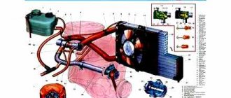
Engine lubrication system Gas 53
ZMZ 53 engine malfunctions
For an engine of the second half of the 20th century, the ZMZ-53 has a good service life - the average mileage before major repairs is about 200 thousand km. Of course, a lot depends on the operating conditions - if the car is constantly overloaded or operated on roads with long climbs, the service life of the engine is noticeably reduced. The Zavolzhsky motor is unpretentious and can operate for quite a long time in difficult conditions, but then, naturally, it needs repair.
Although the internal combustion engine is quite durable, it has its drawbacks, characteristic “sores”. The main diseases of the “Gazonovsky” engine:
- oil leak from the rear main oil seal;
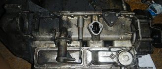
- warping of the “spider” (intake manifold);
- increased oil loss (consumption through piston rings);
- low oil pressure in the lubrication system.
Oil flows from the rear oil seal mainly due to the oil seal packing, and this defect is a design flaw. To eliminate leaks, car repair workers coat the joints of the packing and rubber seals (“flags”) with an oil-resistant sealant - this method is quite effective, but not in all cases. If the piston rings are worn out or stuck, excess pressure is created in the oil sump and oil begins to squeeze out. Since the weakest seal is in the packing, oil flows through the rear main shaft, and in this case the leak can be eliminated only by replacing the piston rings or the entire piston group.
Low pressure in the lubrication system is a fairly common phenomenon on Lawns, but what is surprising is that an engine with a pressure almost equal to zero can travel for more than one thousand kilometers. Often insufficient pressure on the Lawn occurs almost immediately on a new internal combustion engine:
- at idle, the oil pressure warning light comes on;
- at medium speeds the instrument needle barely reaches 2 kg/cm.
Restoring the GAZ 53 engine: the most serious damage and major repairs
Neglecting preventive measures and ignoring the primary signs of engine malfunction can lead to quite disastrous consequences, especially if it stalls on the road. Similar factors that can completely disable a car and even affect the safety of the people in it are the following conditions:
- knocking in the engine;
- wedge of moving engine elements;
- uncharacteristic metallic sound during operation;
- critical drop in oil level.
The above criteria are a signal to immediately stop running the motor and stop it completely. In the future, its operation can be restored only through a major overhaul, which involves complete disassembly of the engine and replacement of its damaged part.
Truck engine repair Gas 53
- restoration of the piston group;
- replacement of connecting rod and main crankshaft bearings;
- complete replacement of all seals, plugs and seals;
- installation of a new oil pump;
- changing crankshaft and camshaft gears;
- updating oil seals.
Engine overhaul is a rather complex process that can lead to serious material costs. First of all, they involve purchasing new parts, which are sometimes quite difficult to obtain. At the same time, even carrying out a full restoration of the engine may not give a positive result due to the fact that all other systems of the machine are also in extremely worn out condition.
Gas 53 engine diagram
Self-repair of GAZ 53 engine
You can repair the GAZ 53 engine with your own hands, but this process requires certain training and professional skills. At the same time, without theoretical aspects and a clear understanding of the structure of work, it is not even worth starting such an event. The engine is one of the most complex systems inherent in a car. Therefore, in order to fully repair it and get a positive result, you need to be completely confident in your own abilities. In general, repairing a GAZ 53 engine consists of the following manipulations:
- removing the engine from the car;
- cleaning of all internal and external surfaces;
- disassembly of components and structural elements of the system;
- replacement of damaged parts;
- preventive inspection of all connections and fasteners;
- assembly;
- running in;
- installation in the car.
Repair of GAZ-53 engines with a guarantee
At Agregat LLC, you can arrange services for repairing a diesel engine or carburetor of any complexity, and also receive a quality guarantee valid for 185 days.
Service specialists have a professional and competent approach to any truck. There are no unsolvable problems for the company’s craftsmen. Only one thing depends on you - contacting us in a timely manner. We will do the rest ourselves so that the car’s engine finds a new life.
Repairing a GAZ-53 engine may involve a whole list of various stages and manipulations with mechanisms, but its price in the price list is always fixed.
Motor maintenance
Internal combustion engines belonging to the ZMZ-53 family are distinguished by a good service life and reliability, however, like any other power units, they require regular maintenance. Such preventive measures include:
- Change the lubricant. The oil used in the GAZ-53 engine is either mineral or synthetic or semi-synthetic. It has to be changed every 5-6 thousand kilometers for the first type, for the second - every 10-12 thousand. However, synthetic oils are not entirely suitable for such an engine, and it is not advisable to use them.
- Regular tightening of intake manifold mounts and cylinder heads. In other situations, the tightening is checked every 30 thousand kilometers, but it can be done more often. The weak point of the engine is precisely the intake manifold, which often runs as a “screw”. Its nuts are tightened very simply and are freely accessible.
- Checking the coolant level. It is advisable to carry it out before each trip by car. Repair of the GAZ-53 engine is often a consequence of insufficient fluid level in the cooling system.
- Checking valves. Their adjustment is carried out only after changing the cylinder head gaskets or if the GAZ-53 engine has undergone major repairs. In other cases, adjustments to their work occur only if they start knocking. The valves themselves, as a rule, do not fail, so in most cases they are pressed too hard by the craftsmen during work. As practice shows, it is better if they knock a little.
In order for the GAZ-53 engine to work as much as possible without malfunctions, it is necessary to regularly diagnose it, correct problems in a timely manner and fill only with high-quality engine oil.
Engine prevention and maintenance
Internal combustion engines of the ZMZ 53 family have a good service life and are quite durable, but to ensure that this resource does not decrease, it does not interfere with regular maintenance of the internal combustion engine. Prevention and maintenance measures include:
- Regular replacement of engine oil (for mineral type - every 5-6 thousand kilometers, for “synthetics” or “semi-synthetics” - 10-12 thousand kilometers). But whether it’s worth pouring synthetic oils into this “engine” is a separate topic for discussion;
- Periodic tightening of cylinder heads (cylinder heads) and intake manifold mounts (“spider”). The cylinder heads simply need to be tightened 1.5-2 thousand km after replacing the cylinder head gasket or after repairs involving removing the head. In other cases, it is recommended to check the tightness once every 30 thousand km, but you can do it more often if you wish - it won’t make it any worse.
The cylinder head is tightened on a cold engine. The “spider” is generally a sore spot in the internal combustion engine; it often comes with a “screw”; you can check the tightness of the nuts about once every 10 thousand kilometers. Moreover, the nuts are easily accessible and tightening them is very simple; - Checking the water (coolant) level in the cooling system. It is advisable to do this check every time before leaving for a flight. An insufficient fluid level in the radiator will invariably lead to overheating of the internal combustion engine and, possibly, to serious repairs;
- Adjusting gas valves 53. A normally operating gas distribution system does not need constant checking; adjustment must be carried out after replacing the cylinder head gaskets or more serious repairs after 1.5-2 thousand km. In other options, the valves are adjusted if they knock. The valves themselves are unlikely to jam; it’s another matter if the technician pinched them during adjustment.
It has been proven by practice that it is better for the valves to tap a little than to be pinched; - Checking the oil level in the engine sump. This must be done daily before your trip. If the oil level on the dipstick is insufficient, top up. You also need to monitor the oil pressure on the gauge in the car. The device and pressure sensor must be in good working order!;
- External inspection of the engine for oil leaks. The problem with ZMZ 53 is oil leakage through the rear main bearing, so it is better to check it in the inspection hole.
In order for the engine of a GAZ 53 car to go without major repairs for as long as possible, it is necessary to regularly diagnose malfunctions and maintain the proper condition of the engine, immediately eliminate all problems that relate to wear of engine parts, and also use fuel and engine oil recommended by the manufacturers.
If possible, it is necessary to protect the pistons and the surface of the combustion chambers from carbon deposits.
Systematic engine diagnostics
The cylinder head fastenings to the cylinder block need to be systematically checked. If the fastening is loose, the nuts must be tightened. Before this, it is advisable to drain the coolant from the system, after which you need to loosen the fastening of the intake pipe to the cylinder heads in order to avoid the influence of tightening one cylinder head on the other.
GAZ-53 engine: technical characteristics
Vehicles of this brand are equipped with several modifications of power units. Since 1966, the GAZ-53 engine was installed on GAZ cars. The model was equipped with a K-126B carburetor and had an overhead valve arrangement. A little later, the characteristics of the GAZ-53 engine changed, since the carburetor was replaced with a K-135.
This engine has a small piston stroke and cylinder volume. Many are of the opinion that parts of other internal combustion engines from the same line can be installed on the GAZ-53 engine. The technical characteristics of these motors are somewhat different, so their elements are not interchangeable. Not only the cylinder blocks are different, but also the cylinder head, piston group and crankshaft.
Engine ZMZ 53 technical characteristics
ZMZ 53 is an eight-cylinder V-shaped power unit, with an aluminum block and two aluminum cylinder heads. The internal combustion engine has a lower camshaft and an upper valve arrangement. In the cylinder block, the liners are removable and installed on sealing copper rings. Each cylinder head has four combustion chambers, and an aluminum intake manifold is attached between the cylinder head. The power supply system of the “Gazovsky” engine is a K135 carburetor (previously K126B was installed). The ZMZ 53 engine has the following technical characteristics:
- cylinder volume – 4250 cm³;
- power – 115 l. With.;
- standard cylinder diameter – 92 mm;
- compression ratio (compression) – 7.6;
- piston stroke – 92 mm.
Like all modern engines, the 53 engine is four-stroke, the crankshaft has a right-hand rotation. The engine cooling system is liquid type; antifreeze or antifreeze is poured into the radiator. Each cylinder head combustion chamber has two valves, the engine runs on A-76 gasoline fuel. It should be noted that in Soviet times (in the 60-80s of the last century), drivers poured water into the cooling system - antifreeze was then used only in Zhiguli-type passenger cars, and even then not always.
The ZMZ 53 engine has the following filling capacities:
- engine oil in the lubrication system – 10 l;
- liquid in the cooling system - 21.5 l.
Engine diagnostics
Regular inspection is necessary for the cylinder block. If its fastenings become loose, tighten the nuts. Before carrying out such work, all the coolant is drained from the system and the fastening of the intake pipe is loosened - this makes it possible to prevent the tightening of one cylinder head from affecting the others.
After such procedures, the nuts are tightened with a torque wrench. The manufacturer recommends performing this type of work for the first three maintenance services, then its frequency can be reduced to every second.
The GAZ-53 engine does not require repairs provided that high quality lubricants and fuel are used. In this case, the carbon deposits formed on the pistons and inside the combustion chamber will be small and will not have any effect on the operation of the engine.
Failure to follow simple rules can lead to detonation, increased consumption and decreased power.
Replacing piston rings
The main sign that it is time to change the piston rings is an increase in lubricant consumption. Normally it is 400 g per 100 kilometers. The piston ring set includes steel discs and a cast iron compression ring.
During replacement, the unworn section of the belt is removed from the cylinder liners, and the cylinder head is cleaned of carbon deposits.
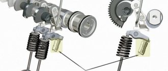
The gas distribution mechanism also requires regular diagnostics. Valve clearances are checked only with the engine idling and the pusher lowered all the way.
Possible malfunctions of the GAZ-53 internal combustion engine
The power unit has breakdowns and malfunctions that are typical for any other engine. To eliminate them, the GAZ-53 engine is completely disassembled and reassembled. The reasons for breakdowns can be different:
- The appearance of knocking of brass liners. This is the most serious malfunction. It is caused by low oil level, wear of all parts, or reduced or completely absent pressure in the system.
- Increased lubricant consumption. Oil can either flow through the seals and connections, or through the piston rings. This could also be caused by a clogged breather.
- Knocking of connecting rod bushings or pistons. Pistons are characterized by burnout of the bottom or failure of the partitions between the rings. The main reason for this is engine overheating.
- Burnout of exhaust valves. They do not burn out by themselves, but you can often encounter wear on the guide bushings. There may be several reasons for this: ingress of engine oil, low quality fuel, or lack of clearance in the valves.
- Burnout of cylinder block gaskets. The reason is overheating of the engine, which can lead to curvature of the surface of the heads.
GAZ-53 engine: technical characteristics. GAZ-53 engine assembly, installation, repair
The modern market is overflowing with a variety of goods. It can be not only of good quality, but also quite bad. And this is not surprising, because companies want to make good profits for less investment. It is worth noting that a modern motor differs not only in quality, but also in cost. In this article we will talk about the gas 53 engine, which is very popular.
The Soviet Union was able to produce a huge number of trucks. All of them are still used today, which is very good. It follows from this that the designers of that time tried to do it efficiently and conscientiously.
The first Gas 53 was designed in 1961. An internal combustion power unit was installed on it. Later, designers used V8-type power units. Thanks to this, it was possible to obtain very high power and torque.
Engine overhaul
With proper care, the GAZ-53 engine rarely needs major repairs, but if this does happen, the following malfunctions may be the cause:
- Increased lubricant consumption, and with the replacement of rings the problem remained relevant.
- Low pressure in the lubrication system and knocking noises in the engine.
- Wear of the entire power unit with exhaustion of its working life.
- Engine jamming due to the crankshaft.
Engine repairs can be carried out independently - the manufacturer issues a complete operating manual, in which all steps for changing parts and possible malfunctions and methods for eliminating them are described in detail.
Despite everything, the engines installed on the GAZ-53 are distinguished by good endurance. Considering the various “modifications” of the internal combustion engine and the oils that are sometimes poured into it, one can only be surprised at its performance. Often such an engine can function quietly for years, even if there are strange knocking noises.
2.5. GAZ-53A and GAZ-66. Engine assembly
To assemble the engine, as well as to disassemble it, the engine cylinder block assembled with the clutch housing is fixed on a stand (see Fig. 11 of the section “2.3.1. GAZ-53A and GAZ-66. Engine disassembly”). Before assembly, all engine parts are selected according to size (Table 4, see section “2.5.1. GAZ-53A and GAZ-66. Dimensions of main parts, clearances and tightness in engine connections”). rinse thoroughly, blow with compressed air and wipe with clean cloths. All threaded connections (studs, plugs, fittings, etc.), if they were removed during disassembly or were replaced with new ones, must be installed on red lead or white lead diluted with natural drying oil. Permanent connections (block plugs and cylinder heads) are installed on nitro varnish. The following are not allowed to be installed on the engine being repaired:
- used cotter pins and cotter wire;
- spring washers that have lost their elasticity;
- bolts and studs with extended threads;
- nuts and bolts with worn edges;
- parts that have more than two nicks or dents on the threads or broken threads;
- damaged gaskets.
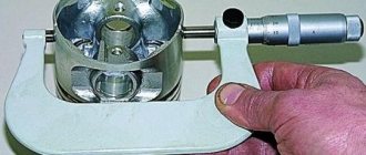
Reassemble the engine in the reverse order of disassembly. Below are some recommendations and additional requirements for engine assembly. When replacing cylinder liners, before installation, the liner is selected according to the socket in the cylinder block. The liners are selected using an accurate metal ruler and a set of feeler gauges as follows: the liner, installed in its place in the cylinder block without sealing gaskets, should be flush against the mating surface of the cylinder block. The ruler is placed on the mating surface, and the probe is inserted into the gap between the ruler and the end of the liner (Fig. 23). The thickness of the gasket is chosen in such a way that after installing the liner with the gasket, its elevation above the surface of the cylinder block is ensured within the range of 0.02 - 0.09 mm.
Rice. 23. Determining the position of the liner in the cylinder block
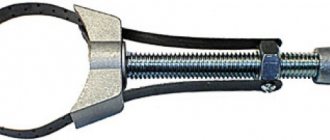
Sealing gaskets are produced in various thicknesses: 0.3; 0.2; 0.15 and 0.1 mm. Depending on the gap, one or another gasket is put on the cylinder liner; sometimes the required value is obtained by a set of gaskets of various thicknesses. After installation in the cylinder block, the liners are secured with bushings-clamps (see Fig. 13 section “2.3.1. GAZ-53A and GAZ-66. Engine disassembly”). An asbestos cord impregnated with an oil-graphite mixture is used as a rear oil seal on engines. A cord 140 mm long is placed in the sockets of the cylinder block and oil seal holder. Using the device, the cord is pressed into its sockets with light blows of a hammer, as shown in Fig. 24. Without removing the device, trim the ends of the cord flush with the plane of the gland holder connector. The cut must be smooth; fraying of the ends and uneven cuts are not allowed.
Rice. 24. Placement of the crankshaft rear oil seal in the oil seal holder
When assembling the crankshaft with flywheel and clutch, observe the following requirements. The flywheel fastening nuts are tightened, providing a torque of 7.6 - 8.3 kgm. When assembling the clutch, the driven disk is installed with a damper to the pressure disk and centered on the crankshaft bearing (the drive shaft of the gearbox can be used as a mandrel). The marks stamped on the pressure disk and flywheel housing near one of the holes for the housing mounting bolts must be aligned. The crankshaft, flywheel and clutch assembly must be dynamically balanced. The permissible imbalance is 70 Gcm. When balancing, remove excess mass from the heavy side by drilling out the flywheel metal at a distance of 6 mm from the ring gear with a drill with a diameter of 8 mm to a depth of no more than 10 mm. If the imbalance of the assembled shaft exceeds 180 Gcm, the shaft is disassembled and each part is balanced separately. The flywheel imbalance should not exceed 35 Gcm; imbalance of the main body assembly with casing - 36 Gcm; Driven disk imbalance—18 Gcm. The main bearing caps are installed so that the locking lugs of the liners are on one side, and the numbers or marks stamped on the caps correspond to the bed numbers. When installing the front cover, it is necessary to ensure that the fixing tendril of the rear thrust bearing washer fits into the groove of the cover and that no steps are formed between the end of the cover and the end of the cylinder block.
Tighten the nuts securing the main bearing caps (torque 11-12 kgm). After tightening and cottering the main bearing cap nuts, the crankshaft should rotate easily with little effort.
Fig.25. Pressing on the crankshaft gear
After pressing on the crankshaft gear (Fig. 25), using a puller and a thrust bushing, check the axial clearance of the crankshaft, to do this, press the crankshaft to the rear end of the engine and use a feeler gauge to determine the gap between the end of the rear thrust bearing washer and the end of the front journal of the crankshaft (Fig. 26). The gap should be in the range of 0.075 - 0.175 mm.
Rice. 26. Checking axial clearance
When assembling parts of the connecting rod and piston group, the following requirements must be observed.
- The piston pins are selected to the connecting rods so that, at room temperature (+18°C), the lightly lubricated pin moves smoothly in the connecting rod bore under light pressure from the thumb.
- Before assembly, the pistons are heated in hot water to +70°C.
Pressing a pin into a cold piston is not allowed, as this can lead to damage to the surfaces of the holes in the piston bosses, as well as to deformation of the piston itself.
Rice. 27. Connecting the connecting rod to the piston:
a - for installation in cylinders 1, 2, 3 and 4; b - cylinders 5,6, 7 and 8;
1-inscription on the piston; 2-number on the connecting rod; 3-mark on the connecting rod cover
Connecting rods and pistons are oriented as follows during assembly:
- for the pistons of the first, second, third and fourth cylinders, the inscription on the piston and the number stamped on the connecting rod rod should be directed in opposite directions, and for the pistons of the fifth, sixth, seventh and eighth cylinders - in the same direction (Fig. 27).
- The piston pin retaining rings are installed in the grooves of the piston bosses so that the bend of the piston pin is directed outward.
- Piston rings are selected according to the liners in which they will work. The gap measured at the joint of the ring placed in the liner should be in the range of 0.3 - 0.5 mm for compression and oil scraper rings. A chrome-plated piston groove is installed in the upper piston groove, and a tin-plated compression ring is installed in the second groove with a groove on the inside towards the bottom. Before installation into the cylinder liners, the joints of the piston rings should be placed at an angle of 120° to each other, and protective brass caps should be placed on the connecting rod bolts to avoid accidental damage to the surface of the connecting rod journals. When installing pistons into cylinder liners, make sure that the inscription on the piston is directed towards the front end of the cylinder block. Tighten the connecting rod bolt nuts (torque 6.8 - 7.5 kgm) and lock.
After pressing the gear onto the camshaft (Fig. 28), use a feeler gauge to check the axial clearance between the thrust flange and the end of the camshaft gear. The gap should be within 0.08 - 0.2 mm.
Rice. 28. Pressing the gear onto the camshaft
When the timing gears are engaged, the crankshaft gear tooth with the mark must fit into the cavity of the camshaft gear teeth marked with a mark. Replace gears as a set, since they are selected at the factory based on lateral clearance and noise during operation. The lateral clearance in engagement should be in the range of 0.03-0.08 mm. When installing on the cylinder block, center the timing gear cover on the front end of the crankshaft using a tapered mandrel to prevent the crankshaft front oil seal from running on one side. Place a tapered mandrel on the front end of the crankshaft and press the timing gear cover against the cylinder block using a ratchet, then tighten the cover securing nuts. The sealing gasket of the oil pickup tube should be placed in the socket in the cylinder block, and not put on the tube. Before installation on the engine, the oil pump is filled with oil. When assembling the cylinder heads, the new valve stems are coated with a mixture consisting of seven parts of a colloidal graphite preparation and three parts of aviation oil. The rocker arm axles are assembled in such a way that the holes for the mounting studs in the axle and struts are shifted in the opposite direction from the rocker arm adjusting bolts. The inlet pipe fastening nuts are tightened with moderate force, since the rubber gaskets cannot limit the tightening to the stop and when the nuts are tightened, the rubber gaskets may be crushed. The breaker-distributor drive must be installed in this sequence.
- Set the piston of cylinder 1 to the top dead center (TDC) position on the compression stroke.
- Insert the breaker-distributor drive into the hole in the cylinder block so that the slot in the drive shaft is directed along the engine axis and shifted to the left, counting as the vehicle moves.
- Secure the drive housing with a holder and a nut so that the bracket with a threaded hole for attaching the breaker-distributor is directed back and turned at an angle of 23° to the left from the longitudinal axis of the engine, as shown in Fig. 29.
- Before installing the distributor-breaker on the engine, you should check the gap in the breaker contacts and, if necessary, adjust it. The gap in the contacts should be within 0.3 - 0.4 mm.
- Using the octane corrector nuts, turn the body of the breaker-distributor so that the arrow points to the zero scale mark.
- Turn the distributor rotor so that it faces the terminal of the first cylinder. Terminal of the first cylinder on the ignition distributor cover o. Put on the distributor cap with wires and connect the latter to the spark plugs in the order of operation of the engine cylinders (1 - 5 - 4 - 2 - 6 - 3 - 7 - 8). The firing order is cast on the engine intake manifold.
Rice. 29. Installation of the breaker-distributor drive
Repair of the ZMZ-53-11 engine. Engine assembly. Part 1.
Repair of the ZMZ-53-11 engine. Engine assembly.
Part 1
To assemble the ZMZ-53-11 engine , as well as to disassemble it, the cylinder block must be mounted on a rotating stand, which provides free access to all engine parts and components.
Before assembling the engine, all parts of the ZMZ-53-11 engine must be thoroughly washed, blown with compressed air and wiped with clean cloths. All threaded connections (studs, plugs, fittings, etc.), if they were removed during disassembly or replaced with new ones, must be installed with red lead or whitewash diluted with drying oil. Permanent connections (plugs) must be installed with nitro varnish.
The following are not allowed for installation on the engine:
- used cotter pins and locking plates;
- spring washers that have lost their elasticity;
- bolts and studs with extended threads;
- nuts and bolts with worn edges;
- parts that have more than two nicks or broken threads on the threads;
- damaged gaskets.
Bolts, studs and nuts must fully comply with these specifications. Where required by design, nuts and bolts must be tightened in an appropriate manner (cotter pins, locking plates, spring washers, special washers and locknuts).
When assembling the ZMZ-53-11 engine, the following order of operations must be observed:
1. Install the cylinder liners into the cylinder block. The selection of sleeves is carried out using an accurate metal ruler and a feeler gauge as follows: the sleeve, installed in its place in the block, without a sealing gasket, should be flush with respect to the mating plane of the head. The ruler is installed on the mating plane, and the probe is inserted into the gap between the ruler and the end of the sleeve (Fig. 55). The thickness of the gasket is selected so that after installation the sleeve protrudes above the surface of the block within 0.02-0.10 mm.
Sealing gaskets are manufactured in various thicknesses: 0.15, 0.18, 0.20 and 0.30 mm. Depending on the size of the gap, one or another gasket is put on the cylinder liner. Sometimes the required size is provided by a set of two or three spacers.
After installation into the block, the sleeves must be secured against falling out with special bushings-clamps (Fig. 36).
2. Place the rear crankshaft oil seal in the sockets of the block and oil seal holder. An asbestos cord impregnated with an oil-graphite mixture is used as a rear oil seal on the engine. A cord 120 mm long is placed in the sockets of the block and the oil seal holder. Using a special device, the cord is pressed
is hammered into its sockets by lightly tapping with a hammer, as shown in Fig. 56. Without removing the device, trim the ends of the cord, protruding the ends above the connector plane by 0.5 - 1.0 mm. The cut must be smooth; fraying of the ends and uneven cuts are not allowed.
3. Assemble the crankshaft:
- a) press the gearbox input shaft bearing into the crankshaft socket;
- b) install the flywheel on the shaft and secure it with four special bolts and nuts. Place two locking plates under the nuts and tighten the nuts with a wrench to a torque of 7.6 - 8.3 daNm (7.6 - 8.3 kgfm). Bend the locking plates one at a time onto the nuts and cotter the flywheel mounting nuts;
- c) screw the pressure plate with housing assembly to the flywheel, having previously centered the clutch driven disc using a mandrel (the input shaft of the gearbox can be used as a mandrel) along the bearing at the rear end of the crankshaft. The 0 marks stamped on the pressure plate housing and flywheel near one of the holes for the housing mounting bolts must be aligned (Fig. 57). Tighten the housing mounting bolts with a torque of 2 - 2.5 daNm (2 - 2.5 kgf m).
The driven disk is installed with a damper to the pressure disk. The crankshaft/flywheel/clutch assembly is balanced at the factory, so it is recommended that the crankshaft be dynamically rebalanced after replacing one of these parts. The imbalance should not exceed 30 g cm. Before balancing the crankshaft, place a weight weighing 2372 g on the connecting rod journals. When balancing, it is recommended to remove excess weight from the heavy side by drilling the flywheel metal at a distance of 6 mm from the ring gear with a drill with a diameter of 8 mm, to a depth of no more than 10 mm, the distance between the centers of the holes is not less than 15 mm.
If the imbalance of the assembled crankshaft exceeds 180 g cm, then it is necessary to disassemble the shaft and balance each part separately.
The crankshaft is dynamically balanced. The permissible imbalance is 15 g cm. The remaining parts are balanced statically. The permissible imbalance of the flywheel is 35 g cm, the clutch driven disc is 18 g cm, the clutch pressure plate with housing assembly is 36 g cm.
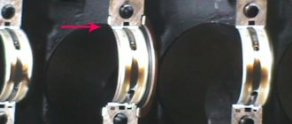
4. Place the main bearing shells in the block housings and the main bearing caps.
5. Place the rear thrust bearing washer on the front journal of the crankshaft with the aluminum side facing the crankshaft.
6. Lubricate the main bearing shells and crankshaft journals with clean engine oil and place the shaft in the cylinder block.
7. Place the main bearing caps on the studs so that the locking lugs on the upper and lower shells of each bearing are on one side, and the numbers stamped on the caps correspond to the numbers of the block shell shells. When installing the front cover, it is necessary to ensure that the fixing tendril of the rear thrust bearing washer fits into the groove of the cover and that a step does not form between the end of the cover and the end of the block.
8. Place the lids in place by lightly tapping them with a rubber mallet. Install the locking plates. Screw on the nuts securing the covers and tighten them evenly, making sure that there are no distortions.
The final tightening of these nuts is carried out with a torque wrench with a torque of 10 - 11 daNm (10 - 11 kgfm). At the edge of the nuts, bend the antennae of the locking plates. After tightening the nuts, the crankshaft should rotate easily with little effort.
9. Reinstall the oil seal holder. Before installation, insert rubber side sealing gaskets into the grooves of the oil seal holder. Place flat and spring washers on the studs and screw on the special oil seal nuts.
10. Place the front thrust bearing washer with the aluminum side facing the toe of the crankshaft so that with its grooves it is installed on the pins pressed into the block and the front main bearing cap.
Continue reading the article here: part 2, part 3
Engine repair ZMZ 53
With moderate oil consumption, many drivers continue to use the Lawn, and repair the engine only when the consumption (waste) exceeds two liters per thousand kilometers. Crankshafts knocking on engines is not so rare, but the drivers themselves are often to blame for this, the Lawn is a workhorse, and car owners often load the car to the limit of how much it can carry.
To “recapitalize” the engine, it must be removed, disassembled and defective. If the knocking crankshaft is not greatly deformed, it can still be ground, but a lot depends on the repair size that the shaft has. The shaft has never been ground; it has a standard size (main journals - 70 mm, connecting rod journals - 60 mm). In total, the GAZ 53 crankshaft has six repair sizes, they go every 0.25 mm.
A common “disease” of Gas engines is wear of the camshaft bushings (supports); at the same time, the support journals also wear out at the r/shaft itself. But if it’s easy to change the shaft, then with the bushings it’s already more difficult; repairing the ZMZ 53 engine is not easy:
- old bushings must be pressed out and new bushings must be pressed in;
- After pressing the bushings under the camshaft supports, they must be processed with a special reamer.
This work requires special tools, accuracy and patience - if the bushings “sag”, you will have to buy new parts and redo everything all over again. If you don’t bother with adjustments and just change the camshaft, the pressure in the oil system will be weak and the internal combustion engine may knock quite quickly.
Recently, in modifications of 53 engines, the cylinder blocks are sleeveless, that is, the camshaft rotates in aluminum supports. If over time the supports in the block wear out, you have to either change the block or re-fit it at the factory - it will no longer be possible to “re-fit” the BC yourself.
During overhaul, the piston group is usually changed entirely, although often (especially earlier, in Soviet times) cylinder liners were bored out and repair pistons were installed in them. On the ZMZ-53 engine there are a total of three repair sizes:
- +0.5 mm;
- +1.0 mm;
- +1.5 mm.
If we take into account that the standard piston has a diameter of 92 mm, then the piston of the last repair will have a size larger by 1.5 mm, that is, its diameter will be equal to 93.5 mm.
When overhauling the ZMZ-53, you should also pay attention to the condition of the upper connecting rod heads - copper bushings are installed in them, which wear out over time. If there is play between the piston pin and the bushing, the engine will knock, and this knock is very unpleasant. Subsequently, the bushing begins to crumble, and then the knocking becomes very strong - it is impossible to drive such a motor.