What happens when recirculation is turned on
In order to understand correctly, it is necessary to understand two concepts: circulation and recirculation.
The first means that the air inside the car is constantly renewed, that is, it flows in and out.
In the second case, there is no air renewal. When the recirculation function is turned on, a special flap blocks the access of fresh air flow inside the car. As a result of this, a circular movement of the air flow in the cabin occurs inside the car.
Drivers do not use this function very often, but it has several significant advantages.
ENGINE AIR SUPPLY AND EXHAUST SYSTEM
ENGINE AIR SUPPLY AND EXHAUST SYSTEM
Rice. 46. Diagram of the engine air supply and exhaust gas exhaust system: 1 - gas breather pipe; 2 — breather; 3 — oil drain pipe of the breather; 4 — engine intake air duct; 5 — air cleaner; 6 — exhaust manifold; 7 — outlet pipe; 8 — muffler; I - air from the atmosphere; II - purified air; III - crankcase gases; IV-exhaust gases
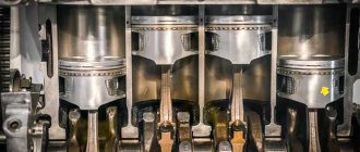
The engine air supply system is designed to take air from the atmosphere, clean it from dust and distribute it among the cylinders. The system diagram is shown in Fig. 46. Atmospheric air is sucked: into the engine cylinders, passing through the air cleaner 5. The purified air is distributed by the intake manifolds across the engine cylinders and participates in combustion as part of the working mixture. Exhaust gases pass through the exhaust manifolds, exhaust pipes of the muffler and are released into the atmosphere through the muffler. Gases that have penetrated into the engine crankcase through the gaps between the cylinder mirror and the piston rings are removed into the atmosphere through the pipe and exhaust pipe due to excess pressure.
In Fig. 47 shows air intake systems used on various models of KamAZ vehicles. Air is taken into the engine through the air intake. Between the air intake pipe and the air ducts attached to the engine, there is a seal - a corrugated rubber pipe, inside of which a pressure disk is inserted, which serves as a support for the spacer spring. The latter ensures the tightness of the connection between the seal and the air intake pipe during the transport position of the cabin. Air cleaner 4 (Fig. 47, a) of KamAZ-5320 and KamAZ-55102 vehicles is attached to the left frame side member. On other vehicles (Fig. 47, b and c), the air cleaner is mounted on bracket 5.
Dry type air cleaner, two-stage. The first centrifugal stage is a monocyclone with collection of separated dust into a hopper, the second stage is a paper filter element. The air purifier (Fig. 49) consists of a housing 8, a filter element 5, a cover 1 attached to the housing with four latches. The tightness of the connection is ensured by gasket 2. In the internal cavity of the lid there is a partition with a slot and a plug, which forms a dust collection cavity (hopper). There is a dust separator 4 at the inlet pipe of the air cleaner. The filter element is secured in the housing with a self-locking nut 6.
The sucked air enters the filter through the inlet pipe. The dust separator creates a rotational movement of the air flow in the annular gap between the housing and the filter element; due to the action of centrifugal forces, dust particles are thrown towards the wall of the housing and collected in the hopper through a gap in the partition.
Then the pre-cleaned air: passes through the filter element, where it is finally cleaned. To clean the hopper from dust, remove the cover, remove the plug from the hole in the partition, remove dust and wipe the hopper.
The cover should be installed so that the arrow on the bottom is directed upward when the filter is positioned horizontally (KAMAZ-55111, KamAZ-5410, KamAZ-54112 vehicles).
Clean air from the air cleaner flows to the engine intake manifolds.
To increase the efficiency of cleaning the air entering the engine and increase the service life of the filter element, a pre-cleaner is installed in the air cleaner (Fig. 50). The pre-cleaner is a shell made of non-woven filter fabric, which is put on the filter element before installing it in the filter housing.
The intake air ducts are fixed on the side surfaces of the cylinder heads on the camber side with bolts through sealing paronite gaskets and connected to the inlet channels of the cylinder heads. The inlet air ducts of the left and right halves of the block are connected to each other by a connecting pipe. The pipe is secured to the flanges of the air ducts with bolts. The connections between the pipe and the intake air ducts are sealed with rubber gaskets.
The air supply system of the KamAZ-7403 engine differs from the KamAZ-740 engine in the installation of an air cleaner, the design of air ducts, intake manifolds and pipes.
Clean air from the air cleaner is supplied through a tee to two centrifugal compressors and, under an excess pressure of 70 kPa (0.7 kgf/cm2) in maximum power mode, is supplied through the intake manifolds to
cylinders.
The connection of the air supply tee to the compressors and the compressors to the intake manifolds is ensured by rubber pipes and hoses, which are tightened with clamps.
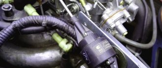
The air cleaner clogged indicator (Fig. 51) is installed on the instrument panel and is connected to the engine intake manifold with a rubber hose. When a maximum vacuum of 6.86 kPa (0.07 kgf/cm2) is reached in the engine intake manifolds, the indicator is activated - the red section of the drum closes the indicator window and remains in this position after the engine is stopped. This indicates a need for maintenance.
air purifier.
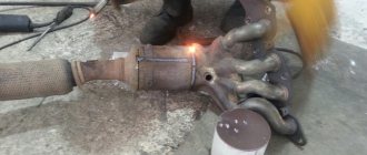
The exhaust system (Fig. 52) is designed to release exhaust gases into the atmosphere. The system consists of two exhaust manifolds 9, two exhaust pipes 7 and 8, a flexible metal hose 5, and a muffler 1.
Each exhaust manifold serves a bank of cylinders and is secured to the cylinder block with three bolts. The manifolds are connected to the cylinder heads by pipes. The detachable design of the manifold-pipe-head connection makes it possible to compensate for thermal deformations that occur during engine operation.
The intake pipes are united by a tee: and connected to the muffler by a flexible metal sleeve, which compensates for assembly errors and temperature deformations of system parts. A damper for the auxiliary engine brake system is installed in each downpipe.
The exhaust noise silencer (Fig. 53) is active-reactive, non-demountable. An active muffler operates on the principle of converting sound energy into thermal energy, which is carried out by installing perforated partitions in the path of gases, in the holes of which the gas flow is crushed and the pulsation is damped. The reactive muffler uses the principle of acoustic sound filtering. This muffler consists of a series of acoustic chambers connected in series.
An exhaust pipe 2 (Fig. 54) is installed on the exhaust pipe of the muffler of the KamAZ-55111 dump truck, designed to heat the platform with exhaust gases in the cold season. When operating a KamAZ-55111 dump truck in the cold season, to heat the platform, remove the plug from the vertical muffler pipe and install it between the tee pipe and the exhaust pipe. In the warm season, install a plug on the vertical pipe of the muffler, removing it from the tee pipe.
The gas turbine charging system consists of two interchangeable turbochargers, compressors, intake and exhaust manifolds and pipes. Turbochargers are installed on the exhaust manifolds, one for each bank of cylinders. Gas joints between the mounting flanges of turbochargers and manifolds are sealed with gaskets made of heat-resistant steel.
The exhaust gas exhaust pipe is attached to the turbochargers using tension flanges, and the tightness of the connections is ensured by an asbestos-steel gasket.
The turbocharger bearings are lubricated by the engine lubrication system.
Turbocompressor TKR7N (Fig. 55) is a unit that combines a centripetal turbine and a centrifugal compressor. The turbine converts the energy of gases into the work of compressing air by a compressor.
The rotating part of the turbocompressor - the rotor - consists of a turbine wheel 16 (see Fig. 55) with a shaft, a compressor wheel 8 and an oil deflector 7, secured to the shaft with a nut 6.
The rotor rotates in bearing 1, which is a floating non-rotating mono-hub, and is held from axial and radial movements by a retainer 12, which, together with adapter 13, is an oil supply channel. In the bearing housing 11, steel covers 10 and 18 and an oil discharge screen 9 are installed, which, together with non-rotating elastic split sealing rings 5, prevents oil leakage from the cavity of the bearing housing.
The turbine and compressor housings are attached to the bearing housing using bolts and strips. To reduce heat transfer from the turbine housing to the bearing housing, a cast iron turbine screen 15 and an asbestos steel gasket 14 are installed between them. Diffuser 4 and screen 2 form a channel through which air, after being compressed in the wheel, is supplied to the internal cavity of the housing.
Rice. 47. Diagram of air intake systems for cars: a - models 5320 and 55102; b - models 53212, 5410 and 54112; c - model 55111; 1 - cap; 2 — air intake pipe; 3 — seal: 4 — air cleaner; 5 — bracket (arrows indicate places subject to tightness control when servicing the system)
Rice. 48. Installation of air purifiers: a) with cabins without a berth; b) with cabins with a berth; 1-bracket; 2-air purifier; 3-spring stop; 4-seal; 5-spacer spring; 6-pressure disc; 7-adapter; 8-pipe; 9-air intake hood; 10-cabin; 11-connection intake manifold pipe; 12-device “Winter-summer”; 13-clutch housing
Rice. 52. Exhaust system: 1-connecting pipes; 2-tension flanges; 3-turbocompressors; 4, 8-pipe exhaust gases; 5-muffler; 6-muffler mounting brackets; 7-frame spar
Rice. 55. Turbocharger: 1 - bearing; 2 — screen; 3-compressor housing; 4 — diffuser; 5, 19 — sealing ring; 6 - nut; 7 — oil deflector; 8 - compressor wheel; 9 — oil discharge screen; 10, 18 — covers; 11 — bearing housing; 12 — clamp; 13 - adapter; 14 — asbestos-steel gasket; 15 — turbine screen; 16 — turbine wheel; 17 — turbine housing
Acceleration of cooling and heating of air in the car
Thanks to recirculation in winter, you can warm up the car interior much faster, because the cold air flow constantly coming from the street will increase the warm-up time. And if you block the air flow, then the air in the cabin, moving in a circle, will warm up much faster.
This also works in the summer, when the car interior needs to be cooled. This procedure will take much less time if you turn on recirculation.
As a result, energy costs for operating the air conditioner are significantly reduced.
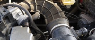
Reasons for airing the cooling system
- Worn cylinder valve body gasket. If this happens to your engine, then most likely coolant will penetrate the cylinders. This can be seen in the white exhaust, and if you look into the expansion tank, you can see seething there. This gurgling sound occurs because exhaust gases enter the cooling system and exit through the expansion tank. After such problems, you should replace the cylinder head gasket and be sure to replace the antifreeze, because after contact with exhaust gases it becomes unusable.
- Antifreeze leak. If there is an antifreeze leak, then it is immediately clear why airing occurs. The fact is that only air is supplied to the CO to replace antifreeze. Leaks can occur in different places, for example, radiators, cylinder head gasket, pump, pipes, and so on. It is not difficult to detect a leak; you just need to carefully inspect the engine and chassis of the car. After detecting a leak and eliminating the malfunction, an inspection of the entire system should be done, as new problems could arise due to air ingress.
In order for antifreeze to function well in the system in winter, you can use the table below.
Coolant temperature °C
Coolant concentration
Specific gravity of antifreeze at temperature, kg/l
- Pump failure. Air may enter the system due to a breakdown of the pump, or more specifically, certain parts of it: fiber or seal. When small defects appear in these elements, during operation the pump begins to let air into the system, and this in the future leads to airing. That is why if you begin to notice improper operation of the CO, you should check how the pump functions.
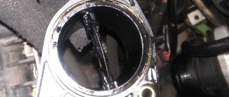
How to remove air from the cooling system?
In fact, there is no universal recipe or guaranteed methods for removing air from the cooling system. If only for the simple reason that the designs of the systems are different. Some are simpler, others have a lot of additional elements and “assisting” mechanisms. It all depends on the class and purpose of the car.
The Internet is full of all sorts of recipes on how to remove an air lock “on your own in a garage,” but, I repeat, each engine and each system has its own specifics, and no one can do it better than a specialist. And the most common “home-grown” techniques are considered to be two.
Method one
Remove attachments and all protective elements from the engine in the area of the expansion tank. Disconnect one of the pipes, which is responsible, for example, for heating the throttle valve (if you understand and know what we are talking about). Blow inside the expansion tank, and excess pressure in the system will force excess air through the removed pipe.
As soon as water (antifreeze) comes out of the removed pipe, immediately put it back in place.
Method two
How to remove an air lock from a “simple” motor? Place the vehicle on an elevated position so that the front end and therefore the radiator cap are higher than the rest of the cooling system. Run the engine for 10-15 minutes to allow the thermostat to operate and open the large cooling circuit. Remove (carefully!) the cap from the expansion tank or radiator, whichever is higher at the moment.
This method, I repeat, is suitable for cars of older designs without “all sorts of electronic and other problems.” However, even on such cars, the mechanic sometimes leans deep into the engine compartment and, like a pear, pumps and presses alternately the upper and/or lower radiator hose in order to expel and remove air from the cooling system.