Distinctive features of gas turbine engines
Today, this type of motor is most widely used in aviation. Unfortunately, due to the nature of the device, they cannot be used for ordinary passenger cars.
Compared to other internal combustion units, the gas turbine engine has the highest specific power, which is its main advantage . In addition, such an engine is capable of operating not only on gasoline, but also on many other types of liquid fuel. As a rule, it runs on kerosene or diesel fuel.
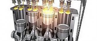
Gas turbine and piston engines, which are installed on passenger cars, change the chemical energy of the fuel into thermal and then mechanical energy by burning fuel.
But the process itself is slightly different for these units. In both engines, the intake is first carried out (that is, the air flow enters the engine), then the fuel is compressed and injected, after which the fuel assembly ignites, as a result of which it expands greatly and is ultimately released into the atmosphere.
The difference is that in gas turbine devices all this takes place at the same time, but in different parts of the unit. In a piston engine, everything is carried out at one point, but in order.
Passing through a turbine engine, the air is greatly compressed in volume and, as a result, increases the pressure by almost forty times.
The only movement in the turbine is rotational, when, as in other internal combustion units, in addition to the rotation of the crankshaft, the piston also moves.
The efficiency and power of a gas turbine engine are higher than that of a piston engine, despite the fact that the weight and dimensions are smaller.
For economical fuel consumption, the gas turbine is equipped with a heat exchanger - a ceramic disk, which operates from the engine at a low rotation speed.
Advantages and disadvantages of gas turbine engines
It would seem that if a gas turbine engine is so powerful, then it would be logical to see it under the hood of some racing car, but even Formula 1 cars still run on the same piston engine.
Disadvantages of gas turbine engines
High inertia. In order to bring a gas turbine engine to maximum power, it takes incomparably more time than a classic gasoline or even diesel engine. This drawback will clearly manifest itself when starting off at a traffic light.
Low efficiency. If you know well the theory of the structure of a classic internal combustion engine, then you understand that before combustion, the air in the chamber is compressed 10-13 times. For a piston circuit, performing such a trick is not very difficult, but turbine blades can provide a similar compression ratio only after reaching the maximum rotor speed. Consequently, high efficiency is achievable only at maximum power; in other cases, the gas turbine engine will simply consume liters of fuel.
High noise level. Based on the perception of the human ear, high frequencies seem much louder than low frequencies. But the gas turbine engine generates a huge variety of high-frequency sound vibrations, which are very irritating to the ear. This is the reason why helicopter pilots wear headphones to talk to other crew members.
High price. Since the rotor of a gas turbine engine simply rotates at breakneck speed, the slightest error in balancing will inevitably lead to the collapse of the entire structure. Moreover, high temperatures require the use of special structural materials, which cost several times more than conventional steel.
Maintenance problems. If a classic engine can still be somehow repaired without having complex equipment, then such a trick will not work with a gas turbine engine, which means that expensive services of specialists and their equipment will be required.
The complexity of the transmission device. The rotor shaft of a gas turbine engine rotates at a speed of several thousand revolutions per minute, while the wheels of a car rotate at a couple of hundred revolutions per minute. Therefore, to convert the torque, a gearbox with a very high gear ratio is required. This results in design complexity and friction losses.
Advantages of gas turbine engines
High efficiency at maximum power. In order to fully realize this advantage, the car must be built using a hybrid scheme.
Multi-fuel. The engine can run on almost any liquid combustible fuel.
Easy to start in extreme sub-zero temperatures. To start the engine in question in severe cold, you need an order of magnitude less effort. From the material reviewed, we can conclude that the future use of gas turbine engines in vehicles is promising only in the hybrid scheme. But, however, the cardinal advantage of the gas turbine engine, even in this case, is also not obvious, but the difference in cost is quite clear.
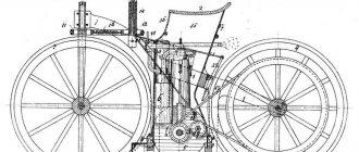
Design and principle of operation of the unit
The design of the engine is not very complex; it is represented by a combustion chamber, where nozzles and spark plugs are equipped, which are necessary to supply fuel and produce a spark charge. The compressor is equipped on a shaft together with a wheel with special blades.
In addition, the motor consists of such components as a gearbox, an intake duct, a heat exchanger, a needle, a diffuser and an exhaust pipe.
As the compressor shaft rotates, the air flow entering through the intake duct is captured by its blades. After increasing the compressor speed to five hundred m per second, it is pumped into the diffuser. The speed of the air at the outlet of the diffuser decreases, but the pressure increases. Then the air flow ends up in a heat exchanger, where it is heated by exhaust gases, and after that the air is supplied to the combustion chamber.
Along with it, fuel gets there, which is sprayed through the nozzles. After the fuel is mixed with air, a fuel-air mixture is created, which ignites due to the spark received from the spark plug. At the same time, the pressure in the chamber begins to increase, and the turbine wheel is driven by gases falling on the wheel blades.
As a result, the torque of the wheel is transferred to the car’s transmission, and the exhaust gases are released into the atmosphere.
All about gas transport
3. Basic parameters characterizing the stage and the axial compressor as a whole
These parameters are:
a) degree of stage reactivity ρ; b) efficiency of the stage and compressor ηst and ηk; c) the degree of increase in air pressure in the stage and compressor πst, and πk; d) peripheral speed and U swirl of air in the RK ΔWu or ΔCu. e) stage performance Gв. f) the power required to rotate the compressor Nk. A) . Stage reactivity degree ρ. The degree of stage reactivity shows the distribution of compression work between the stage elements OK, RK and SA; It is equal to the ratio of the adiabatic work of air compression in the RK Lad rk to the stage Ladst - i.e. ρ =
The value of ρ can vary from 0 to 1. If ρ = 1, then L adrc = Laadst - This means that air compression is carried out only in the RK, and in the SA only rotation (spin-up) of the flow is carried out. In this case, the SA performs the functions of only a guiding apparatus. When ρ=0 ; Ladrk = 0. All air compression is carried out in the SA. In the Republic of Kazakhstan, only an increase in the kinetic energy of the flow is produced. The most optimal value is ρ = 0.5 - 0.8.
b). Stage and compressor efficiency (ηst and ηk)
The efficiency of a stage is the ratio of the adiabatic work of compression of 1 kg of air Ladst to the effective work Lest i.e. to the work supplied to the stage impeller shaft.
ηst =
The stage efficiency takes into account all losses along the way of converting mechanical work on the compressor shaft into air pressure energy: losses due to friction, vortex formation and air flow in the gaps. For modern OKs ηst = 0.88–0.91. The efficiency of a centrifugal compressor stage (centrifugal compressors are usually single-stage) is much lower than that of an axial compressor and is equal to ηcc = 0.73–0.78. This is explained by the fact that the OK does not have such sharp flow turns as in the CC, and the aerodynamics of the OK blades are also much better than the CC. In general, the efficiency of OK is 3–5% less than that of its stage and is equal to ηк = 0.82–0.85.
V). The degree of air pressure increase in the stage and compressor
The degree of air pressure increase is the most important parameter characterizing the compressor. The degree of increase in air pressure in a stage is the ratio of the pressure at the outlet of the stage (exit from the SA) P2 to the pressure at the inlet to the stage (input to the RK) P1 (Fig. 14).
Rice. 14
πst = For completed OK
πst = 1.2-1.3.
The degree of increase in air pressure in a compressor is the ratio of the pressure at the outlet of the last stage of the compressor Pk to the pressure at the inlet of the first stage P1. πк =
It is easy to show that the degree of increase in air pressure in the compressor is equal to the product of the degrees of increase in air pressure in stages πк = πст1 · πст2 · πст3 · · · πст к From this it follows that the pressure of the compressor depends on the number of stages. The completed OK ones have a number of steps from 5 to 15, and πк = 5–16. In CC, the pressure is limited to πк = 4–5. Using the dependence Ladst = ηst · Lest, we derive a formula for analyzing the dependence of πst on various factors
Considering that for air a , we get
From the resulting equation it is clear that the degree of increase in air pressure in the compressor stage πst (stage pressure) is greater, the greater the peripheral speed of the impeller or the rotor speed U =, the air swirl in the compressor (ΔСu) and the efficiency of the stage ηst and the lower the air temperature at the entrance to the step.
G). Peripheral speed u and air swirl in the impeller Δсu. These parameters mainly determine the pressure of the stage. The pressure can be increased by increasing the peripheral speed U. However, the increase in the peripheral speed U, on the one hand, is limited by the strength conditions of the rotor, on the other hand, by the maximum value of the relative speed W1max, at which the number M1≤0.8. In this regard, for completed OKs, the peripheral speed on the outer diameter is equal to U = 300-370 m/s. On some compressors, in order to increase the peripheral speed U without increasing the relative speed W1 max, a preliminary swirl of air is created before entering the AC. Preliminary air swirl is created by a guide vane (VA) installed at the entrance to the stage. The amount of air swirl in the rotor ΔWu = ΔCu is estimated using the swirl coefficient
Substituting the value of the coefficient μ, we get
The greater the air swirl in the AC or the swirl coefficient, the greater the effective work of the stage Lest, and therefore the greater the pressure of the stage πst. However, an excessive increase in the coefficient μ leads to an increase in hydraulic resistance, as flow turns become sharper. This reduces the efficiency of the stage and compressor. Therefore, on completed OKs μ = 0.4 – 0.5.
1.5. UNSTABLE OPERATION OF AN AXIAL COMPRESSOR AND COMBATING IT 1. The essence of surge Stages of an axial compressor
Unstable operation of an axial compressor stage can occur, just like in a centrifugal compressor, only when the air flow rate decreases from the calculated value. A decrease in air flow rate from the calculated value (reduction in the axial component of the absolute speed C1a) leads to an expansion of the vortex zone formed in the region of low pressure on the backs of the blades , spreading along the entire length of the channel (see Fig. 15). The same thing happens when flow around the blades of the straightening apparatus. The signs of surge are the same as for a centrifugal compressor/
Rice. 15
2. Surge of a multi-stage axial compressor
To find out the conditions for the occurrence of surge at stages, it is necessary to consider how the axial velocities change along the compressor in off-design modes, remembering that reducing them from the design ones can lead to breakdowns and surge. The areas of flow sections and steps are selected for the design mode. A change in air flow or speed from the calculated values leads to a redistribution of the axial speeds among the compressor stages.
From the condition of equality of flow rates at the entrance to the first stage I and the exit from compressor II it follows (Fig. 16)
Rice. 16
GВ = С1а· γI·f1= C2а· γII and ; but from the polytropic equation or
Let point A on the compressor operating characteristic (Fig. 17) correspond to the design mode. Let's analyze how the speed ratio СIa/СIIa changes when the engine operating modes change.
Rice. 17
A). Engine throttling (reducing npr on the compressor characteristic (Fig. 17a) operating point A moves towards the pressure curve npr3 < npr2) leads to a decrease in the reduced weight air flow rate Gpr. and πk. A decrease in πk leads to a decrease in the CIa/CIIa ratio. The decrease in the CIa / CIIa ratio occurs mainly due to a decrease in CIa, the value of which decreases more intensively than CIIa. This is explained as follows. At the first stage of the compressor, the value of πk is small and therefore its decrease during throttling has almost no effect on the value of the specific gravity of air γI. The decrease in the weight air flow Gв = VвI γI occurs mainly due to a decrease in the volumetric air flow VвI = СIа • f1, - i.e., a decrease in the speed СIа, since the cross-sectional area f1 is a constant value. The operating point on the characteristic of the first stages of the compressor is approaching the surge limit. A decrease in the speed CIa leads to an increase in the angle of attack on the impeller blades of the first stages; the stages, as they say, “become heavier” (Fig. 17b). At the last stages, where the value of πk is large, its decrease leads to a significant decrease in γII. Therefore, a decrease in Gв occurs due to a decrease in γII with an increase in the volume flow VвII = СIIa · γII (or a decrease to a much lesser extent than VвI), i.e., an increase in СIIa, since f II = Const. The angles of attack on the impeller blades of the last stages decrease, the stages become “lighter” (Fig. 17b). The operating point on the characteristic of the last stages of the compressor moves away from the surge boundary. Conclusion: when throttling the engine, surging may occur primarily in the first stages of the compressor.
b). Engine acceleration (an increase in npr - in the compressor characteristic Fig. 17a, operating point A moves towards the pressure curve npr1 > npr2) leads to an increase in the speed ratio CIa / CIIa due to an increase in CIa and a slight decrease in CIa. The operating point of the characteristics of the first stages moves away from the surge boundary, and that of the last stages approaches it. Conclusion - when accelerating the engine, the likelihood of surge occurring is greater in the last stages. In practice, surging of the last stages is almost never observed.
3. Constructive measures to combat surge
A). Bypassing air when throttling the engine from adjacent compressor stages into the atmosphere through anti-surge valves (Fig. 18), in order to maintain constant (close to design) air flow through the first stages, while the total air flow through the compressor decreases. The opening of the anti-surge valves occurs automatically when the engine is throttled to a certain given speed. When throttling the engine, the operating point on the compressor characteristic moves from A to B (Fig. 18), and the operating point of the characteristic of the first stages approaches the surge limit
Rice. 18
Rice. 19
(point “B”), and the last steps move away from it (point “B”). When the CPV opens, point “B” moves away from the surge boundary, and point “B” moves into the region of large πk and ηk. Conclusion: bypassing air from the middle stages to the atmosphere eliminates the possibility of surge at reduced engine operating conditions. The disadvantage of this method is the loss of power spent on compressing the air released into the atmosphere. b). Application of rotary vanes of the guide vane. The adjustment angle of the guide vane blades is changed automatically depending on the engine operating mode, ensuring shock-free air entry into the compressor impeller. This increases the efficiency of the compressor and shifts the area of unstable operation of the compressor to non-operational operating modes of the engine. When the degree of increase in air pressure in the compressor is large (πк > a combination of the indicated methods of combating surge is used. c). An effective method of combating surge is the use of a two-stage (two-shaft) compressor.
4. Double-stage (double-shaft) compressor
The high-pressure, multi-stage axial compressor is divided into two parts: a low-pressure cascade and a high-pressure cascade. The impellers of the low and high pressure cascades are each rotated by its own turbine. The impeller and turbine of the low-pressure cascade are a low-pressure rotor (LPR), and the impeller and turbine of a high-pressure cascade are a high-pressure rotor (HPR) (Fig. 20).
Rice. 20
Between the RND and RVD there is only a gas-dynamic connection and, in the general case, the revolutions nрнд ≠nрвд. Usually the speed is nрд > nрнd by 30-50%.
By using a twin-shaft compressor, one high-pressure compressor is actually replaced by two low-pressure compressors located in series, which have more favorable characteristics. The pressure of each cascade πkrnd and πkrvd does not exceed 3-4, with the total pressure of the compressor πk = 9-16. In a high-pressure axial compressor, as has been shown, a decrease in πк (engine throttling) leads to “heavier” of the first and “lightening” of the last stages, i.e., the required power for rotation of the first stages Nkrnd increases, and the last stages Nkrvd decreases. When throttling the engine, the power developed by the RSD turbine Ntrnd decreases, while the RVD turbine Ntrvd remains unchanged in a certain range of modes. An increase in the required power Ncrnd with a decreasing available turbine power Ntrnd leads to a decrease in the low-pressure rotor speed nrnd, and a decrease in Ncrp with a constant turbine power Ntrd leads to an increase in the high-pressure rotor speed nprd. Such an automatic change in the speed of the low and high pressure rotors when changing operating modes of the engine (in this case, throttling) helps maintain a shock-free air entry into the compressor impeller, ensuring its stable operation with a high efficiency value (Fig. 21). Due to the fact that as a result of throttling the engine nрдп > nрнд, the first compressor stage will operate at a relatively higher air flow rate due to air being sucked through it by the rotor of the second cascade. Conclusion: the use of a two-stage compressor eliminates the possibility of surge modes in a wide range of engine operating conditions.
Rice. 21
Theoretically, it is advisable that when the operating modes of the engine change, the impeller of each stage rotates at its own peripheral speed, i.e., so that the number of cascades is equal to the number of stages. This is difficult to do structurally. Therefore, two and much less often three-stage compressors have been used in practice.
2. ORGANIZATION OF THE COMBUSTION PROCESS IN THE COMBUSTION CHAMBERS OF TRD
The chapter discusses the following issues: - purpose of combustion chambers; — basic requirements for combustion chambers and assessment of their implementation; — types of combustion chambers and their design; — principle of operation and working process of the combustion chamber; — dependence of the completeness and stability of combustion on operating conditions.
2.1. PURPOSE OF COMBUSTION CHAMBERS
The combustion chamber is one of the most critical and heat-stressed engine components. In the combustion chambers, the process of supplying heat to the working fluid takes place. This process is carried out as a result of the fuel combustion reaction. Natural gas is used as fuel for turbojet engines. The process of fuel combustion is a complex physical and chemical process, the efficiency of which affects the efficiency of the engine (the determining factor is the completeness of combustion) and its reliability (the determining factor is the stability of combustion in various modes). Combustion will be complete if the combustion products are no longer able to oxidize.
2.2. BASIC REQUIREMENTS FOR COMBUSTION CHAMBERS AND EVALUATION OF THEIR FULFILLMENT
The main requirements for combustion chambers of turbojet engines are:
- Maximum possible combustion efficiency (economical combustion process).
- Small overall dimensions and light weight of the combustion chamber.
- High combustion stability over the entire range of engine operating conditions.
- The optimal law of gas temperature distribution at the exit from the combustion chamber.
Let's consider how the assessment is carried out and the listed requirements are met:
1. The maximum possible completeness of combustion is ensured by the design and organization of the work process in the combustion chamber. The completeness of combustion is assessed by the coefficient of combustion completeness (sometimes called the heat release coefficient) ξкс, which is determined by the ratio of the amount of heat actually released during the combustion of 1 kg of fuel to the lower calorific value of this fuel, i.e. ξкс = where: Q d - the amount of heat released per unit time ; GT - hourly fuel consumption; Нu is the lower calorific value of the fuel. For the main combustion chambers of modern turbojet engines at design modes ξкс = 0.95—0.98.
2. The small overall dimensions and low weight of the combustion chamber are achieved by their high thermal intensity. The thermal intensity of the combustion chamber is characterized by the amount of heat per unit time per unit volume of the chamber, related to the gas pressure in it, i.e.
where: q is the thermal intensity of the combustion chamber; Vс—combustion chamber volume [m3]; р2* — total pressure at the entrance to the combustion chamber [atm.]. then the thermal intensity of the combustion chamber will be equal to Thermal intensity of the combustion chambers of modern turbojet engines q = (40-50) • 106, which is 10-15 times greater than that of conventional locomotive fireboxes.
3. Ensuring high combustion stability over the entire range of engine operating conditions is the main requirement for combustion chambers. The stability of combustion depends mainly on two factors: a) the composition of the air-fuel mixture; b) the relationship between the speed of flame propagation and the movement of the air-fuel mixture in the combustion chamber. Let's look at each of these factors. A). Composition of the air-fuel mixture For complete combustion of the fuel, a strictly defined amount of oxygen or air must be supplied to it. The minimum amount of oxygen in kg required for complete combustion of 1 kg of fuel is called the theoretically required amount of oxygen. Denoted Q0 . Since the proportion of oxygen in the air is 0.232, the theoretically necessary amount of air for complete combustion of 1 kg of fuel will be
In real conditions, as a rule, the amount of air supplied to the fuel differs from the theoretically required one. The ratio of the amount of air that is actually supplied for the combustion of 1 kg of fuel Ld to the theoretically required amount of air for the complete combustion of 1 kg of fuel L0 is called the excess air coefficient α. Thus, Coefficient α determines the qualitative composition of the air-fuel mixture. At α =1 - a mixture of theoretical composition; a >1—the mixture is lean (fuel); and <1—the mixture is rich (in fuel). Ignition and combustion of the fuel-air mixture occurs at certain values of α. The mixture will be flammable under the condition αmin < α < αmax
αmax and αmin are called the flammability limits of the mixture. Under bench conditions αmin=0.4; αmax=1.6 The temperature of combustion products Tps strongly depends on the qualitative composition of the mixture (Fig. 22). Maximum temperature Tpsmax: will be at α = 1, since this releases the maximum amount of heat. With an increase in α (depletion of the mixture), Tps decreases due to cooling of the gases by air that does not take part in combustion. As α decreases (the mixture becomes richer), Tps decreases due to incomplete combustion.
Rice. 22
b). The ratio of the speed of flame propagation and the movement of the air-fuel mixture in the combustion chamber
If you ignite the air-fuel mixture located in a closed chamber, then after a certain time τ3 (Fig. 23), called the ignition delay period, a flame center will form around the igniter. The source of flame, spreading throughout the volume of the mixture, forms a flame front that separates the unburned mixture from the combustion products. The flame front moves through the chamber with an average speed Uav. The reasons for the movement of the flame front are the expansion of combustion products due to an increase in temperature and the spread of flame through the unburned mixture.
Rice. 23
The average speed of propagation of the flame front or combustion speed is the ratio of the longest path traversed by the flame front to the time of complete combustion of the air-fuel mixture τtotal i.e. where τpol is the time of complete combustion of the mixture, which is the sum of the ignition delay period τ3 and the period of visible combustion. The nature of the increase in pressure in the chamber depending on the combustion time is shown in the graph (Fig. 23). On the graph, point a is the moment of ignition of the mixture; ав — ignition delay; sun - the process of flame propagation. The stability of the combustion process and the possibility of its implementation in the combustion chamber of a turbojet engine depend on the combustion rate. For stable combustion of the mixture, the combustion speed must be greater than or equal to the speed of movement of the air-fuel mixture. The magnitude of the combustion rate of the mixture is determined by the rate of the chemical reaction, which depends on the type of fuel, the qualitative composition of the mixture (value α) and the initial temperature of the mixture. The highest combustion rate is obtained at α = 0.8–0.9. The combustion rate of a non-turbulized mixture (at an initial temperature of 20-25°C) is very low and amounts to 0.3-0.5 m/sec. In order to increase the combustion rate, intensive turbulization of the fuel-air mixture is carried out. Turbulization bends the flame front, sharply increasing its surface, increasing the amount of substance burned per unit time. When the flow is highly turbulent, the flame front is destroyed and combustion becomes volumetric. The combustion speed increases to 30-50 m/sec. Thus, for stable combustion of the mixture in the combustion chamber, the flow rate in it should not exceed the specified combustion speed values.
4. Obtaining the optimal law of gas temperature distribution at the exit from the combustion chamber ensures reliable operation of the turbine blades. The gas temperature field at the outlet of the combustion chamber is uneven. It is necessary to distinguish between circumferential and radial unevenness of the temperature field. Circumferential unevenness is harmful. When designing and operationally fine-tuning the combustion chamber, they strive to make it minimal. Radial unevenness (temperature distribution along the radius) is subject to a certain law. Make sure that the maximum temperature falls at a distance equal to approximately 2/3 of the height of the blade. This is explained by the fact that the root elements of the turbine blades, which are subject to the highest tensile stresses, and the end elements, which have the smallest thickness and therefore are easier to burn, must be washed by a gas flow of a lower temperature.
2.3. TYPES OF COMBUSTION CHAMBERS AND THEIR DEVICE
Three types of combustion chambers are used in turbojet engines: - tubular (individual); — ring; - tubular-ring. Structurally, combustion chambers of all types are made of the following elements (Fig. 24): diffuser 1; flame tube 2; outer casing 3; front device 4, consisting of a fuel injector, a blade swirler and a stabilizer; perforation system 5, consisting of holes of various diameters, ensuring the receipt of a fuel-air mixture of the desired composition and mixing of air with combustion products to cool them.
Rice. 24
Let us give a brief description of each type of combustion chamber.
A). Tubular (individual) combustion chambers are simple in design, easy to use, and reliable in operation. Their disadvantages: large transverse dimensions of the engine due to the unused space between the chambers; are not included in the engine power circuit; difficulty spreading flame between chambers. The design of the tubular combustion chamber is shown in Fig. 24. Such combustion chambers are installed on turbojet engines with centrifugal compressors and on gas compressor units with heat recovery. b). The annular combustion chamber is formed by an annular space enclosed between the outer and inner housings of the engine. It is compact, included in the power circuit of the engine, the flame easily spreads throughout the chamber. Disadvantages: inconvenient operation, difficulty in operational development. Annular combustion chambers are used in turbojet engines with axial compressors; V). Tubular-ring combustion chambers. In such chambers, individual flame tubes are enclosed in a common housing, which imparts rigidity to the entire structure. They have the advantages of tubular combustion chambers and are free from the disadvantages of annular combustion chambers. Widely used in turbojet engines with axial compressors.
2.4. PRINCIPLE OF OPERATION AND WORKING PROCESS OF THE COMBUSTION CHAMBER
The working process in the combustion chamber proceeds as follows.
At the compressor outlet the air speed is 100-120 m/sec. At such a flow rate, it is difficult to ignite the air-fuel mixture and organize stable combustion. Therefore, the air is directed into the diffuser of chamber 1 (Fig. 24), in which the flow speed is reduced to 50 -70 m/sec. Fuel is supplied to the combustion chambers through nozzles that provide a fine spray of fuel at all engine operating modes. Fuel is sprayed from the nozzle, forming a continuous thin conical sheet. To form a working air-fuel mixture, it is necessary that the atomized fuel be mixed with air in strictly defined proportions. At the exit from the combustion chamber, the temperature of the gases to ensure the strength of the turbine blades should not exceed 1100-1300°K. In this regard, it is necessary to first organize the combustion of fuel at a high temperature in the combustion zone (Fig. 24), where the gas temperature Tzg = 2000 - 2400˚K and the excess air coefficient α = 0.8 - 0.9, and then in the mixing zone dilute the combustion products with cold air, bringing the excess air coefficient to α = 3.5-5.0 n, the temperature of the gases to 1100-1300 ° K at the exit from the combustion chamber. For this purpose, the air entering the combustion chamber from the compressor is divided into two streams: primary air Gв1 (combustion air), constituting 25-30% of the total amount of air introduced into the combustion chamber, and secondary air GвII (cooling air), constituting 70-75%. Primary air Gв1, passing through the swirler, is twisted and decelerated to a speed of 15-25 m/sec. Due to the rotation of the flow of the fuel-air mixture, better mixture formation occurs, and at the axis of the flame tube, due to the reduced pressure, a zone of reverse currents is formed (the flow moves towards the swirler). This promotes stable, steady combustion. In the center of the combustion zone αзг = 0.8-0.9, and closer to the periphery, due to the mixing of fresh portions of air through perforated holes, the mixture is depleted to αзг = 1.5 - 1.7, which cools the combustion products and protects the internal walls of the flame tube from overheating. Secondary air GвII lowers the temperature of combustion products in the mixing zone, burns unburned fuel and shortens the flame, protecting the turbine blades from overheating. By using a certain dosage of secondary air through perforated holes, the required distribution of the temperature field at the exit from the combustion chamber is achieved.
2.5. DEPENDENCE OF COMPLETENESS AND STABILITY OF COMBUSTION ON OPERATING CONDITIONS
Under operating conditions, pressure P2, temperature T2 and air velocity C2 at the entrance to the combustion chamber change. Changing the values of these parameters affects the completeness and stability of combustion. A). Effect of air pressure P2. Reducing pressure to P2≈1 atm. has little effect on the completeness of combustion. With a further decrease in pressure (P2<1 atm.), combustion efficiency decreases (combustion efficiency coefficient ξс decreases) due to a decrease in combustion rate and deterioration of fuel atomization. The dependence ξкс = f(Р2*) is shown in Fig. 25;
b). Effect of air temperature T2 With a decrease in air temperature at the entrance to the combustion chamber, the conditions for mixture formation worsen (the process of fuel evaporation proceeds more slowly), the ignition delay period τ3 increases, which reduces the combustion rate. The combustion efficiency decreases;
Rice. 25
V). Effect of air flow speed C2 For a given mixture composition, an increase in air speed at the entrance to the combustion chamber leads to a decrease in the residence time of portions of the fresh fuel-air mixture in the reverse flow zone, which reduces the completeness of combustion, and with a further increase in air speed can lead to flame failure.
Before you read: FAQ
Pros and cons of the engine
A gas turbine, like a steam turbine, develops high speeds, which allows it to gain good power, despite its compact size.
The turbine is cooled very simply and efficiently; no additional devices are needed for this. It has no rubbing elements, and very few bearings, due to which the engine is able to function reliably and for a long time without breakdowns.
The main disadvantage of such units is that the cost of the materials from which they are made is quite high. The cost of repairing gas turbine engines is also considerable. But, despite this, they are constantly being improved and developed in many countries of the world, including ours.
Gas turbines are not installed on passenger cars, primarily due to the constant need to limit the temperature of the gases that enter the turbine blades. As a result, the efficiency of the device decreases and fuel consumption increases.
Today, some methods have already been invented that can increase the efficiency of turbine engines, for example, by cooling the blades or using the heat of the exhaust gases to heat the air flow that enters the chamber. Therefore, it is quite possible that after some time developers will be able to create an economical engine for a car with their own hands.
Among the main advantages of the unit we can also highlight:
- Low content of harmful substances in exhaust gases;
- Easy to maintain (no need to change oil, and all parts are wear-resistant and durable);
- There are no vibrations, since it is possible to easily balance the rotating elements;
- Low noise level during operation;
- Good torque curve characteristic;
- Starts quickly and without difficulty, and the engine response to gas is not delayed;
- Increased power density.
Minus and plus of the motor
The gas turbine unit is capable of producing high torque, which means increased power. There are no devices for cooling the accompanying elements, since there are few contacting surfaces. At the same time, not many bearings are used, and the quality of the parts indicates the reliability and reliability of the unit.
The negative aspect is the high cost of the materials used in the manufacture of parts and, as a result, considerable investments in repairing the mechanism. Despite the shortcomings, the design is constantly being refined and improved.
The gas turbine engine is used in aviation; in cars, the installation is used as an experiment. This happened due to the constant need to cool the gases entering the turbine blades. This reduces the useful effect of the unit, increasing fuel consumption.
The main advantages of the motor:
- Reduced exhaust gas pollution;
- The repair is simple and easy (does not contain consumables);
- No vibration;
- Reduced noise during operation of the unit;
- Improved impulse characteristics;
- Switching on and response to the accelerator pedal without delay;
- Increased power to weight ratio.
Tank installation "GTD-1500":
Types of gas turbine engines
Based on their structure, these units are divided into four types. The first of them is a turbojet; it is mostly installed on high-speed military aircraft. The principle of operation is that gases coming out of the motor at high speed push the plane forward through the nozzle.
Another type is turbine propeller. Its design differs from the first one in that it has another turbine section. This turbine is made up of a series of blades that take the remaining energy from the gases passing through the compressor turbine and, thanks to this, rotate the propeller.
The screw can be located either at the rear of the unit or at the front. Exhaust gases are discharged through exhaust pipes. Such a jet apparatus is equipped on aircraft flying at low speed and low altitude.
The third type is a turbofan, which is similar in design to the previous engine, but its 2nd turbine section does not completely take energy from the gases and therefore such engines also have exhaust pipes.
The main feature of such an engine is that its fan, enclosed in a casing, is powered by a low-pressure turbine. Therefore, the engine is also called a 2-circuit engine, since the air flow passes through the unit, which is an internal circuit, and through its external circuit, which is only necessary to direct the air flow that pushes the motor forward.
The newest aircraft are equipped with turbofan engines. They operate effectively at high altitudes and are also economical.
The last type is turboshaft. The layout and design of a gas turbine engine of this type is almost the same as that of the previous engine, but almost everything is driven from its shaft, which is connected to the turbine. Most often it is installed in helicopters, and even on modern tanks.
Twin piston and small size engine
The most common type is a two-shaft motor equipped with a heat exchanger. Compared to units that have only 1 shaft, such devices are more efficient and powerful. The 2-shaft engine is equipped with turbines, one of which is designed to drive the compressor, and the other to drive the axles.
Such a unit provides the car with good dynamic characteristics and reduces the number of speeds in the transmission.
There are also small-sized gas turbine engines. They consist of a compressor, a gas-air heat exchanger, a combustion chamber and two turbines, one of which is located in the same housing with the gas collector.
Small gas turbine engines are used mainly in airplanes and helicopters that cover long distances, as well as in unmanned aerial vehicles and APUs.
Unit with free piston generator
Today, devices of this type are the most promising for cars. The engine structure is represented by a block that connects a piston compressor and a 2-stroke diesel engine. In the middle there is a cylinder with two pistons connected to each other using a special device.
The operation of the engine begins with the fact that the air is compressed during the convergence of the pistons and the fuel ignites. Gases are formed due to the burnt mixture, they contribute to the divergence of the pistons at elevated temperatures. The gases then end up in a gas collector. Due to the purge slots, compressed air enters the cylinder, which helps clean the unit from exhaust gases. Then the cycle begins again.