Engine starting system
The engine starting system, as the name suggests, is designed to start the car engine. The system ensures that the engine rotates at the speed at which it starts.
On modern cars, the starter system is most widely used. The engine starting system is part of the vehicle's electrical equipment. The system is powered by direct current from the battery.
The starting system includes a starter with a traction relay and drive mechanism, an ignition switch and a set of connecting wires.
The starter creates the necessary torque to rotate the engine crankshaft. It is a DC electric motor. Structurally, the starter consists of a stator (housing), a rotor (armature), brushes with a brush holder, a traction relay and a drive mechanism.
The traction relay provides power to the starter windings and operation of the drive mechanism. To perform its functions, the traction relay has a winding, an armature and a contact plate. External connection to the traction relay is made through contact bolts.
The drive mechanism is designed to mechanically transmit torque from the starter to the engine crankshaft. The structural elements of the mechanism are: a drive lever (fork) with a drive clutch and a damper spring, a freewheel (overrunning clutch), and a drive gear. Torque is transmitted by engaging the drive gear with the ring gear of the crankshaft flywheel.
the ignition switch supplies direct current from the battery to the starter traction relay.
The starting system installed on gasoline and diesel engines has a similar design. To make it easier to start diesel engines in cold weather, the starting system can be equipped with glow plugs, which heat the air in the intake manifold. For the same purpose, pre-heating systems .
Further development of the engine starting system are: automatic engine start, intelligent access to the car and keyless engine start, Stop-Start system.
The launch system works as follows. When you turn the key in the ignition switch, current from the battery is supplied to the contacts of the traction relay. When current flows through the windings of the traction relay, the armature is retracted. The traction relay armature moves the drive mechanism lever and ensures that the drive gear engages the flywheel ring gear.
When moving, the armature also closes the relay contacts, which supplies current to the stator and armature windings. The starter begins to rotate and spins the engine crankshaft.
As soon as the engine starts, the crankshaft speed increases sharply. To prevent damage to the starter, the overrunning clutch is activated, which disconnects the starter from the engine. In this case, the starter can continue to rotate.
When you turn the key in the ignition, the starter stops. The return spring of the traction relay moves the armature, which in turn returns the drive mechanism to its original position.
Source
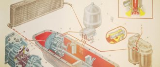
Engine starting system diagram:
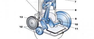
Starting system drive system
This mechanism transmits torque from the electric motor to the flywheel. A drive gear is installed on the armature shaft. The action of the electromagnetic switch causes the drive lever to engage the drive gear with the toothed rim of the flywheel (in this position, rotation is transmitted to the engine shaft). When the engine is started, the window clutch disengages and the drive gear now rotates to idle. Later, when the ignition is turned on, the drive gear disengages from the toothed rim.
Now let's look at the real mechanism: the window clutch transmits rotation in only one direction and is connected to the drive gear. The starter motor coupling has screw splines. There are also screw splines on the armature shaft. The drive gear is able to slide along them while rotating. Helical splines ensure smooth engagement of the drive gear with the toothed rim. After the toothed rim engages with the drive gear, the engine spins up. The drive gear rotates the toothed rim (while the window clutch operates). When the engine is running, the engine rotates the drive gear, while the window clutch is disengaged. The drive gear rotates at idle so as not to damage the electric motor.
Electromagnetic switch
Electromagnetic switch - causes the drive arm to move the drive gear and directs current to the electric motor.
Diagram of operation of the electromagnetic switch
There is a plunger in the center of the switch. The plunger performs two functions: it moves an actuator arm connected to one end of the plunger, and also actuates the main contacts through a contact plate connected to its other end. The plunger is surrounded by a retractor winding, which pulls the plunger to the main contacts. On top of the retractor winding there is a holding winding that holds the plunger against the contacts. When you turn the ignition key, an electric current passes through the retractor and retainer windings, creating a magnetic field. This field moves the plunger to the right. As a result, the contact plate closes the main contacts. Now terminal 30 is connected to terminal C connected to the motor. A powerful current is supplied to the starting electric motor, at the same time, the drive lever engages the drive gear and it begins to spin the engine.
How does an electromagnetic switch work?
The retracting and holding windings are fixed to the switch body. The contact plate is located at the end of the plunger opposite the main contact. The retracting and holding windings are placed around the plunger, which is pressed by the return spring. After the engine starts, the return spring moves the drive gear to its original position.
Electrical diagram of the engine starting system
The positive pole of the battery is connected to terminal 30 and the ignition switch. Terminal C is connected to the field windings and the armature winding, grounded to the housing and then connected to the negative pole of the battery. All connections are made with a powerful cable that can withstand high current. Terminal 50 is connected to the positive pole of the battery through the ignition switch.
When you turn the ignition key, the current first passes through the pull-in and holding windings, then through the field and armature windings, and finally into the ground. Since the resistance of the armature and field windings is very low, almost all of the battery voltage falls on the pull-in and holding windings. The field arising in them moves the plunger to the right. The drive lever connected to the plunger moves the coupling to the left, while simultaneously turning it on the screw splines of the armature. Together with the engagement of the drive with the flywheel ring gear, the main contacts are temporarily closed. When the main contacts are closed by the contact plate, the field and armature windings are powered directly from the battery. After closing the contacts, the potentials of terminals C and 50 are equalized. The retractor winding no longer acts on the plunger. And it is held in the same position only by the magnetic field of the holding winding. When the ignition key is turned off after starting the engine, the main contacts remain closed. But now the current from the main contacts enters the pull-in winding in such a way that its magnetic field is opposite to the field holding the winding. Both magnetic fields cancel each other out. Now the return spring moves the plunger to its original position and opens the main contacts. At the same time, the drive gear disengages and returns to its original position.
Source
Car starting system purpose and technical requirements
The vehicle starting system is used for automatic remote engine starting and consists of a starter, an engagement mechanism, an electromagnetic relay and an auxiliary relay. The main technical requirements for the starting system are:
- reliable operation of the starter at 40-50 thousand kilometers;
- reliable operation of the starter when starting up to a temperature of 15°C
- reliable operation of the engagement mechanism and electromagnetic relays;
The electrical wiring for the starter and relay power supply is securely attached. Starters, for example, for cars ST 29.3708, ST 230-62, for trucks ST 142 B, ST 130 B consume current from 550 to 850 A with a rotation speed of up to 5 thousand min-1 with a subsequent reduction in current to 80-100 A.
Types of remote start system
Today there are two types of remote engine starting in a car.
- Driver controlled starting system. This scheme is the most optimal and safe. But it is feasible only if the owner of the car is at a short distance from the car (within 400 meters). The driver himself controls the start of the engine by pressing a button on the key fob or in an application on his smartphone. Only after receiving a command from the driver does the engine begin to operate.
- Programmed engine activation depending on the situation. If the driver is far away (for example, the car was left overnight in a paid parking lot, and not in the yard near the house), the start of the internal combustion engine can be set to certain conditions: start at a given time;
- when the engine temperature drops to certain values;
- when the battery charge level decreases, etc.
What is
Modern cars have an electric engine starting system. It is also often called a starter starting system. Simultaneously with the rotation of the crankshaft, the timing, ignition and fuel supply systems are switched on. The air-fuel mixture is burned in the combustion chambers and the pistons rotate the crankshaft. After reaching a certain crankshaft speed, the engine begins to work independently, by inertia.
Engine starting
To start the engine, you need to reach a certain crankshaft speed. This value differs for different types of engines. For a gasoline engine, the minimum required is 40-70 rpm, for a diesel engine - 100-200 rpm.
At the initial stage of the automotive industry, a mechanical starting system using a crank was actively used. It was unreliable and inconvenient. Now such solutions have been abandoned in favor of an electric starting system.
Car starter
Automotive internal combustion engines require starting assistance.
Engine starting systems consist of the following components:
- DC motor (starter);
- Switching equipment and control units;
- Accumulator battery;
- Wiring.
The starter speed, much higher than the engine crankshaft speed, is matched to the engine crankshaft speed through a gearbox with a suitable gear ratio (1/10 - 1/20) located between the starter gear and the engine flywheel ring gear. A small starter is able to develop the necessary speed for reliable engine starting (spark ignition engines require 60-100 min -1; diesel engines - 80-200 min -1). Compression and decompression in the cylinders means that the torque required to turn the crankshaft varies significantly, causing the instantaneous rotational speed to also vary significantly. In Fig. “ Engine RPM and Cold Start Current Graph ” shows a typical graph of engine RPM and starter current during a cold start.
The starter itself must meet the following technical requirements:
- Ready to work at any time;
- Sufficient starting power at different temperatures;
- Long service life;
- Reliability of the design;
- Light weight and compact dimensions;
- No maintenance required.
Starter design features
To create the required fuel-air mixture for spark-ignition engines and automatic ignition temperature for diesel engines, the starter must rotate the internal combustion engine crankshaft at a certain minimum speed. Engine speed is highly dependent on engine type, displacement, number of cylinders, compression ratio, friction losses, additional loads generated by engine operation, fuel management system, type of oil used and ambient temperature.
In general, starting torque and starting speed with decreasing temperature require a gradual increase in starting power. However, the power generated by the starting battery decreases with decreasing temperature, as its internal resistance increases. This conflicting relationship between electrical load requirements and available power means that the worst operating condition for an internal combustion engine starting system is a cold start.
Due to the large current consumed by the starter, the voltage drop on the supply wires significantly affects the characteristics of the starter.
Classification of engine starting systems
The automatic engine starting system has a rated power of up to 2.5 kW at a rated voltage of 12 V. It can start spark-ignition engines with a displacement of up to 7 liters and diesel engines with a displacement of up to 3 liters.
Engine starting system device
The engine starting system includes the following key elements:
- control mechanisms (ignition switch, remote start, Start-Stop system);
- accumulator battery;
- starter;
- wires of a certain cross-section.
Engine starting circuit
The key element of the system is the starter, which, in turn, is powered by the battery. This is a DC motor. It creates torque, which is transmitted to the flywheel and crankshaft.
Turning on the starter
In a traditional start, the driver connects battery voltage (ignition key in start position) to the starter relay. The relay current (about 30 A for cars, about 70 A for trucks) creates a certain power in the relay. It pushes the starter gear against the flywheel ring gear and activates the primary starter current (200-1000 A for cars, about 2000 A for trucks).
The starter is turned off when the ignition switch is opened, interrupting the voltage supply to the starter relay.
Tips and tricks
The engine start button works in such a way that the driver presses it and holds it for the required time to start. During this period of time, the starter rotates the crankshaft, resulting in the engine starting. Then the button can be released.
Note that when choosing a “start-stop” engine start button, a number of certain nuances should be taken into account. One of these points is the issue of fixing this button. The optimal option is when, after pressing, the contacts are closed, and when released, they open. If the button has a lock, then after starting the engine, you will need to quickly press it again to open the contacts.
As for the button itself, there are many available solutions available for free sale, which differ in quality, price and other characteristics. These buttons can be backlit and made of plastic or metal.
For these reasons, it is worth considering when choosing:
- a strong current will be supplied to the button;
- the solution will be constantly used;
Taking into account these operating features, it is better to choose an engine start button with a high-quality external coating (for example, chrome plating). Such a product will have abrasion resistance to maintain an acceptable appearance
You also need to understand that cheap offers can burn out after just a few clicks, so this aspect should be given special attention
Starting motor device
The design of the PD consists of:
- Power systems.
- Starting motor gearbox.
- Crank mechanism.
- Ostova.
- Ignition systems.
- Regulator.
The engine frame consists of a cylinder, crankcase and cylinder head. The crankcase parts are connected to each other by bolts. The pins outline the center of the starting motor. The transmission gears are protected by a special cover and are located in the front part of the crankcase, the cylinder is in the upper part. Double cast walls create a jacket into which water is supplied through a pipe. Wells connected by two purge ports allow the mixture to enter the crankcase.
By design, starting engines are two-stroke starting engines paired with modified diesel engines. The engines are equipped with a single-mode centrifugal regulator directly connected to the carburetor. The stability of the crankshaft, as well as the opening and closing of the throttle valve, are adjusted automatically. Despite its low power (only 10 horsepower), the PD can rotate the crankshaft at a speed of 3500 rpm.
Features of battery operation
Successful engine starting will depend on the condition and power of the battery. Many people know that such indicators as capacity and cold cranking current are important for batteries. These parameters are indicated on the marking, for example, 60/450A. Capacity is measured in Amp-hours. The battery has low internal resistance, so it can deliver large currents for a short time, several times its capacity. The specified cold cranking current is 450A, but subject to certain conditions: +18C° for no more than 10 seconds.
However, the current supplied to the starter will still be less than the specified values, since the resistance of the starter itself and the power wires is not taken into account. This current is called inrush current.
Reference. The internal resistance of the battery is on average 2-9 mOhm. The starter resistance of a gasoline engine is on average 20-30 mOhm. As you can see, for proper operation it is necessary that the resistance of the starter and wires be several times higher than the resistance of the battery, otherwise the internal voltage of the battery during startup will drop below 7-9 volts, and this should not be allowed. When current is applied, the voltage of a working battery drops to an average of 10.8V for a few seconds, and then recovers again to 12V or slightly higher.
The battery supplies starting current to the starter for 5-10 seconds. Then you need to pause for 5-10 seconds for the battery to “gain strength”.
If, after attempting to start, the voltage in the on-board network drops sharply or the starter cranks halfway, this indicates a deep discharge of the battery. If the starter makes characteristic clicks, then the battery is completely dead. Other reasons may include a broken starter.
Features of starting the engine in winter conditions
In winter it can be difficult to start the engine. The oil thickens, which means it is more difficult to turn it. The battery also fails frequently.
At sub-zero temperatures, the internal resistance of the battery increases, the battery drains faster, and is also reluctant to deliver the required starting current. To successfully start the engine in winter, the battery must be fully charged and not frozen. Additionally, you need to monitor the contacts on the terminals.
Here are some tips to help start your engine in winter:
Thousands of drivers start their engines every day and go on business. Getting started is possible thanks to the coordinated operation of the engine starting system. Knowing its structure, you can not only start the engine in a variety of conditions, but also select the necessary components in accordance with the requirements specifically for your car.
Which autorun block to choose
Before purchasing a unit, you need to determine what features you need and how much you are willing to pay for them. If you already have some kind of alarm system, it is advisable to find an autostart unit that is compatible with it. This will avoid serious alterations to the vehicle's electrical wiring. If you have an outdated alarm system installed, which only provides a sound signal when there is an attempt to break into or steal, then it makes sense to install an autostart combined with the alarm.
Blocks that expand the capabilities of alarms will cost significantly less than individual devices. For example, the Pandora RMD-8 relay module, compatible with most Pandora alarm systems, will cost 2-3 thousand rubles. The module provides reliable starting and control of the operation of both gasoline and diesel engines. It is connected to the vehicle's standard CAN bus, so no major wiring modifications are required.
More functional units with a GSM module will cost 5-10 thousand rubles. For example, the cost of the Starline M31 module is 8-10 thousand rubles. The module works both with Starline alarms and independently. When using the module independently, it to some extent performs the functions of a car alarm. Thanks to the built-in GPS unit, the module informs about the location of the car, turning the engine on and off, and allows audio and video monitoring of what is happening in the cabin. To control the module, use a phone, tablet or other device that works with the appropriate SIM card. The presence of three redundant module inputs allows you to connect door sensors, vibration sensors or other devices to them. The only drawback of GSM modules is the need to pay for traffic. If the module is used only in SMS exchange mode, then the monthly payment will be noticeably lower, but the functionality will also decrease. If the module operates in constant communication mode, then the payment will be higher, but the module itself will be able to perform a greater number of functions, including the ability to control the car in real time.
If you need a full-fledged alarm system with an autostart function, then Starline D94 GSM Slave is a good option. This alarm will cost 20-25 thousand rubles. The alarm is equipped with a built-in vibration, jacking and theft sensor. The alarm system supports the connection of a large number of third-party sensors, which improves security control. The built-in GSM module allows you to control the alarm not only using the standard key fob, but also through the corresponding application on your phone, smartphone or tablet. The alarm is installed on modern cars equipped with a CAN bus. The only drawback of the alarm is the lack of a GPS/GLONASS module, which makes it impossible to track the vehicle's location.
If for some reason the GSM module or alarm system is not suitable for you, pay attention to traditional devices that use a radio channel. For example, Starline A91 Dialog
The cost of the alarm is 6-9 thousand rubles. The key fob provides stable communication with the alarm system at a distance of up to 250 meters. All information about the condition of the car is transmitted to the key fob and displayed using an LCD indicator. The presence of additional executive channels allows you to connect various devices. For example, a mirror control module, a pre-heater or an electric drive that regulates the height or position of the seats.
Starter Interlock Switch (CLUTCH ENABLED)
This switch blocks the starter from turning on if the gear selector is not in the park or neutral position, or the clutch pedal is released.
Rice. Typical electrical engine starting circuit. Please note that at the first moment when turning the ignition key to the “start” position, voltage is applied simultaneously to both the pull-in winding and the holding winding of the traction relay. As soon as the contact disk of the electromagnet closes terminals B and M, current from the battery begins to flow through the starter winding
Observe how the interior lighting behaves when starting the engine.
When diagnosing the cause of a problem with normal engine starting, open the car door and watch how the brightness of the interior lighting bulbs changes.
The brightness of the lighting lamp depends on its supply voltage.
During normal starter operation, the brightness of the interior lighting decreases slightly.
If the brightness of the lighting does not change, then the cause of the problem is usually an open circuit in the starting system control circuit.
If the lighting almost or completely goes out, then the cause of the problem is most likely a short circuit or breakdown to ground in the starter field windings or a faulty battery.
Don't knock on the starter!
In the past, it was not uncommon to see a technician banging on the starter to try to figure out why it wasn't working. Frequently, shock loads caused alignment or displacement of the current collector brushes, rotor, and bearing shells. In many cases, after a blow to the starter, its performance was restored - even if only for a short time.
But the design of most modern starters uses permanent magnets, which are fragile and can break if the starter is hit. A broken magnet disintegrates into several weak magnets. In some of the first designs of permanent magnet starters, the magnets were glued to the stator housing. With a strong blow to the starter, these magnets shattered into pieces, which, when they hit the rotor or in the bearing sockets, rendered the starter completely unusable.
Source
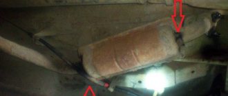
Exhaust system
Now that we know about a number of things we put (poured) into our car, let's take a look at the other things that come out of it. The exhaust system includes an exhaust pipe and a muffler. Without a muffler, you would hear the sound of thousands of small explosions from your exhaust pipe. The muffler dampens the sound. The exhaust system also includes a catalytic converter, which uses catalyst and oxygen to burn off any unused fuel and some other chemicals in the exhaust. Thus, your car meets certain European standards for air pollution levels.
What else is there besides all of the above in the car? The electrical system consists of a battery and a generator. The generator is connected to the engine by a belt and produces electricity to charge the battery. The battery provides a 12-volt charge of electrical energy that is available to everything in the car that needs power (ignition system, radio, headlights, windshield wipers, power windows, power seats, on-board computer and many more) through the vehicle's wiring.
Now we can say that you know everything about the basics of the main engine subsystems!
Electric starter[edit | edit code]
Electric car starter.
Starter relay (top left, black). Traction relay (solenoid, in the top center, small diameter, golden color). The silver case contains a lever transmission and an overrunning clutch. The electric motor is large in diameter, golden in color.
The most convenient way. When starting, the engine is spun by a brushed electric motor - a DC machine powered by a battery (after starting, the battery is recharged by a generator driven by the main engine). At low temperatures, commonly used acid batteries lose power, their starting capacity drops (mainly due to a decrease in the rate of chemical reactions), and the viscosity of the oil in the lubrication system increases. Therefore, starting the engine in winter is difficult and sometimes impossible. If there is an electrical network, in this case it is possible to start from a network starting device (virtually unlimited power).
Electric motors of automobile starters have a special design with four brushes, which allows increasing the rotor current and the power of the electric motor.
The principle of operation of an electric starter[edit | edit code]
When the starter is turned on, electric current (through the start relay, otherwise the contacts in the ignition switch will burn out) is supplied to the traction relay (solenoid). The solenoid core retracts and, through a linkage, engages the starter motor gear with the ring gear (large gear) of the flywheel. After this, the starter relay contacts close. A very large current (tens and even hundreds of amperes[2]) passes through this relay to the electric motor. After starting, the freewheel (Bendix) allows the engine flywheel and starter motor to rotate independently of each other. After turning off the starter, the starter parts return to their original state. On old cars (for example, GAZ-69, GAZ-63) there was no traction relay (solenoid), the driver turned on the starter with a pedal on the cabin floor[3].
The amount of electrical voltage on the starter[edit | edit code]
On cars with gasoline internal combustion engines, the on-board voltage is 12 volts, and the same electrical voltage is used at the starter. A number of cars produced in the first half of the 20th century used 6 volts.
On cars with powerful diesel engines, the on-board voltage is 24 volts. This is due to the fact that a diesel engine with a large displacement and a high compression ratio requires a powerful electric starter. Two 12-volt car batteries are installed, connected in series.[4]
With equal electrical power, when the electrical voltage doubles, the current decreases accordingly by half: P = I ⋅ U {displaystyle P=Icdot U} , where I {displaystyle I} is the current strength, and U {displaystyle U} is the voltage .
Increasing the voltage allows you to reduce the discharge current of the battery, as well as reduce unnecessary heating of the wires.
Passenger cars, minibuses and light trucks with diesel engines use 12-volt starters (this is quite enough).
Common problems and how to fix them
If the starting engine cannot be started, they diagnose the problem and try to fix it. The reason for this may be clogging of the main mechanisms and engine parts, which prevents fuel from entering the float chamber. This can be eliminated by cleaning all parts.
Lack of spark at the end of the plug may be another reason why the engine will not start. In this case, the wiring passing through the magneto is checked. The misaligned adjustment is corrected after starting and warming up the engine. An incorrectly set ignition timing may be one of the reasons that the PD does not start.
Incorrect engine operation can be caused by several reasons:
- The idle jet was clogged.
- The idle screw is incorrectly adjusted.
- The main jet is dirty.
- Incorrect ignition angle setting.
- Problems with opening the throttle valve.
- Pipeline clogged.
- Motor starting capacitor is clogged.
Rapid engine overheating can be eliminated by adding water, but there can be several reasons for heating - for example, clogging of the space between the head and the cylinder or the combustion chamber with carbon deposits. This can be eliminated by cleaning all mechanisms with the engine turned off. However, the reason for overheating of the launcher is not always the lack of water or contamination: it was initially designed for a maximum of 10 minutes of operation at a time. Longer use may result in accelerated wear.
Ignition, power supply and lubrication systems at startup[edit | edit code]
For engines with spark ignition, the problem of power supply to the ignition system at the time of start-up is also relevant. Automobile generators with independent excitation cannot operate without an external source of direct current, therefore, for example, IZH and Ural motorcycles do not start when the battery is discharged, although the start is carried out by a kick starter and not an electric starter. This problem is solved by using a generator with excitation from permanent magnets (as on the Minsk and Voskhod motorcycles) or magnetos, which provide current immediately, but such generators have less power. The problem becomes much less severe when using electronic ignition, but it is also unable to operate if the battery is completely discharged. This means that even with a rotating motor (for example, a towed car), there will be no spark.
In diesel engines, where in operating modes atomized fuel is ignited by air heated by compression in the cylinder, to simplify cold starts, glow plugs are often used - low-resistance spirals inside the combustion chamber, heated by current from the battery until the engine reaches stable operation.
In addition to problems with the energy of the ignition system, there is also a problem with mixture formation when starting a cold engine. At low temperatures, fuel evaporates poorly. To prevent the working mixture from becoming lean, various starting devices are introduced into the power system (an air damper in the carburetor; a float suppressor on old motorcycles; an additional fuel supply valve with a shutdown delay after starting) or the injection supply is increased. Unevaporated excess gasoline enters the cylinders in the form of droplets, which settle on cold internal surfaces. Fuel can “flood” the spark plug, causing current to leak through the wet plug insulator and thereby causing no spark breakdown or a significant weakening of the spark. Gasoline flowing down the cylinder walls washes away the oil film, which is already insufficient after parking, causing very noticeable additional wear on the CPG, even to the point of scuffing the pistons.
In modern cars, the manufacturer often provides a “purge” mode for the cylinders, in which the active supply of fuel stops, and the operation of the pistons frees the volume from excess fuel. To use this mode, you need to press the gas pedal all the way and start cranking the starter. Some motorcycles have a decompressor valve on the cylinders for this purpose.
To start the engine at low temperatures, various “starting fluids” are used based on ether, known for its volatility (boiling point 34 °C) and ease of ignition. This liquid is injected from an aerosol can into the intake manifold immediately before attempting to start. On northern and military versions of some cars, the ether injection system is installed as standard at startup.
Problems also arise in the lubrication system when starting, especially when the engine is cold. At the first revolutions, engine parts operate virtually without forced lubrication until the oil supply channels are filled and oil mist forms in the crankcase. The replaceable oil filter has a check valve that prevents oil from draining from the channels when parked; Timely replacement of the filter is also important from the point of view of preserving the properties of the valve rubber. In cold weather, the oil thickens, and the pump does not immediately begin to supply it in full. Therefore, scuffing of the main rubbing pairs may occur when the gas is suddenly applied immediately after the start. To avoid this phenomenon, on large and complex engines, a preliminary booster electric pump is sometimes used, operating in parallel with the main one. Conventional engines of cars and motorcycles should simply be started in accordance with the manufacturer’s instructions, and if there are problems, do not “accelerate” as soon as you “catch it”, but adjust the engine and eliminate any detected faults.
Checking the gaps between the electrodes
The spark plug is unscrewed and the hole is closed with a plug. Carbon deposits on a candle are removed by placing it in a bath of gasoline for several minutes. The insulator is cleaned with a special brush, the housing and electrodes with a metal scraper. The gap between the electrodes is checked with a feeler gauge: its value should be in the range of 0.5-0.75 millimeters. The gap is adjusted by bending the side electrode if necessary.
The serviceability of the spark plug is checked by connecting it to the magneto with wires and turning the crankshaft until a spark appears. After checking and servicing, the spark plug is returned to its place and tightened.
Checking the gap between the breaker contacts
The breaker parts are wiped with a soft cloth soaked in gasoline. The deposits formed on the surface of the contacts are cleaned off with a needle file. The engine crankshaft rotates until the contacts open to maximum. The gap is measured with a special feeler gauge. If there is a need to adjust the gap, use a screwdriver to loosen the screw and the rack fastening. The cam wick is moistened with a few drops of clean engine oil.