Gasoline engine injection systems
Depending on the method of formation of the fuel-air mixture, the following injection systems for gasoline engines are distinguished:
- central injection system;
- distributed injection system;
- direct injection system.
Central and distributed injection systems are pre-injection systems, i.e. injection into them is carried out before reaching the combustion chamber - in the intake manifold.
Central injection ( mono injection
) is carried out by a single injector installed in the intake manifold. Essentially it is a carburetor with a nozzle. Currently, central injection systems are not produced, but are still found on passenger cars. The advantages of this system are simplicity and reliability, but the disadvantages are increased fuel consumption and low environmental performance.
Distributed injection system ( multipoint injection system
) involves supplying fuel to each cylinder with a separate injector. The formation of the fuel-air mixture occurs in the intake manifold. It is the most common injection system for gasoline engines. It is distinguished by moderate fuel consumption, low levels of harmful emissions, and low requirements for fuel quality.
The direct injection system is promising. Fuel is injected directly into the combustion chamber of each cylinder. The system allows you to create the optimal composition of the fuel-air mixture in all engine operating modes, increase the compression ratio, thereby ensuring complete combustion of the mixture, saving fuel, increasing engine power, and reducing harmful emissions. On the other hand, it is distinguished by its complex design and high operational requirements (it is very sensitive to the quality of the fuel, especially to its sulfur content).
Gasoline engine injection systems can be mechanically or electronically controlled. The most advanced is electronic injection control, which provides significant fuel savings and reduced emissions.
Fuel injection in the system can be carried out continuously or pulsed ( discretely
). Promising from an economical point of view is pulsed fuel injection, which is used by all modern systems.
In an engine, the injection system is usually combined with the ignition system and forms a combined injection and ignition system (for example, Motronic, Fenix systems). The coordinated operation of the systems is ensured by the engine management system.
Carburetor power systems
Let us first consider carburetor power systems, which were widespread until recently. They are simpler and cheaper than injection ones, do not require highly qualified maintenance during operation, and in some cases are more reliable.
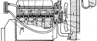
The fuel supply system for a carburetor engine includes a fuel tank 1, coarse 2 and fine 4 fuel filters, fuel pump 3, carburetor 5, intake pipe 7 and fuel lines. When the engine is running, fuel from tank 1 is supplied via pump 3 through filters 2 and 4 to the carburetor. There it is mixed in a certain proportion with air coming from the atmosphere through the air cleaner 6. The combustible mixture formed in the carburetor enters the engine cylinders through the intake manifold 7.
Fuel tanks in power plants with carburetor engines are similar to the tanks of diesel power systems. The only difference between gasoline tanks is their better sealing, which prevents gasoline from leaking even when the vehicle overturns. To communicate with the atmosphere, two valves are usually installed in the filler cap of the tank - inlet and outlet. The first of them ensures that air enters the tank as fuel is consumed, and the second, loaded with a stronger spring, is designed to communicate the tank with the atmosphere when the pressure in it is higher than atmospheric (for example, at high ambient temperatures).
Filters for carburetor engines are similar to those used in diesel power systems. Plate-slot and mesh filters are installed on trucks. For fine cleaning, cardboard and porous ceramic elements are used. In addition to special filters, individual units of the system have additional filter meshes.
The fuel priming pump is used to force gasoline from the tank into the carburetor float chamber. On carburetor engines, a diaphragm-type pump driven by a camshaft eccentric is usually used.
Depending on the operating mode of the engine, the carburetor allows you to prepare a mixture of normal composition (a = 1), as well as lean and enriched mixtures. At low and medium loads, when it is not necessary to develop maximum power, you should prepare it in the carburetor and feed a lean mixture into the cylinders. For heavy loads (their duration of action is usually short), it is necessary to prepare an enriched mixture.
Rice. Diagram of the fuel supply system for a carburetor engine: 1 - fuel tank; 2 — filter with fuel purification pipe; 3 — fuel priming pump; 4 — fine filter; 5 - carburetor; 6 — air cleaner; 7 - intake manifold
In general, the carburetor includes a main metering and starting device, idle and forced idle systems, an economizer, an accelerator pump, a balancing device and a maximum crankshaft speed limiter (for trucks). The carburetor may also contain an econostat and a height corrector.
The main metering device operates in all main engine operating modes in the presence of vacuum in the mixing chamber diffuser. The main components of the device are a mixing chamber with a diffuser, a throttle valve, a float chamber, a fuel nozzle and spray tubes.
The starting device is designed to ensure the start of a cold engine, when the rotation speed of the crankshaft cranked by the starter is low and the vacuum in the diffuser is low. In this case, for a reliable start, it is necessary to supply a highly enriched mixture to the cylinders. The most common starting device is a choke valve installed in the carburetor intake pipe.
The idle system is used to ensure engine operation without load at a low crankshaft speed.
The forced idle system allows you to save fuel while driving in engine braking mode, that is, when the driver, with the gear engaged, releases the accelerator pedal connected to the carburetor throttle valve.
We recommend: Shelf life of engine oil in the canister and engine
The economizer is designed to automatically enrich the mixture when the engine is running at full load. In some types of carburetors, in addition to the economizer, an econostat is used to enrich the mixture. This device supplies additional fuel from the float chamber to the mixing chamber only when there is a significant vacuum in the upper part of the diffuser, which is only possible when the throttle valve is fully open.
The accelerator pump provides forced injection of additional portions of fuel into the mixing chamber when the throttle valve is sharply opened. This improves the throttle response of the engine and, accordingly, the vehicle. If there were no accelerator pump in the carburetor, then with a sharp opening of the damper, when the air flow rate increases rapidly, due to the inertia of the fuel, the mixture would at first become very lean.
The balancing device serves to ensure stable operation of the carburetor. It is a tube connecting the carburetor intake pipe to the air cavity of a sealed (not communicating with the atmosphere) float chamber.
A maximum engine speed limiter is installed on truck carburetors. The most widely used limiter is the pneumatic centrifugal type.
What is a direct injection system and how does it work?
Central injection system Mono Jetronic
Direct injection is considered one of the most modern types of fuel transportation in gasoline engines. The direct supply system is considered an injection circuit for the transfer of fuel for gasoline internal combustion engines with direct injection, in which the injectors are located in the cylinder head, and transportation is direct. That is, gasoline is supplied under a certain pressure into the combustion chamber of each cylinder, as opposed to the standard distributed injection scheme, where injection takes place in the intake manifold.
The idea presented by the developers contributed to the emergence of a direct fuel injection system, which became a new generation. As a rule, direct fuel injection is used in the most modern two-pin and four-pin internal combustion engines.
Direct fuel injection has the main advantage of reducing fuel costs by operating the engine on combustible mixtures that are quite lean in composition. Until today, transportation of fuel was not so common, and this was due to the following reasons:
- More time was spent on fuel formation;
- The generally accepted scheme for transportation into the intake manifold today greatly simplifies the design of the injector itself;
- The design of the block head is greatly simplified.
The operation of the circuit as “direct fuel injection” is based on transporting fuel directly into the combustion chamber of the engine. Before understanding the operating principle of the direct fuel supply system, it is necessary to understand its elements. The direct fuel supply circuit device includes a high-pressure pump (HPF), a fuel rail, injectors, a fuel pressure regulator, a safety valve and a high-pressure sensor.
The main function of the injection pump is to supply fuel to the ramp, and then to the injectors under high pressure, corresponding to the needs of the engine. The design of the injection pump is based on several plungers. The high pressure pump itself begins to function with the help of the intake valve camshaft. The pressure regulator ensures a dosed supply of fuel to the injection pump, in accordance with the injectors. The regulator is located in the injection pump. The main function of the fuel is to distribute the mixture among the injectors and prevent pulsation of liquids in the circuit. The safety valve performs the protective function of the injection system elements from extreme pressures that arise during the temperature expansion of the mixture.
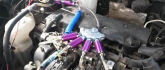
injection pump
Thanks to the signals coming from the high pressure sensor, the engine management unit can regulate the rail pressure.
Basic operating modes of direct fuel injection
Lean mode is used when the engine load is at a minimum level, while driving at reduced or constant speed. The standard or stoichiometric ratio of gasoline and air in the combustion chamber, which is necessary for normal ignition and combustion of gasoline, is considered to be 14/7/1. Although if the engine speed gradually or quickly decreases, then it can be absolutely harmlessly changed to reduce the amount of fuel. That is, in this mode, the air fraction can reach 65 degrees.
The standard mode is used during uniform vehicle movement with a constant load on the vehicle engine. In the presented mode, fuel is mixed with air in ideal proportions, and this will contribute to its complete combustion. During operation in the forced maintenance mode, the level of the fuel mixture is slightly exceeded. Thanks to this, maximum power is developed, and this is quite useful, for example, for an overloaded vehicle that is moving uphill.
Operating principle and device
If previously forced fuel supply was carried out only in diesel units, then a modern gasoline engine is also equipped with a similar system. Depending on the type, its device will include the following elements:
- A control unit that processes signals received from sensors. Based on this data, it gives commands to the actuators about the time of spraying gasoline, the volume of fuel and the amount of air.
- Sensors installed near the throttle valve, in the catalyst area, on the crankshaft, camshaft, etc. They determine the quantity and temperature of incoming air, its amount in the exhaust gases, and also record various operating parameters of the power unit. Signals from these elements help the control unit regulate fuel injection and air supply to the desired cylinder.
- The injectors spray gasoline either into the intake manifold or directly into the cylinder chamber, as in a diesel unit. These parts are located in the cylinder head near the spark plugs or on the intake manifold.
- A high-pressure fuel pump that creates the necessary pressure in the fuel line. In some modifications of fuel systems, this parameter should be much higher than the cylinder compression.
The system operates according to a principle similar to its carburetor counterpart - at the moment when an air flow and an injector enter the intake manifold (in most cases, their number is identical to the number of cylinders in the block). The first developments were of the mechanical type. Instead of a carburetor, they had one nozzle installed, which sprayed gasoline into the intake manifold, thanks to which the portion burned more efficiently.
This was the only element that was powered by electronics. All other actuators were mechanical. More modern systems operate on a similar principle, only they differ from the original analogue in the number of actuators and their installation location.
Different types of systems provide a more homogeneous mixture, so that the vehicle uses the full potential of the fuel, and also meets more stringent environmental requirements. A pleasant bonus to the operation of electronic injection is the efficiency of the vehicle with the effective power of the unit.
If in the first developments there was only one electronic element, and all other parts of the fuel system were of a mechanical type, then modern engines are equipped with fully electronic devices. This allows for more accurate distribution of smaller amounts of gasoline with greater efficiency from its combustion.
Many motorists are familiar with the term naturally aspirated engine. In this modification, fuel enters the intake manifold and cylinders due to the vacuum formed when the piston approaches the dead bottom point on the intake stroke. All carburetor internal combustion engines operate on this principle. Most modern injection systems work on a similar principle, only spraying is carried out due to the pressure created by the fuel pump.
Diesel device
Start-stop system: what is it and how does it work?
However, some additional elements are still present here. For example, the so-called high-pressure fuel pump, or high pressure fuel pump, has found widespread use on diesel engines. It receives signals from the control unit and sends a powerful jet of diesel fuel to the injector, thereby powering the engine. The nozzle is made of reinforced alloys, since ultimately the load on it is colossal.
What does this give? Firstly, the especially strong alloy of the power supply system allows the part to withstand significant temperature overloads. Secondly, this guarantees the longevity of the fuel system, since its repair is usually extremely expensive for owners.
The second thing you need to pay attention to is that so-called glow plugs are used here, due to which the injection system operates. The principle of their operation is not to ignite the prepared mixture, but to heat it at increased pressure when a signal is received from the control unit
The heating temperature is usually about 800 degrees, but in exceptional cases it reaches much higher, four-digit numbers.
Nozzle
Injecting water into the internal combustion engine
The fuel injector (injector) is an electronically controlled valve. The fuel supply to this valve is provided by the fuel pump. The nozzle can open/close many times per second.
When the injector is energized, an electromagnet moves a piston, which opens a valve, causing fuel to be injected under pressure through a tiny nozzle. The nozzle is designed to spray fuel. A fine mist appears that burns easily.
The injectors are installed in the intake manifold in such a way that they spray fuel directly onto the intake valves. The tube that supplies fuel to each of the injectors at a certain pressure is called a fuel rail.
In order to determine the optimal amount of fuel, the engine control unit receives signals from many sensors. Let's look at the most important of them.
Injection engine design, main sensors
To select the optimal amount of fuel under various operating conditions, the engine ECU monitors the readings of various sensors. Here are just a few of the main ones:
- Mass air flow sensor (MAF). Tells the control unit the mass of air entering the engine.
- Oxygen sensor(s) (lambda probe). Controls the oxygen content in exhaust gases. Using the information received from it, the ECU can detect a rich or lean fuel mixture and make appropriate adjustments.
- Throttle position sensor. It monitors the position of the throttle valve (it affects the air supply to the engine), thanks to which the control unit can quickly respond to changes, increasing or decreasing fuel consumption as necessary.
- Coolant temperature sensor. Helps the ECU determine when the engine has reached optimal operating temperature.
- Voltage sensor. Monitors the voltage of the vehicle's on-board network. Depending on the sensor readings, the control unit can increase the engine idle speed if the voltage drops (this happens with high electrical loads).
- Manifold absolute pressure sensor. Analyzes the air pressure in the intake manifold. The amount of air entering the engine is a good indicator of how much power it produces. The more air entering the engine, the lower the manifold pressure. This indicator is used to determine the amount of energy produced.
- Crankshaft speed sensor. Crankshaft rotation speed is one of the factors influencing the calculation of the required pulse duration.
There are two main types of control for multiport injection systems: the fuel injectors can open simultaneously, or each of them can open only before the intake valve of the corresponding cylinder opens (this is called sequential multiport fuel injection).
The advantage of sequential fuel injection is that the system can respond to any driver input faster, since from the moment the action is performed, it only waits for the next opening of the intake valve. The system does not need to wait for the motor to rotate completely. We were able to figure out how the injector works, but who is in charge of all this?
Features of the system, its components
If you look at the Common Rail device in general, you will find a very strong similarity with injection gasoline power systems, especially direct injection. In fact, the designers simply borrowed all the positive qualities that the injector has and transferred them to a diesel unit, but taking into account the operating characteristics of this type of engine.
The difference between a diesel engine and a gasoline engine
The peculiarity of this system, in relation to the classical mechanical one, lies in the preliminary accumulation of fuel pressure before supplying it to the cylinders. Hence the name – battery fuel system.
As before on diesel engines, the power system is divided into two circuits - low and high pressure. Additionally, an electronic part was added to the Common Rail design, which monitors and controls the executive part.
Low pressure circuit
This component has remained virtually unchanged structurally. It includes:
- tank,
- filter elements (coarse and fine);
- fuel pump;
- fuel pipelines.
Low pressure circuit
Additionally, this circuit includes some more parts - a fuel cooler and heater, as well as a cut-off valve. These components are discussed below.
High pressure circuit
But this contour has structurally changed significantly, since new components have been added to it. The device of this part includes:
- injection pump;
- high pressure line;
- central main pipeline (ramp);
- nozzles;
- pressure sensor and valve.
High pressure circuit
The essence of this design is that the high-pressure pump does not pump fuel to each injector separately, as was the case in a mechanical system, but pumps it into the main pipeline (ramp). And from there it is supplied to the injectors.
The use of a ramp in the design makes it possible to maintain the diesel fuel pressure before supply at the required value, while the engine speed does not have any effect on it. This, in turn, has a positive effect on the fuel supply process under different operating modes of the engine.
The main working elements in this circuit, as before, are the injection pump and injectors.
The pump has a mechanical drive, and the number of plunger pairs that create pressure can vary from 1 to 3. It is noteworthy that in such a pump, since there is no need to pump for each nozzle, the plunger pairs can be turned off in some modes.
But the injectors have changed in design. Common Rail uses electrohydraulic injectors equipped with electromagnetic or piezoelectric control valves. Their use made it possible to provide multiple injections, increasing the efficiency of the power plant.
Electronic component
As for the electronic part, it is almost completely identical to that used on injection engines. That is, it consists of an electronic control unit and a number of sensors:
- pressure in the main pipeline;
- crankshaft rotation speed;
- accelerator (gas pedal) position;
- air flow;
- lambda probe;
- diesel fuel and air temperatures.
Some engines use a number of other sensors. The purpose of the electronic part is identical to a gasoline engine. Sensors transmit information about the operation of power plant systems and mechanisms and a number of other parameters. The unit compares the incoming data with tabular data stored in memory, and based on this it sends an impulse to trigger the injectors.
Electronic control unit
No forced gasoline supply system works without an electronic control unit. This is a microprocessor into which the program is flashed. The software is developed by the automaker for a specific car model. The microcomputer is configured for a certain number of sensors, as well as a specific operating algorithm in case a sensor fails.
The microprocessor itself consists of two elements. The first one stores the main firmware - manufacturer settings or software that is installed by the technician during chip tuning (why it is needed is described in another article ).
The second part of the ECU is the calibration block. This is an emergency circuit that is configured by the motor manufacturer in case the device does not detect a signal from a certain sensor. This element is programmed for a large number of variables, which are activated when specific conditions match.
Given the complexity of communication between the control unit, its settings and sensors, you should be attentive to the signals that appear on the instrument panel. In budget cars, when a problem occurs, the engine icon simply lights up. To identify a malfunction in the injection system, you will need to connect the computer to the service connector of the computer and carry out diagnostics.
To facilitate this procedure, more expensive cars are equipped with an on-board computer that independently performs diagnostics and issues a specific error code. The decoding of such service messages can be found in the vehicle service book or on the manufacturer’s official website.
Types of injection systems on gasoline internal combustion engines
The following fuel supply systems are used on gasoline engines: central injection (mono injection), distributed injection (multipoint), combined injection and direct injection.
Central injection
The fuel supply in the central injection system occurs through a fuel injector, which is located in the intake manifold. Since there is only one nozzle, this injection system is also called mono-injection.
Systems of this type have lost their relevance today, so they are not provided in new car models, however, they can be found in some older models of some car brands.
The advantages of mono injection include reliability and ease of use. The disadvantages of such a system are the low level of environmental friendliness of the engine and high fuel consumption.
Distributed injection
The multipoint injection system supplies fuel separately to each cylinder, equipped with its own fuel injector. In this case, fuel assemblies are formed only in the intake manifold.
Currently, most gasoline engines are equipped with a distributed fuel supply system. The advantages of such a system are high environmental friendliness, optimal fuel consumption, and moderate requirements for the quality of fuel consumed.
Direct injection
One of the most advanced and progressive injection systems. The operating principle of such a system is the direct supply (injection) of fuel into the combustion chamber of the cylinders.
The direct fuel supply system makes it possible to obtain a high-quality fuel assembly composition at all stages of internal combustion engine operation in order to improve the combustion process of the combustible mixture, increase the operating power of the engine, and reduce the level of exhaust gases.
The disadvantages of this injection system include its complex design and high requirements for fuel quality.
Combined injection
This type of system combines two systems - direct and distributed injection. It is often used to reduce emissions of toxic elements and exhaust gases, thereby achieving high environmental friendliness of the engine.
All fuel supply systems used on gasoline internal combustion engines can be equipped with mechanical or electronic control devices, of which the latter is the most advanced, since it provides the best efficiency and environmental friendliness of the engine.
Fuel supply in such systems can be carried out continuously or discretely (pulse). According to experts, pulsed fuel supply is the most appropriate and effective and is currently used in all modern engines.
Design and principle of operation using the example of an electronic distributed injection system
Injection system design
In modern injection engines, each cylinder has an individual injector. All injectors are connected to the fuel rail, where the fuel is under pressure, which is created by an electric fuel pump. The amount of fuel injected depends on the duration of the injector opening. The opening moment is regulated by an electronic control unit (controller) based on the data it processes from various sensors.
The mass air flow sensor is used to calculate the cyclic filling of the cylinders. The air mass flow is measured, which is then recalculated by the program into cylinder cyclic filling. If a sensor fails, its readings are ignored and calculations are made using emergency tables.
The throttle position sensor is used to calculate the load factor on the engine and its change depending on the throttle valve opening angle, engine speed and cyclic filling.
The coolant temperature sensor is used to determine the temperature correction of fuel supply and ignition and to control the electric fan. If the sensor fails, its readings are ignored, the temperature is taken from the table depending on the engine operating time.
The crankshaft position sensor serves for overall system synchronization, calculating engine speed and crankshaft position at certain points in time. DPKV – polar sensor. If turned on incorrectly, the engine will not start. If the sensor fails, the system cannot operate. This is the only “vital” sensor in the system that makes it impossible for the vehicle to move. Failures of all other sensors allow you to get to the service center on your own.
The oxygen sensor is designed to determine the oxygen concentration in the exhaust gases. The information that the sensor provides is used by the electronic control unit to adjust the amount of fuel supplied. The oxygen sensor is used only in systems with a catalytic converter under Euro-2 and Euro-3 toxicity standards (in Euro-3 two oxygen sensors are used - before the catalyst and after it).
The knock sensor is used to monitor knock. When the latter is detected, the ECU turns on the detonation damping algorithm, quickly adjusting the ignition timing.
Listed here are only some of the basic sensors required for the system to operate. Sensor configurations on different vehicles depend on the injection system, toxicity standards, etc.
Based on the results of polling the sensors defined in the program, the ECU program controls actuators, which include: injectors, fuel pump, ignition module, idle speed regulator, canister valve for the gasoline vapor recovery system, cooling system fan, etc. (all again depends on the specific models)
Of all the above, perhaps not everyone knows what an adsorber is. The adsorber is an element of a closed circuit for recirculating gasoline vapors. Euro-2 standards prohibit contact of the gas tank ventilation with the atmosphere; gasoline vapors must be collected (adsorbed) and, when purged, sent to the cylinders for afterburning. When the engine is not running, gasoline vapors enter the adsorber from the tank and intake manifold, where they are absorbed. When the engine starts, the adsorber, at the command of the ECU, is purged with a flow of air sucked in by the engine, the vapors are carried away by this flow and are burned in the combustion chamber.
Actuators
When the electronic control unit has received data from all sensors (their number is stitched into the device’s program code), it sends the corresponding command to the system’s actuators. Depending on the modification of the system, these devices may have their own design.
Such mechanisms include:
- Sprayers (or nozzles). They are mainly equipped with a solenoid valve, which is controlled by an ECU algorithm;
- Fuel pump. Some car models have two. One supplies fuel from the tank to the injection pump, which pumps gasoline into the ramp in small portions. Thanks to this, sufficient pressure is created in the high-pressure line. Such pump modifications are only needed in direct injection systems, since in some models the injector must atomize the fuel in compressed air;
- Electronic module of the ignition system - receives a signal to form a spark at the right moment. In the latest modifications of on-board systems, this element is part of the control unit (its low-voltage part, and the high-voltage part is a dual-circuit ignition coil that creates a charge for a specific spark plug, and in more expensive versions an individual coil is installed on each spark plug).
- Idle speed regulator. It comes in the form of a stepper motor that regulates the amount of air passage in the throttle area. This mechanism is necessary to maintain engine idle speed when the throttle is closed (the driver does not press the gas pedal). This makes it easier to warm up a cooled engine - you don’t need to sit in a cold cabin in winter and turn on the gas so that the engine doesn’t stall;
- To regulate the temperature (this parameter also affects the supply of gasoline to the cylinders), the control unit periodically turns on the cooling fan installed near the main radiator. To maintain temperature while driving in cold weather and accelerate engine warm-up, the latest generations of BMW models are equipped with a radiator grille with adjustable fins (to prevent the internal combustion engine from overcooling, the vertical fins rotate, blocking the access of cold air flow into the engine compartment). These elements are also controlled by a microprocessor based on data from the coolant temperature sensor.