One of the main components of the power system of a diesel power plant is the pump, which supplies fuel under high pressure to the injectors. The full name is high pressure fuel pump (abbreviation: TNVD). In addition to diesel engines, such a pump is also used in gasoline units with an injection system, in which gasoline is supplied directly to the cylinders.
This unit of the power supply system has a rather complex design, since its task is not only to pump diesel fuel, but also to supply it to the injectors at strictly defined moments. In general, the functioning of the power plant directly depends on its operation.
Types of injection pump
There are several types of diesel fuel systems with different design features. This in turn affects the fuel injection pump device. So, on diesel engines the following pumps can be used:
- in-line;
- distribution;
- main lines.
Diesel engine injection systems
Despite the differences in design, they all use the same main working unit - a plunger pair. It is this that provides the pressure.
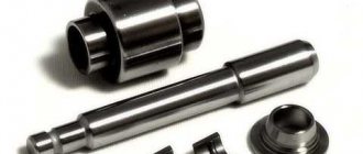
Main working node
This pair consists of two parts - a piston (aka plunger) and a sleeve (bushing). Since high pressure is created in the assembly, leaks between the components are not allowed. Therefore, the working surfaces of the piston and liner have a high degree of processing, which is why the pair is often called precision.
Plunger pair
The essence of the pair’s work is based on the reciprocating movement of the plunger inside the sleeve. In this case, through channels or valves, fuel enters the cavity above the plunger and is removed after compression.
Operation of the plunger pair
It all works like this: when the piston moves down, a channel or supply valve opens (depending on the injection pump device), and fuel is pumped into the cavity. When moving up, the supply stops (the channel or valve closes) and the plunger begins to compress the diesel fuel. When a certain pressure value is reached, the discharge valve opens and diesel fuel (already in a compressed state) enters the line leading to the injectors.
In general, the operation of the plunger pair itself is very simple, but there are many nuances and features, including design ones, that affect the functioning of this unit. Therefore, the operating principle of fuel injection pumps should be considered separately for each of these types.
Design features and operating principle of in-line injection pump
The in-line type is the “ancestor” of high-pressure pumps, since it was these fuel injection pumps that were used in the first diesel installations and it is still in use, although already limited.
Its peculiarity is that each injector has its own fuel section (with one working pair). All sections are placed in a row, hence the name of the injection pump type. A variation of it is a V-shaped pump, the sections of which are arranged in two rows. It is also worth noting that it is completely mechanical, and only in the latest modifications did they begin to use electromechanical fuel supply timing regulators.
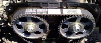
V-shaped injection pump
In it, the plungers are driven by a cam shaft, which is rotated by a drive from the crankshaft. In this case, the cams act on the pistons of the section not directly, but through roller tappets. The return movement of the plunger is ensured by a spring.
Interestingly, in this type of injection pump, regulation of the amount of fuel supplied to the injectors after compression is organized. To do this, two holes are made in the sleeve - inlet and outlet, with the first being located below the second. There is also a screw groove on the working surface of the piston. By rotating the liner relative to the plunger, it is possible to regulate the fuel portions.
And it all works like this: when moving up, the piston closes both holes, and fuel compression begins. But when raised to a certain level, the groove on the piston connects to the drain hole, which causes the pressure to drop as fuel begins to flow down the groove, and the discharge valve closes, stopping its pumping into the main line. By changing the location of the drain hole relative to the plunger, you can adjust the level of its coincidence with the groove.
For example, when the engine is running under load, it is necessary to supply more fuel. To do this, the bushing is rotated so that the hole with the groove coincides as late as possible, thereby increasing the portion of diesel fuel that passes through the discharge valve.
To rotate the sleeve, a rack is used, which has constant engagement with a gear sector mounted on the outer surface of the sleeve. Moreover, this rail acts on all fuel sections simultaneously, which ensures synchronized dosage regulation.
In-line injection pump
As already noted, the injection pump, in addition to compression, also ensures compliance with the injection timing. Moreover, in the in-line type this is organized very simply - the plunger pair is triggered exactly at the end of the compression stroke. But there is a very important point here - the larger the portion of injected fuel, the more time it takes to deliver it. That is, when the engine is running under load, injection should start earlier.
And this is provided by the injection timing advance regulator. In a fully mechanical pump, it is a centrifugal clutch mounted on the pump cam shaft.
The design of this coupling includes spring-loaded weights, which, due to centrifugal force, can diverge, overcoming the force of the springs. This discrepancy causes the cam shaft to change angle (rotate) relative to its drive. That is, the higher the rotation speed of this shaft, the greater the angle the weights will rotate it. As a result, the cam will approach the plunger pusher earlier and the injection start point will change.
Centrifugal clutch
The design also uses an electromechanical fuel supply timing regulator. In this design, electronics monitor the operating parameters of the power plant using sensors and, based on them, through actuators, control the angle at which diesel fuel begins to be supplied.
Mechanical fuel timing regulator
In-line pumps are highly reliable and unpretentious to fuel quality. But due to a number of disadvantages, including significant overall dimensions and a relatively slow response to changes in engine operating modes, the use of this type of injection pump is now limited. It is still used on heavy equipment; as for road transport, it has been replaced by other types of pumps.
Main causes of malfunctions
The injection pump is an expensive device that is very demanding on the quality of fuel and lubricants. If a car is operated on low-quality fuel, such fuel necessarily contains solid particles, dust, water molecules, etc. All this leads to failure of the plunger pairs, which are installed in the pump with a minimum tolerance, measured in microns.
Low-quality fuel easily damages the injectors, which are responsible for the process of atomizing and injecting fuel.
Common signs of malfunctions in the operation of fuel injection pumps and injectors are the following deviations from the norm:
- fuel consumption is noticeably increased;
- increased exhaust smoke is noted;
- during operation there are extraneous sounds and noise;
- power and output from the internal combustion engine drop noticeably;
- difficulty starting is observed;
Modern engines with fuel injection pumps are equipped with an electronic fuel injection system. The ECU doses the fuel supply to the cylinders, distributes this process over time, and determines the required amount of diesel fuel. If the owner notices the slightest interruptions in the operation of the engine, then this is an urgent reason to immediately contact the service. The power plant and fuel system are thoroughly examined using professional diagnostic equipment. During diagnosis, specialists determine numerous indicators, among which the most important are:
- degree of uniformity of fuel supply;
- pressure and its stability;
- shaft rotation speed;
Distribution type injection pump
The next stage in the development of diesel power systems was the use of distribution-type pumps.
The peculiarity of this type of injection pump is that the design uses only one fuel section, which provides supply to all injectors. It is noteworthy that there is only one section, but it can use a different number of plunger pairs - from 1 to 4.
There are several types of distribution injection pumps, differing in the characteristics of the operation of precision pairs and their drive. In general, all pumps of this type are divided into:
- end;
- rotary;
- with external drive (cam).
Note that the latter type, due to low reliability indicators, is not particularly widespread.
End type
Pumps with this drive are a fairly common option and are produced by many well-known manufacturers of fuel equipment for diesel engines.
High pressure fuel pump
The design of a high-pressure fuel pump with this type of drive implies the presence of only one precision pair, which simultaneously acts as a distributor - directs the compressed fuel to the required nozzle.
End view injection pump
The peculiarity of the work is that the piston not only performs reciprocating movement, it also rotates. To ensure the simultaneous execution of several movements, the design uses a special cam washer with rollers attached to it.
The essence of the work is very simple - this washer, due to the action of springs, is pressed against the stationary ring (rests against it with rollers). The ring has grooves for the rollers. When rotating, the rollers periodically fall into the existing recesses, which leads to the reciprocating movement of the washer itself, which is connected to the plunger, and it immediately rotates it.
Diesel engine power supply diagram
As the piston moves inside the bushing, the diesel fuel is compressed, and its rotation ensures the opening of one or another channel through which the fuel moves under pressure to the required nozzle.
The process of operation of the injection pump plunger
High pressure unit
This only described the operation of the fuel section. But the design of this pump includes a number of additional elements:
- fuel priming pump (rotary vane);
- feed timing advance regulator;
- dosing device (mechanical or electromagnetic);
If we consider all these additional devices, then the principle of their operation is not complicated.
The booster pump is located on the injection pump shaft and is a rotor with rollers installed in it. This rotor rotates in a stator, on the inner surface of which special grooves are made.
The main working mechanism of the injection pump
A fixed ring (to which a washer with rollers is pressed) acts as an injection advance regulator. By turning it around its axis, you can change the angle of rotation of the shaft at which the working pair is activated. This ring is driven by the actuators of the electronic fuel injection pump control unit.
Fuel dosage with a mechanical regulator is carried out by actuating a special clutch. In the electromagnetic type, the role of the dispenser is performed by a special shut-off valve, which, upon a signal from the control unit, shuts off the fuel supply to the line.
Rotary type
Another fuel injection pump of the distribution type, which has become quite widespread, has a so-called rotary drive (also known as an internal cam drive). This pump also has only one fuel section, which can use 2, 3 or 4 plunger pairs.
The couples in this type of pump are arranged radially. At the same time, the plungers move forward and move towards each other. The supra-plunger spaces are combined into a single cavity - a high-pressure chamber. There are no bushings in the plunger pairs as such. Their role is played by holes in the pump distributor shaft.
In general, the design of the fuel section includes a cam washer with grooves made on the inner surface. Inside this washer there is a distributor shaft with plungers installed in it. The pistons are driven through special roller shoes, the rollers of which are in constant contact with the working surface of the washer.
Cam double-plunger injection pump
The essence of the section’s operation is this: when the shaft rotates, the shoes repeat the shape of the washer’s surface. Contact with the surface protrusion leads to the shoes being pressed into the shaft, while they push the plungers (a translational movement occurs). The fuel that previously entered the high-pressure chamber is compressed and supplied to the distributor, where it is redirected to the required injectors.
But this is only the operating principle of the fuel section. The injection pump design also includes a fuel priming pump (rotary type), dosage and injection timing regulators, and an electronic control unit that regulates the operation of the pump depending on the operating mode of the power unit.
Distribution-type pumps are characterized by their compact size and fairly high generated pressure. But there are also disadvantages, the main one of which is the short service life of the plunger pairs.
Car device
The high-pressure fuel pump (HFP) is used to accurately dose fuel and supply it at a certain moment under high pressure to the injectors. Auto mechanics and drivers often refer to the high-pressure fuel pump as fuel equipment.
Currently, mechanically driven multi-plunger injection pumps are gradually giving way in diesel power systems to more advanced designs, such as computer-controlled pump-injector systems and rotary-type distribution pumps used in Common Rail power systems. Nevertheless, pumps of classical design are still widely used on many automotive engines.
Injection pump classification
High pressure fuel pumps are classified according to the following criteria:
by number of plungers:
- multi-plunger (there is one plunger for each cylinder);
- distribution (one plunger supplies fuel to several cylinders);
Multi-plunger injection pumps can be made with an in-line or V-shaped housing.
by type of plunger drive:
- mechanical;
- hydraulic;
- pneumatic;
according to the fuel dosing method:
- with regulation of the amount of fuel supplied per cycle (cut-off);
- with regulation of cyclic supply by throttling at the inlet (changing the filling of the above-plunger volume with fuel using a throttling device in the channel supplying fuel to the inlet window; used in distribution pumps).
Distribution injection pumps are divided into plunger and rotary.
***
Multi-plunger injection pumps with mechanical drive
In automobile diesel engines, multi-plunger pumps with a mechanical drive and regulation of the amount of fuel supplied by a cutoff have become widespread. Let us consider the design of such a pump using the example of a high-pressure fuel pump of the YaMZ-236 engine, which belongs to in-line plunger-type pumps and provides an injection pressure of 16 MPa (Fig. 1).
In the lower part of the pump housing 1, a cam shaft 12 with a gear 11 is mounted on two ball bearings. The cam shaft has profiled cams 19 according to the number of engine cylinders and an eccentric for driving the fuel pump, which is attached to the mating plane of the injection pump.
Roller pushers 18 are installed in the housing partition opposite each cam. The axes of the rollers 15 with their ends fit into the grooves of the pump housing, preventing rotation of the pushers. Adjusting bolts 40 are screwed into the center of the pushers, on which the plungers of the pump sections rest. All sections are arranged in the same way, they are interchangeable, and their number is equal to the number of engine cylinders.
The pump section consists of a sleeve 35 with a plunger 6, a discharge valve 33 with a seat 34, a spring 32 and a stop 31, a fitting 7, a rotary sleeve 16 with a gear 4, a pusher 18 with an axis and a roller 15, a plunger spring 38 and support plates 28 and 39.
The plunger sleeve is fixed in the body with a locking screw. The plunger and its bushing form a so-called plunger pair. The plunger pair is made of chrome-molybdenum steel and hardened to high hardness. After finishing the selection process, the plungers and sleeves are assembled so as to ensure a gap of 5...2 microns in their mating. The discharge valve 33 and its seat 34 are manufactured with the same precision. Therefore, these parts are called precision, and they are not interchangeable.
The discharge valve seat is pressed to the plunger bushing by a threaded fitting 7 through a sealing copper gasket. A high-pressure tube is attached to the fitting, connecting the pump section to the nozzle. Cam 19, pusher 18 and spring 38 provide reciprocating movement of plunger 6.
The plunger sleeve 35 is fixed in the body with a locking screw 29. The rotary sleeve 16 is loosely placed on the sleeve, and the protrusions 17 of the plunger fit into the vertical grooves of the lower part of the sleeve. At the upper end of the rotary sleeve there is a gear ring 4, which engages with a gear rack (common to all sections), which can move along the injection pump body.
When the rack moves along the fuel injection pump body, the sleeve 16 rotates on the plunger sleeve and, acting on the protrusions 17 of the plunger, rotates it, as a result of which the amount of fuel supplied to the injectors changes. The stroke of the rack is limited by the locking screw 37, which fits into its longitudinal groove.
The rear end of the rack is connected to rod 10 of the crankshaft speed regulator installed in housing 9. The front end of the rack protruding from the pump is covered with a cap into which a screw stop 2 is screwed in, limiting the fuel supply when the vehicle is run in.
The position of the stop is adjusted at the manufacturer and sealed.
Fuel is supplied to the plunger pairs through channel 36, and discharged through channel 30, at the front end of which a bypass valve 5 is installed under a cap. If the pressure in the channels exceeds 0.16...0.17 MPa, the valve opens and bypasses part of the fuel into the tank. The air that has entered the pump channels is released through a hole closed with plug 8.
The pump is driven by a gear transmission from the engine crankshaft through a fuel injection advance clutch. The coupling consists of 23 driving and 26 driven coupling halves. On the driven coupling half there are two axles 27 with centrifugal weights 25 installed on them, in the cutouts of which springs 22 are installed. The springs rest on the axis 27 on one side, and on the supporting pins 21 of the driving half coupling 23 on the other. The clutch assembly mechanism is closed by a cover 24 , which is screwed onto the thread of the driven coupling half.
***
Design and operation of the pumping section of the injection pump
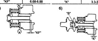
In Fig. Figure 2 shows the operation of the pumping section of the injection pump. The main parts of the fuel section are the plunger and its bushing. The bushing has two windows: the upper inlet 6 and the lower bypass 11. The inlet window is located in the cavity of the injection channel inlet, and the bypass is in the cavity of the exhaust channel. The plunger has a helical groove, the upper edge (cutting edge 5) of which is sharp. An axial drilling is made in the top of the plunger, which turns into a radial and helical groove.
Each section of the injection pump operates as follows. When the plunger is in the lower position (Fig. 2, a), fuel enters cavity A from the inlet window under pressure, which is created by the fuel priming pump. When cam 1 runs into pusher roller 2, the plunger begins to move upward, while part of the fuel exits back into the inlet window (Fig. 2, b).
When the plunger closes the inlet window (Fig. 2, c), the fuel in cavity A will be locked, which will lead to a sharp increase in pressure - this is the moment the injection begins. Further movement of the plunger leads to the opening of the discharge valve 9, and fuel flows to the nozzle - this is the moment the supply begins. The timing of the start of injection and the start of supply almost coincides.
With further movement of the plunger, the cut-off edge 5 will open the bypass window (Fig. 2,d), in which the pressure is 0.1...0.12 MPa. Fuel from cavity A, due to the pressure difference across the recess in the plunger and the shut-off groove, will begin to flow into bypass window 11. The pressure in cavity A will drop sharply. Discharge valve 9 will lower onto the seat. The fuel supply will stop, which will correspond to the end of supply (fuel cut-off). The plunger will continue to move further, but there will be no fuel supply, it will flow into the outlet port.
Common Rail injection pump
A slightly different type of high pressure pump is used in the Common Rail fuel system. The design of the injection pump is affected by the operating features of the system itself.
Single-plunger Common Rail injection pump
In this system, the injection is controlled and controlled by the computer, so the dosage and timing of fuel injection are not part of the pump's task. It has only one function - to pump fuel into the ramp (battery).
Therefore, the design of the injection pump is greatly simplified. In fact, the pump consists only of a shaft, plunger pairs (from 1 to 3) and valves - inlet and discharge. There are no regulators here as they are unnecessary.
Double plunger high pressure pump
Everything is simple here - the shaft rotates from the drive and the plungers constantly pump fuel into the ramp. This is all that is required from the injection pump.
How does a diesel engine fuel injection pump work?
Thanks to the use of proprietary Common Rail injection equipment, diesel fuel under pressure is supplied at a given moment to the spraying devices - nozzles. The process is controlled automatically. The main work of the fuel injection pump of a diesel engine is reduced solely to creating ultra-high pressure of diesel fuel. Complete combustion of fuel in the working cylinders of the engine ensures maximum power from a diesel engine that runs on diesel fuel.
The main requirement for injection pumps is the supply of diesel fuel under a pressure force of at least 150 megapascals (Mpa). The material used to manufacture the pump casing is high-quality aluminum alloy AL9. The fuel pump uses a so-called plunger pair - a set of parts consisting of a small cylinder of small diameter and a corresponding rod. The material used to manufacture these elements is high-strength steel 25Х5МА. In order to ensure maximum efficiency of the diesel engine, the production of these parts meets the requirement for ultra-high precision.
The volume of fuel supplied and the time it enters the combustion chamber are determined by the crankshaft rotation speed. When the driver presses on the gas, increasing the load, a calculated portion of diesel fuel is supplied to the engine, sufficient for the smooth functioning of the engine. The efficiency of the power unit depends on the serviceability of the high-pressure fuel pump, which means that the responsibility of the car owner includes timely maintenance and regular analysis of the condition and possible failures of all its elements, including the injection pump.