Ignition system specifications
Firing order 1—2—4—3
Sensor-distributor type…..19.3706
Alternation of sparks, hail…..After 90±1
Direction of rotation of the sensor-distributor roller (from the slider side)…..Counterclockwise
Ignition coil…..B116
Spark plugs….. A14VR
Gap between spark plug electrodes, mm…..0.8-0.95
Switch…..131.3734-01
Spark plug tip…..50.3707200 or 402.37707230
Resistor resistance in the tip is 4-7 kOhm
Technical aspects of winter operation
The most obvious and pressing question after a cold night outdoors is starting the engine. In this regard, the Gazelle car, even with its archaic ZMZ-402 engine, will give odds to more modern vehicles with electronic systems even at -30°C.
But provided that:
- spark plugs are adjusted and in good working order;
- high-voltage wires do not have cracks;
- the ignition system and carburetor are correctly adjusted;
- the cylinders of the 402 have normal compression ;
- The battery is fully charged .
The video above just shows the option of starting a car unprepared for winter. By the way, the Gazelle Business wiring diagram is also not immune from such cases. But how to make the start simpler and gentler for the car will be discussed further.
Fuel-air mixture
The first thing to remember is that the air-fuel mixture prepared by the carburetor on a cold engine has low volatility. Essentially, gasoline in the combustion chamber behaves like a liquid, and not like a vapor of gasoline and air, thereby making it difficult for ignition to begin.
The photo shows fuel combustion in a warmed-up car (a) and in an unheated one (b)
When the engine has been running for some time, then:
- gasoline entering the carburetor will heat up due to the heat of the operating internal combustion engine;
- a highly flammable air-fuel mixture will enter the combustion chamber;
- the engine will run stably.
Advice: Since car owners are unable to change the quality of gasoline, it is necessary to solve this problem on the car. Namely, to correctly adjust the operation of the ignition system elements.
How to do this, and how the Gazelle electrical wiring diagram works, is described in detail in our other publications.
Fuel ignition
In order to ignite “cold gasoline” in a cylinder, you need not just a spark on the electrodes of the spark plug, but a powerful electric discharge. The standard ignition system on the 402nd Gazelle is quite capable of providing such parameters, since this is provided for by design.
Classic ignition system ZMZ 402
The ignition system on the ZMZ 402 engine consists of:
- switch;
- ignition coils;
- distributor;
- candles;
- high voltage wires.
It is on their technical condition that the operation of the engine in the cold season will depend.
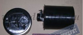
Ignition coil
An ignition coil is a transformer with a secondary winding wound on an iron core and a primary winding on top of it. The core with windings is installed in a sealed steel case filled with oil and closed with a high-voltage plastic cover.
Ignition Coil Maintenance
To protect against possible breakdown of the plastic cover, the ignition coil must be cleaned of dirt, dust and oil, and the high and low voltage wires must be checked for secure fastening.
Checking the condition of the coil
Malfunctions in the coil most often appear due to its overheating and operation with increased spark plug gaps.
Before removing the ignition coil for replacement, you should make sure that the wires are connected to the coil terminals in good condition and securely.
The coil should be checked on a special stand, model K-295.
A working coil should ensure uninterrupted sparking on a three-electrode needle gap with a spark gap of 7 mm at a frequency of 2500 min -1 of the sensor-distributor roller, no less.
If uninterrupted sparking is not ensured due to breakdown of the coil insulation, turn-to-turn short circuit, chips and cracks of the plastic cover, burnout of the cover, depressurization of the housing and oil leakage, the coil should be replaced.
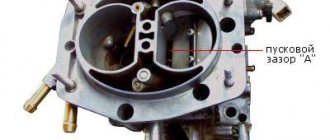
Installation of distributor with drive
Installation of the distributor with the drive is carried out as follows (all work is carried out with the power unit running):
- Turn the distributor counterclockwise.
- Be prepared for the engine speed to increase.
- If the car owner continues to crank the engine distributor, the power unit may stop working stably.
- When the engine speed drops, you need to turn the distributor clockwise.
Similar article What happens if you pour diesel oil into a gasoline engine
To test whether everything has been done correctly, it is recommended to sharply accelerate the car or, conversely, brake sharply and stand for a while. At the same time, the operation of the engine should be stable, and it should not stall.
Various circuits depending on the engine
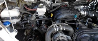
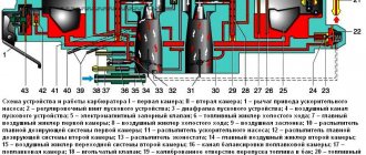
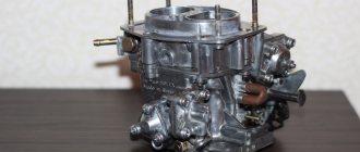
The ZMZ 402 carburetor engines were the very first to be installed on the Gazelle. For the operation of the internal combustion engine ignition system, it was necessary to supply power to the ignition coil, distributor and switch. The next engine to enter the series was the ZMZ 406, also in a carburetor version.
But it no longer had a coil, distributor and switch; instead, an electronic ignition control unit was installed.
Later, Gazelles began to be equipped with a ZMZ 405 injection engine, which instead of a carburetor had a distributed injection system.
This is what the ZMZ 405 engine looks like
Replacing wiring on a Gazelle car
The reasons causing the need to replace the electrical wiring according to the diagram in Gazelle cars are not only due to the overhaul of the power unit, but also:
- Due to natural wear and tear of wires;
- Delamination of insulation due to natural aging;
- Mechanical damage (kinks, scuffs);
- Short circuits in one or another electrical circuit;
- Oxidation of contacts and connectors.
Additional replacement materials
In addition to purchasing new electrical wiring, those corresponding to the motor used must also be replaced:
- High voltage wires;
- Electronic switch (in later versions of motors of the ZMZ-402 series);
- Ignition coil;
- Battery charge level relay;
- Fuse block contact group;
- Egnition lock.
Places requiring installation work
Laying the wiring harness is not a difficult task, especially since the places for their attachment to the frame are provided initially (gutters, service holes, etc.).
Gazelle interior with disassembled dashboard
However, according to complexity, replacement work is divided into areas of responsibility:
- Engine compartment;
- Vehicle interior;
- Rear part of the body.
The easiest part in terms of connection is the rear part of the car, where you only need to secure the harness and connect the rear lights and the fuel level sensor in the gas tank. The interior and engine compartment are more complex.
Electrical diagram and wiring faults of Gazelle 3302 and Business cars
Each car is equipped with an electrical diagram, which indicates all the devices and equipment used in the car, as well as the connection circuits. The functionality of the wiring is very important for any vehicle, since its damage can significantly complicate the operation of the car. What elements does the Gazelle electrical circuit include, what malfunctions are typical for it? Find answers to these and other questions below.
Wiring diagram for Gazelle 402 engine: do-it-yourself replacement
Having become an indispensable vehicle, the Gazelle with the 402 engine still requires attention over the years.
Electrical wiring is not listed among the parts subject to scheduled replacement, however, an electrical diagram is often required when carrying out repair work in the engine compartment.
Native 402 engine for Gazelle
Equipped with a ZMZ-402 carburetor engine, the car successfully exhausts its service life, and when the time comes for a major overhaul, many owners think not only about restoring, but also about reconfiguring its operation.
And since carburetor versions of power units have become a thing of the past, the question of the prospects for using a restored engine is urgent.
Electrical diagram of GAZ-3302, -2705 with engines ZMZ-402, UMZ-4215
GAZ-3302, -2705 - “Gazelles” of the earliest production were equipped with engines from the Zavolzhsky Motor Plant with a power of 100 hp. and Ulyanovsk plant, respectively 90 hp. The wiring of these models partially differs from models with injection engines in the part where the ignition systems are described and in additional sections of the control sensor circuits.
In order to download electrical circuit diagrams for GAZ-3302, -2705 , left-click on the picture, then click on the “full size” arrow and right-click “save as...”
- side turn signal indicator;
- turn signal indicator;
- headlight blocks;
- front position lamps;
- lamp (high-low) headlights;
- toggle switch for rear interior lighting (for vehicles with two-row seats);
- lighting of the engine compartment;
- lighting fixtures for the rear part of the cabin (for vehicles with two-row seats);
- cabin lighting lamp in the front;
- lampshades (canopy lamp for GAZ-2705 and GAZ-27057 with two-row seating) of the cargo compartment;
- starter relay;
- central block of fuse links;
- electric generator;
- starter location;
- battery;
- positive battery terminal switch;
- remote control button for battery switch;
- parking brake warning light relay;
- egnition lock;
- handbrake signal switch;
- brake fluid level warning lamp sensor;
- temperature sensor of antifreeze coolant (water);
- antifreeze (water) temperature sensor;
- oil pressure visual monitoring device sensor;
- oil pressure warning light sensor;
- Toggle switch for fog lights;
- main switch for external lighting modes;
- lower fuse block;
- switch for the electric pump of the heating system (GAZ-33023; -330273);
- electric pump for the heating system (GAZ-33023; -330273);
- electric windshield washer motor;
- signal location;
- socket for connecting a portable flashlight;
- platform lamp (GAZ-3302; -33021; -33027);
- driver signal buzzer (GAZ-3302, -33021, -33027);
- buzzer switch (GAZ-3302, -33021, -33027);
- hazard warning light button;
- turn signal relay;
- upper fuse block;
- device for switching operating modes of turn signal indicators;
- control panel;
- device for monitoring the fuel level in the tank;
- lamp indicating fuel reserve in the tank;
- voltmeter;
- speedometer;
- daily mileage counter;
- turn signal indicator lamp (green);
- indicator lamp of an emergency drop to a critical level of brake fluid and a raised handbrake lever (red);
- battery low indicator lamp;
- indicator lamp for turning on the center differential lock of the transfer case (for all-wheel drive 4x4 models);
- antifreeze (water) overheating indicator lamp (red);
- side light indicator lamp (green);
- headlight high beam indicator lamp (blue);
- tachometer;
- oil pressure indicator;
- emergency (critical) oil pressure indicator lamp (red);
- temperature indicator of antifreeze (water);
- brake signal button;
- button for automatic reversing signal;
- center differential lock signal switch (for 4x4 all-wheel drive models);
- location on the diagram of the fuel sensor that controls the level;
- device for switching operating modes of the electric motor of the additional heater and the electric pump of the heating system (for vans with two rows of seats);
- resistor for the electric motor of the additional interior heating radiator;
- radio;
- multifunctional cigarette lighter socket;
- multi-position toggle switch for the electric motor of the stove fan;
- electric heating pump (for vans with two rows of seats);
- electric motor for additional interior heating radiator;
- electric motor for interior heating radiator;
- heater electric motor resistor;
- location of the relay controlling the windshield wiper drive;
- electric wiper motor;
- device for switching operating modes of the windshield wiper;
- combined rear lamp;
- location of turn signal lamps;
- position of side light lamps;
- brake signal lamp;
- reverse lamp;
- rear fog lamps;
- number plate illumination;
- ignition coil (high-voltage coil);
- candles;
- distributor with vacuum ignition timing drive
Wiring diagram gazelle 3302 engine 405 injector
The GAZelle GAZ-3302 and GAZ-2705 vehicles use DC electrical equipment with a rated voltage of 12 V. The GAZelle electrical equipment circuit is made on a single-wire principle. The negative terminals of electricity sources and consumers are connected to ground. It acts as a second wire. In turn, the role of “mass” is played by the cabin (body) and frame of the car.
Electrical diagram of GAZelle GAZ-3302 and GAZ-2705 with engines ZMZ-4025, ZMZ-4026, ZMZ-4061, ZMZ-4063, ZMZ-40522, ZMZ-40524, UMZ-4215 and UMZ-4216.
To switch the main circuits of the GAZelle GAZ-3302 and GAZ-2705, a combined ignition switch is used. It consists of a contact part and a mechanical anti-theft device with a lock.
Electrical diagram of GAZelle GAZ-3302 with ZMZ-4025 and ZMZ-4026 engines.
Electrical diagram of GAZelle GAZ-2705 cars with ZMZ-4025 and ZMZ-4026 engines.
Electrical circuit diagrams for GAZelle cars GAZ-3302 and GAZ-2705 with ZMZ-4061 and ZMZ-4063 engines.
Electrical diagram of GAZelle GAZ-3302 and GAZ-2705 cars with ZMZ-4061, ZMZ-4063 engines and an old-style instrument panel.
Electrical diagram of a GAZelle car GAZ-3302 and GAZ-2705 with a ZMZ-4063 engine and a new instrument panel.
The 405 engine belongs to the ZMZ family, which is ZAO Zavolzhsky Motor Plant. These engines became gasoline legends of the domestic automobile industry, since they were installed not only on the GAZ car, but also on some Fiat models, and this indicates that they were recognized by famous global automakers.
Story
After the plant decided to abandon the use of the Gazelle 402 engine, the designers were tasked with developing a new generation of gasoline engines that would become commission and more powerful. Thus the ZMZ-405 engine was born. Now they are equipped with Gazelle and Volga.
The 405 engine received a fuel injection system, allowing for more efficient use and distribution of fuel through the system. The design differed from its predecessor, since it was decided to install a 16-valve cylinder head.
general information
This engine is a modified ZMZ-406 carburetor injection system. In the modern world, the Euro 3 405 engine is used. This allowed us to reach a new level of sales, since the engine was allowed to be installed on foreign-made cars. The first to experience this was the Fiat car. The manufacturer was satisfied, which allowed ZMZ OJSC to conclude a new contract for the supply of engines and spare parts for them.
There is also a 405 engine (Gazelle), which is installed only on trucks and cars. The model has catalog number 405.020. This engine will adapt more to the development of thrust force than speed characteristics.