What is a carburetor
The need to develop an automatic device that regulates the creation of an air-fuel mixture arose at the end of the 19th century.
Previously common cars ran on lamp gas, which is highly flammable. However, such fuel was too expensive and inconvenient, so the designers decided to switch to liquid analogues. However, to ignite it, it must be mixed with air in special proportions. So the best engineering minds set about developing the carburetor. The first model was presented by Luigi De Christoforis. It did not become widespread, but became the basis for further developments.
Over decades of further improvement, three basic types of carburetors were developed: membrane-needle, bubbler and float. True, in the second half of the 20th century the latter began to be used almost everywhere. In particular, they were installed on domestic cars until the 1990s.
What is a carburetor for?
The carburetor is necessary to form the air-fuel mixture. Cars use gasoline, a liquid fuel that does not ignite properly when spark-ignited. If the fuel supply system is equipped with a carburetor (and in modern models with an injector), a fine fuel-air mixture enters the engine cylinders, which is easily ignited by a spark.
The advent of carburetors at the end of the 19th century made it possible to use liquid fuel in cars, motorcycles and other vehicles. In part, this determined the further development of the automotive industry and the idea of “a car for every home.” A century later, carburetors were supplanted by more reliable and convenient injection systems.
The principle of operation of the carburetor
How a carburetor works using the example of a VAZ 2105: 1. Econostat emulsion jet; 2. Econostat emulsion channel; 3. Air jet of the main dosing system; 4. Econostat air jet; 5. Econostat fuel jet; 6. Needle valve; 7. Float axis; 8. Locking needle ball; 9 – float; 10. Float chamber; 11. Main fuel jet; 12. Emulsion well; 13. Emulsion tube; 14. Throttle valve axis of the first chamber; 15. Spool groove; 16. Spool; 17. Large diffuser; 18. Small diffuser; 19. Sprayer;
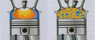
The carburetor prepares a combustible mixture of air and fuel and supplies it to the engine in the required proportions. The design of the simplest carburetor consists of a float and mixing chambers connected to each other. The constant fuel level in the first is regulated by a float. The fuel is transferred to the mixing chamber through a nozzle. When passing through the sprayer, it is broken up by a stream of air and sprayed, mixing with it. The result is a highly flammable air-fuel mixture.
The float carburetor design includes:
- float and its shut-off needle (located in the float chamber);
- jet;
- atomizer and Venturi tube (located in the mixing chamber);
- throttle valve.
Fuel flows from the tank into the float chamber through the fuel line. When the chamber is filled, the float rises to the top and covers the feed with a needle. The nozzle is located at the bottom of the chamber and meters the transfer of fuel for mixing.
The mixing chamber contains a diffuser that thins the air in the area of the sprayer. Thanks to this, the liquid is sucked into the chamber and sprayed.
Types of carburetors
The process of improving the carburetor entailed the creation of a huge number of types of this device by various manufacturers.
Based on the opening time of the mixing chamber dampers, the carburetor is divided:
- with alternate opening of the valve flaps of the secondary chambers;
- with synchronous opening of valve flaps.
Today, types of carburetors can be divided into three main groups:
- Float carburetors are the most optimal and common type of carburetors. Compared to others, it stands out due to its special reliability and simple setup. It consists of a float and mixing chambers.
- Membrane-needle - contains several chambers separated by partitions. The latter contains a piston with a needle, which closes and opens the fuel channel, thereby affecting the valve. The main advantage of this type is simplicity.
- Bubbler - this type of carburetor involves an externally heated steel cylinder. The coke fuel enters a vessel called a bubbler (located at the bottom of the unit) and flows through a layer of heated material. Due to the contact of coke oven gas with the raw material, auto-evaporation of hydrocarbons occurs, after which the gas is saturated with their vapors. Some of the raw materials that have not undergone evaporation are removed from the mechanism from time to time.
Based on the number of mixing chambers, they are divided into: single-chamber, two-chamber and four-chamber.
Why do you need a choke on a carburetor?
The design of the carburetor power system is complemented by a throttle valve, which regulates the air supply to the mixing chamber. The amount of air-fuel mixture supplied to the engine cylinders directly depends on its position. Therefore, it structurally has a direct connection with the gas pedal - when pressed, more air and fuel are supplied for active combustion and power generation.
Some carburetor cars were equipped with a throttle control lever located on the driver's dashboard, which made it easier to start the car when cold. In the Russian-speaking community they called him a sucker. In general, the word reflects the functional role of the lever quite well. When the choke is pulled, the throttle valve is closed and the flow of air into the mixing chamber is limited. Accordingly, the environment in it becomes more rarefied, and gasoline is drawn in in a larger volume. The result is a rich mixture with a higher fuel content, which is excellent for starting the engine.
After starting and warming up the engine to a sufficient temperature, the choke returns to its normal position and the damper is again controlled in the same way.
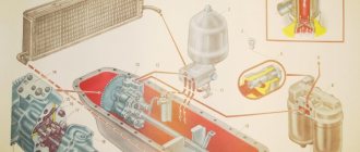
Carburetor design
The undoubted advantage of the carburetor is its simplicity of design; it consists of two elements: a float chamber 10 and a mixing chamber 8.
Fuel under pressure is supplied through tube 1 to the float chamber 10, where the float 3 and shut-off needle 2 are located. This needle is actually a simple valve that regulates the fuel level in the chamber. The presence of such a valve makes it possible to ensure a constant level of fuel in the float chamber during engine operation, and, consequently, the supply of gasoline to the cylinders is carried out evenly. And thanks to the balancing hole (4), atmospheric pressure is maintained in the float chamber.
This is interesting: The smell of gasoline in the car interior
Then the fuel enters through the nozzle 9 into the nozzle 7. In this case, the amount of fuel that comes out of the nozzle depends on the degree of vacuum formed in the diffuser and the diameter of the passing hole in the nozzle.
During intake, the pressure in the cylinders decreases. Air from the environment enters the cylinder through the mixing chamber 8, where the diffuser 6 (Venturi tube) is located, and the inlet pipeline, which distributes the finished mixture among the cylinders.
The atomizer is located in the narrowest part of the diffuser, where, according to Bernoulli's law, the flow velocity reaches the max value and the pressure drops to the min value. The fuel exits the atomizer due to the pressure difference.
Control of the carburetor and throttle valve 5 can be performed exclusively mechanically through communication with the gas pedal, and various automatic systems that were installed on later modifications in carburetor engines. The most widely used carburetor control system is a metal cable, which is characterized by its simplicity of design and reliability.
Air is supplied by opening and closing the air damper. Such a damper on most engines has a semi-automatic stroke. During operation, the operation of the air damper used may be disrupted, which leads to an over-enrichment of the mixture or its depletion. That is why, during the operation of such a carburetor engine, it is necessary to regularly inspect and appropriately adjust the air damper and the entire carburetor.
One of the varieties of carburetors are emulsion versions, in which the atomizer no longer receives liquid fuel, but an emulsion obtained from air and fuel. It is believed that emulsion carburetors provide maximum efficiency, which is achieved due to improved atomization of gasoline in the air mixture.
Typical carburetor malfunctions and their causes
- Difficulty starting the engine when cold: The throttle valve does not close completely when the choke is pulled all the way. The damper drive needs to be adjusted.
- Throttle starting gaps are not adjusted correctly.
- The damper clearances are incorrectly adjusted.
- The cause of the malfunction most likely lies in the high level of fuel in the float chamber. The float mechanism needs to be adjusted or the valve needle needs to be replaced.
- The idle system is incorrectly adjusted.
- The mixture is poorly enriched due to the fact that the accelerator pump nozzle is not tightly secured.
- The mixture is too lean due to a small amount of fuel in the float chamber, clogged nozzles and fuel channels.
Acceleration pump
The accelerator pump is designed to briefly enrich the combustible mixture when the throttle valve is opened sharply.
Rice. Diagram of an economizer with a pneumatic drive: 1 - sprayer; 2 - spring; 3 - piston; 4 - cylinder; 5 - rod; 6 - main jet; 7 — economizer valve; 8 - channel; 9 — valve spring; 10 — economizer jet
In the carburetor body there is a cylinder 8 in which the piston 7 of the pump is placed. The cylinder is connected to the float chamber by a channel, at the beginning of which there is a check valve 9. The outlet channel has a needle valve 10.
The piston is driven by the throttle valve drive mechanism through lever 13, driver 12, rod 11 and pressure plate 4, which acts on the piston through spring 5. When the throttle valve is smoothly opened, the pump piston slowly lowers and gradually squeezes gasoline from the cylinder into the float chamber through the open check valve 9.
When the throttle valve is opened sharply, the piston quickly lowers and squeezes gasoline out of the cylinder. In this case, gasoline lifts the check valve, which closes the inlet, preventing gasoline from escaping back into the float chamber. Gasoline, lifting the needle valve 10, is injected through the nozzle 3 into the carburetor mixing chamber and enriches the combustible mixture.
Pros and cons of a carburetor
Compared to injection systems, the carburetor has a technically simpler design, and this determines its main advantage - low repair cost. Many experienced drivers repair the device themselves without any problems, using kits and parts that are still commercially available. Moreover, repairs do not require special tools or skills. With good instructions, even a beginner can quickly figure it out.
Mechanical carburetors remain operational when in contact with dirt and water (in moderation, of course). Their penetration does not lead to failure or stopping. However, this also comes with a drawback - the device has to be cleaned and adjusted regularly. However, increased resistance to harsh operating conditions compared to electronic carburetors or injectors is a fact.
Another valuable advantage of the carburetor is its unpretentiousness to fuel quality.
In addition to the need for adjustment and cleaning, the carburetor has the disadvantage of potential operational difficulties in certain weather conditions. In particular, at sub-zero temperatures, condensation freezes on its body. In extreme heat, the device overheats and engine power drops due to fuel evaporation. The displacement of carburetors at the end of the 20th century was due to the fact that they do not carry out distributed injection, like injection systems.
Carburetor K-22D
Carburetor K-22D , installed on the engine of the GAZ-69 car, is a three-diffuser carburetor.
The main dosing system of the carburetor operates on the principle of regulating the vacuum in the diffuser. It consists of a main jet 27, the nozzle of which goes into the small diffuser 10, an additional nozzle 25, the nozzle of which goes into the neck of the large diffuser 14, and an automatic bypass air valve, consisting of four elastic plates 5.
The amount of gasoline passing through the main jet can be adjusted depending on the operating conditions of the engine using needle valve 26.
Rice. Carburetor K-22D: 1 - flange; 2 — screw for adjusting the idle mixture quality; 3 - hole for the emulsion to escape during the transition from idle speed to medium speed of the engine crankshaft; 4 - hole for vacuum regulator; 5 - elastic plate; 6 — idle jet; 7 — middle diffuser; 8 — emulsion idle jet; 9 — idle air jets; 10 — small diffuser; 11 — air damper safety valve; 12 — air damper; 13 - tube; 14 - large diffuser; 15 — accelerator pump nozzle; 16 — sprayers; 17 — discharge valve of the accelerator pump; 18— accelerator pump piston; 19 — check valve; 20 - float; 21 - locking needle; 22 — float chamber body; 23 — accelerator pump piston drive rod; 24 — economizer valve; 25 — additional jet; 26 — needle valve of the main jet; 27 - main jet; 28 — economizer jet; 29 - throttle valve
The idle system consists of an idle jet 6, two air jets 9 and an emulsion jet 5.
The economizer and accelerator pump are combined into one system, consisting of an accelerator pump with a piston 18, a pump discharge valve 17, a jet 15, a check valve 19, a jet 28 and an economizer valve 24. The accelerator pump is driven mechanically by the throttle valve.
The float chamber communicates through tube 18 with the air pipe, and not with the atmosphere, as a result of which the influence of the air filter resistance on the operation of the carburetor is eliminated.
When the engine is running at low idle speed, the throttle valve is closed. Due to the high speed of air movement through the narrow gap between the damper and the walls of the mixing chamber, a vacuum is formed in the throttle valve area.
Since the outlet of the idle system is located in this area, the vacuum is transferred to the system and it operates as an independent carburetor.
Gasoline from the float chamber enters the idle jet 6 through an additional jet 25 through the carburetor channels. Having passed the idle jet, the gasoline rises and, meeting the air entering through the air jet 9, mixes with it and passes through the emulsion jet 8 in the form of an emulsion.
Coming out of the emulsion nozzle, gasoline again meets the air flow passing through the air nozzle and is mixed with it. The emulsion exits through the idle hole behind the throttle valve.
The emulsion consumption and, consequently, the quality of the combustible mixture at idle is adjusted by screw 2.
When the engine is running and at medium loads (the throttle valve is open approximately halfway), the vacuum in the diffusers increases so much that the bulk of gasoline comes out of the nozzles of the main 27 and additional 25 nozzles.
As the air flow passing through the diffuser increases, the plates 5 of the air bypass valve diverge and the air flow passes by the small 10 and medium 7 diffusers, automatically adjusting the vacuum in the small diffuser and, consequently, the composition of the combustible mixture depending on the throttle opening value.
When the engine is running at full load, the throttle valve is fully open. In this case, the piston 18 of the accelerator pump is in the lower position and, pressing the economizer valve 24, opens access to an additional amount of gasoline, which from the float chamber passes through the economizer nozzle 28 to the additional nozzle atomizer.
When the throttle valve is opened sharply, the accelerator pump piston drops sharply and squeezes gasoline out of the cylinder. Check valve 19 closes, and valve 17 of the accelerator pump opens, and gasoline is released in a stream through jet 15 into the neck of large diffuser 14 - the combustible mixture is enriched.
When starting the engine, the combustible mixture is enriched by closing the air damper 12, which has a safety valve 11.
The K-22G carburetor, which is installed on the engines of GAZ-63 and GAZ-51 A cars, is also made according to the design of the K-22D carburetor.
Video on the topic
Related publications
- Injector and carburetor: what is the difference and which is better?
- Which is better front or rear wheel drive?
- What is VTEC and what is it for?
- What is a fuel injection pump in a diesel car engine?
Leave a review
Cancel reply