Setting the fuel level
Adjusting the amount of fuel in the chambers of Solex carburetors is a simple procedure and does not require specialized equipment. Although in the factory this adjustment is performed using a special template, which simplifies and speeds up the work. But at home you can do without this template. To carry out adjustment work yourself you need:
- screwdrivers (phillips, flat);
- ruler (preferably a caliper);
- round rod with a diameter of 2 mm (wire or drill will do).
With such equipment you can quickly complete all work.
Characteristics of the 3X sensor
If problems occur with the sensor, you need to immediately pay attention to the light bulbs and the sensor itself.
Purpose and principle of operation
The main task of this device is to turn on the warning lights, notifying people that the car is moving in reverse. It is clear that if the device is unusable, accidents may occur.
The VAZ 2109 reverse sensor works in this way: when changing gears, the shift fork is pressed against the device. This creates a short circuit in the wire and turns on the light, which informs about the movement of the vehicle in reverse.
Typical faults
The most popular problems are:
- The light bulbs burned out. If this happens, you need to remove it and check it with a multimeter.
- Broken contacts.
- The device will not work if the regulator contact is poor, as well as if the contact insulation is poor. Violation of insulation threatens to cause a short circuit.
- In the event of a breakdown, you need to make sure that the fuse in the mounting block is in good condition. If it is damaged or melted, it is worth replacing immediately.
- If the device itself fails, and the symptoms of the malfunction are such that all the lights will not work or, conversely, will work continuously, you need to replace it with a new one.
Recommended Method
Level control technology includes a number of stages:
- We dismantle the housing of the air filter element. To do this, unscrew the fastening nut of the housing cover, unclip the latches, remove the cover, take out the filter and tighten the 4 nuts that secure the housing to the carburetor.
- Raise the body and disconnect the rubber pipes. We move the body to the side.
- Loosen the clamps securing the fuel pipes going to the carburetor and disconnect them.
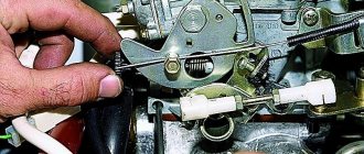
- Remove the wire suitable for the idle speed solenoid valve;
- Disconnect the drive cable of the air damper (the “choke” handle);
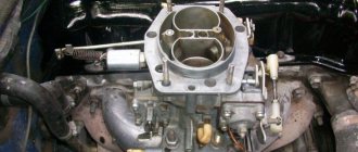
- Unscrew the 5 screws securing the carburetor cover;
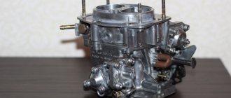
- Having removed the cover, we immediately determine the fuel level in the chambers by lowering a ruler or caliper into one of them until it stops (using its depth gauge). If the measurement shows a level of 25-26 mm, it corresponds to the norm and no adjustment is required;
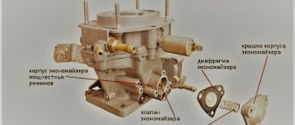
If the amount of fuel in the chamber is lower or higher than normal, we perform a visual inspection and a series of measurements on the floats, and if necessary, we correct their position. To carry out adjustment work, place the removed carburetor cover on a flat horizontal surface with the floats facing up.
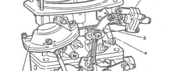
First, we look at the position of the elements from above. The outer side surfaces of the floats are parallel to the special imprints on the gasket. Deviations can cause the floats to touch adjacent elements and surfaces, causing the fuel level to be incorrect. If necessary, adjust the position of the floats by bending their mounting arms. The next step is to measure the gap between the floats and the gasket. A rod with a diameter of 2 mm is useful here - this is how much the specified gap should be.
If it does not correspond, we bend the tongue of the floats, with which they act on the locking needle. After this adjustment, we check the total height of the floats, which is normally 34 mm. If this is not the case, check the gap again, adjust it if necessary and measure the height again.
The last stage of setup is determining the working stroke of the floats. To do this, place a caliper near the float, mark the distance from its lower corner to the surface of the cover, then lift the float with your hand and mark where the lower corner is.
A working stroke of 15 mm is considered normal; if it differs, it is adjusted by bending the tongue.
Removing the device
If you nevertheless determine that the idle speed sensor is broken, then you will need to replace it with a new one. To dismantle this part, no special skills are required. The above-mentioned VAZ 2109 and 21099 sensor is installed on the throttle body body and attached to it with two bolts, for example, like a fuel pump. In order to remove this device, it is enough to unscrew the two mounting bolts and remove the bundle of wires connected to the device. Before performing this work, it is recommended to disconnect the battery by removing both terminals from it.
Before installing a new part, be sure to sand the joint. Also, if necessary, you need to replace the gasket.
Non-standard way
There is a simpler method for determining the correct position of the floats, which does not require measurements. Place the carburetor cover on a flat table and look at the stampings made on the side surfaces. When the floats are in a normally adjusted position, these strips are parallel to the lid.
Then we lift the floats up and look at their bottom, which after lifting should be parallel to the surface of the lid. If necessary, adjust the position of the floats by bending the tongue.
After adjustment work, we assemble the carburetor.
Valve check
There are three main steps to checking the functionality of the solenoid valve.
| Verification method | Your actions |
| Basic operating mode of EPHH |
|
| Engine braking mode |
|
| Fuel cut-off when ignition is turned off |
|
In addition to the solenoid valve itself, you should also definitely check the EPHH control unit.
Plus and minus
Checking the control unit
To check the control unit of the solenoid valve of the carburetor VAZ 2109 you will need a wire. The length of the wire should be such that it is sufficient to connect the valve to the positive terminal of the battery. Plus, you will need a standard voltage control light.
Your steps when checking the control unit will look like this.
- Disconnect the power wire from the valve without interfering with the operation of the carburetor itself. After this, connect the valve via the prepared wire to the positive terminal of the battery.
- The supply wire of the solenoid valve, which you disconnected in the previous step, must be connected to the positive terminal of the control lamp. The minus connects to the mass.
- Turn on the engine and let it idle for a while. The crankshaft should rotate at a speed within 850-900 rpm. The control lamp should light up.
- Begin to gradually increase the speed, reaching 2100 units per minute. If the control unit is working properly, when this level is reached, the light will go out. Reducing the speed again to 1900 units per minute, the lamp should light up.
Useful diagram
If a malfunction was discovered during the check of the valve and its control unit, you will need to replace the corresponding failed components of the carburetor power system of the VAZ 2109.
EPHH is an important component of the car, which requires constant monitoring by the car owner.
Loading …
Idle speed adjustment
The second setting of the VAZ-2109 carburetor is idle speed, it can be partial or full. The first is for minor speed adjustments, the second is for adjusting the amount of air (setting CO emissions in the exhaust gases).
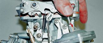
Partial adjustment is performed using the air-fuel mixture “amount” screw. This screw sets the opening angle of the throttle valves, which ensures that the air-fuel mixture enters the cylinders when the accelerator pedal is released. The “quantity” screw rests on the throttle valve control lever and when screwed in, it pushes the lever, causing the valves to open slightly.
Partial idle adjustment is performed with a warm engine and creating a load on the vehicle's on-board network by turning on the high beam headlights and the interior heater at full power. The adjustment is carried out with the engine running by screwing in/unscrewing the “quantity” screw until the optimal idle speed is established, which for the VAZ-2109 is 800-900 rpm (this can be tracked using a standard or plug-in tachometer).
If it is not possible to set the required speed or the motor operates unstably at it, a complete adjustment is made, which is made by two screws - “quantity” and “quality”.
The algorithm for this adjustment consists of the following stages:
- Warm up the engine and then turn it off;
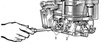
- We find the quality screw (it may be closed with a plug that will have to be removed), screw it in until it stops, and then unscrew it 3-4 full turns;
- We start the engine, turn on electrical consumers (lighting and stove) to create a load in the on-board network;
- By rotating the “quantity” screw, we achieve 700-800 rpm on the tachometer;
- By turning the “quality” screw, we set the maximum possible speed (they will increase to a certain level, and then stop. The moment the speed increase stops is considered the maximum);
- We set the “quantity” screw to 900 rpm;
- Using the “quality” screw we lower them to 800 rpm;
- We slowly tighten the “quality” screw until interruptions appear in the operation of the power plant, after which we unscrew it back 1 turn;
- We adjust the speed with the “quantity” screw, bringing it to a normal value - 800-900 rpm;
After the adjustment operations, we check that they were carried out correctly. This is done by sharply pressing the gas pedal and then quickly releasing it. With a properly configured carburetor, the engine should respond quickly to pressure, without any failures or hesitations. And after releasing the pedal, the speed will drop to the idle level, without sags or instability of the engine.
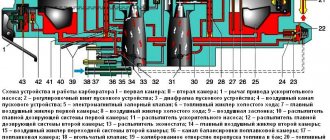
Principle of operation
The idle speed sensor consists of several parts, namely: an electric motor, a valve, a rod, a shut-off needle and a spring. While the car is moving, the valve of the device is stationary. And as soon as the injector goes to idle and the throttle valve closes, the valve begins to work and pump air, bypassing the closed valve.
The electric motor forcibly drives the valve during idle. The rod serves to connect the electric motor to the valve and transmit reciprocating movements to it. The shut-off needle, in turn, blocks the air flow at the moment when the VAZ 2109, 21099 injector receives speed in a engaged gear.