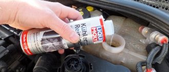
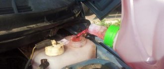
A couple of weeks ago I finally installed an additional coolant temperature sensor Defi BF 60 mm (replica) =) Those who follow my car already know that earlier I had already inserted a 34 mm Defi adapter (replica) into the upper (“hot”) one radiator pipe even when replacing the coolant as part of TO-4. I’ll say right away that you need to throw “mass” from it onto the body, otherwise the sensor will not show you anything! I also ran the wiring from the sensor into the interior. And finally I installed the “alarm clock” itself =) I think everything will be clear from the photo, but I want to say a few words about the connection (after my video). I stupidly took the power from the Espada E 13U cigarette lighter splitter =), I don’t like any dimming of the backlight, I made myself a stupid white backlight - twisting the white wire with the red one to “+” and the black wire to “-“, respectively. All! Ready! =)
I’ll tell you right away why I need an additional coolant temperature sensor - control of the opening of the thermostat, prevention of accidental overheating of the internal combustion engine and simply the aesthetic pleasure of having the “alarm clock” itself on the panel =).
Here is a video of this device working ⇩⇩⇩
There are 3 connectors on the back of the sensor:
Connector No. 1.
Responsible for supplying power to the sensor; a four-pin power plug is connected to it (Fig. 2).
In order for the sensor display to be illuminated in white, you need to connect the white wire to the plus, the yellow wire should be left unconnected. In order for the sensor display to be illuminated in red, you need to connect the yellow wire to the positive. You can also make a combined backlight using white backlight in the daytime, and red backlight in the dark (when the dimensions are on). To do this, you need to connect the white wire to the positive, and connect the yellow wire to the side lights power supply and vice versa.
Connector No. 2.
The manager is responsible for supplying information to the sensor from the sensor. A two-pin plug is connected to it (Fig. 3).
Connector No. 3.
Duplicates connector No. 1. If more than one device is installed on a vehicle, then power for subsequent sensors can be taken from connector No. 3. so as not to pull unnecessary wires.
Position 4 indicates the settings button.
How to actually set up the device:
1. Turn off sound signals.
To turn off the sound signal on the sensor, you need to hold down the control button on the rear panel and turn on the car's ignition. Hold the button while the test mode is running. The button must be released after the sound signal ends. The sound will be muted. To turn on the sound you will need to do a similar operation.
2. Setting peak values.
To set the critical value at which the sound and light alert (PEAK) will be triggered, you need to supply power to the sensor, wait for the test mode to complete, hold down the control button on the rear panel and hold for 5 seconds. The arrow will move to the preset critical level. You can change the values either by short pressing the button (the arrow will move through each division) or by holding the button (the arrow will move through 5 divisions). To decrease the Peak values, you need to bring the arrow to the maximum, then it will go in the opposite direction.
VAZ 2108, 2109, 21099 cars have a dial gauge for the coolant temperature in the instrument panel.
Connection diagram for the coolant temperature indicator sensor in the cooling system of VAZ 2108, 2109, 21099 cars up to 1998. with mounting block 17.3722 and “low” instrument panel
Connection diagram for the coolant temperature indicator sensor in the cooling system of VAZ 2108, 2109, 21099 cars after 1998. with mounting block 2114 and “high” instrument panel
Notes and additions
— The cooling system of carburetor engines of VAZ 2108, 2109, 21099 cars is equipped with another temperature sensor - the cooling system fan switch sensor (TM-108). It is installed in the radiator tank and its signal turns on the radiator fan.
— The cooling system of an injection engine also has a coolant temperature indicator sensor. The control function of turning on the fan is carried out by the control unit (ECU) based on a signal from the coolant temperature sensor (DTOZH), installed in the pipe near the thermostat.
More articles on the engine cooling system of VAZ 2108, 2109, 21099 cars
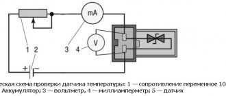
A variety of signaling devices are used to monitor the operation of an internal combustion engine. We suggest considering how the coolant temperature sensor works, how it is checked and replaced if it is faulty.
Crankshaft sensor location
The location of the DPKV is a bracket that is located in the central part of the pulley on the generator drive.
It is installed next to the drive toothed pulley structure with a gap of 1-1.5 mm. To replace the sensor or adjust it, you need to connect a wire 50-70 cm long to it. To set or correct the position, you need to adjust the washer, which is fixed above the DPKV mounting socket.
Before replacing this device, it is recommended to diagnose it. Many car enthusiasts are concerned about the question of what else needs to be done before removing it - measurements should be taken based on the ratio of the mounting bolts to the body and the position of the DPKV.
Types of sensors for measuring the temperature of the cooling system fluid
Outdoor temperature sensor
The following types of sensors are used to measure coolant temperature:
- magnetic sensor;
- bimetallic sensor;
You can independently determine the type of sensor by the reaction speed of the temperature gauge after the ignition is turned on. If a magnetic sensor is installed in the car, then the temperature gauge needle reacts instantly after turning the key in the ignition switch. In the case of a bimetallic sensor, a slow rise of the arrow is noted.
The magnetic temperature sensor consists of two coils that are located on the sides of a rotating metal armature. The said anchor holds the temperature gauge needle. The coils are powered into the vehicle's electrical circuit, one wire is grounded, and the second goes to a sensor that produces different resistance depending on the temperature of the internal combustion engine. The passage of electricity through the coils results in the formation of a magnetic field, which moves the armature with an arrow attached to it. The difference in the magnetic field that the coils create depends on the current supplied to them by the temperature sensor, and also determines the degree of displacement of the armature with the arrow.
The bimetallic sensor is based on the tendency of metal to expand when heated and contract as a result of cooling. The use of metals with different expansion coefficients in the sensor design allows the temperature to be accurately recorded.
The operating principle of a bimetallic temperature sensor can be seen in the following example. Two plates, one of which is made of steel and the other of copper, are tightly connected to each other. Next, they are heated, resulting in expansion. Copper has a greater coefficient of expansion compared to steel, which will cause the copper plate to increase in length relative to steel. Since the two plates are securely connected to each other to prevent movement, the copper plate will begin to bend around the steel plate.
As for the bimetallic temperature sensor in the engine, the design includes a special rod, which, as a result of heating, exhibits a change in its length. The result is an increase or decrease in the current that is supplied to the arrow block on the instrument panel.
The warning light on the instrument panel (if equipped) is based on the same principle. With a certain heating, the plate bends, which leads to the contacts connecting and the engine overheating lamp to light up.
Among the blocks that interact with temperature sensors, there are two types:
- semiconductor block;
- bimetallic strip block;
The semiconductor-type sensor block is most widely used today, based on a semiconductor resistor in a metal housing. A semiconductor is characterized by its ability to reduce resistance as temperature increases. As the internal combustion engine heats up, the resistance decreases and the current in the sensor increases.
The bimetallic block works on the principle of displacement of a bimetallic strip, which is located inside the heating coil. As a result, there is an increase or decrease in the current that is supplied to the instrument panel.
Characteristics and features of replacing regulators
Where is the oil pressure sensor on Kamaz?
On products of the domestic automotive industry such as UAZ and Niva, various sensors are needed to transmit information to the dashboard. Also, some of them perform additional functions. And each has its own characteristics of dismantling and installation.
Detonation
The phenomenon of detonation is the explosive combustion of fuel in an engine due to glow ignition. SUVs like the Niva suffer from this problem quite often.
A piezoceramic element is installed in the area of the cylinder block - this is the knock sensor. Its function is to transmit a signal to the controller, which will automatically adjust the ignition timing. Thanks to this, the phenomenon will be eliminated. Also, thanks to the sensor, the controller provides a light indication of an emergency situation on the instrument panel.
The Niva knock sensor can be removed using only a screwdriver and a 13mm wrench. Remove the block by pressing the lock, then unscrew the bolt with a wrench.
Camshaft
This part is required to determine the angular position of the timing mechanism in accordance with the crankshaft. Information from it enters the engine control system. It is used to regulate fuel injection and ignition.
Experts recommend changing this part every 100 thousand km or 5 years. This is due to the fact that it is subject to constant temperature changes, which negatively affects the operation of the sensor. Unfortunately, it is quite difficult to independently determine its malfunction; this requires an oscilloscope and other equipment.
Speeds
The Niva 21214 has an electronic, also known as cableless, speed sensor. Its main function is to transmit information about the vehicle speed to the speedometer. You will find this parameter finder on the gearbox, on the rear transfer case cover.
To replace it, you will need to get to the car from below, using a hole or other method.
- Squeeze out the plastic clip and remove the terminal with wires.
- Then use a wrench to unscrew the device. If it doesn't come off, there's no need to pull. The problem is corrosion; WD-40 solvent will help to cope with it; you need to apply it to the connection and wait.
- Install the new part in the reverse order.
Idle move
The idle speed sensor, also known as the regulator (IAC), is located on the throttle valve.
- A block with wires is connected to it, which is removed by releasing the latch. Then you need to unscrew the two bolts using a Phillips screwdriver.
- Then you can simply pull out the sensor.
- When installing, perform the same steps in reverse order.
Fuel level
This sensor is required to display information about how much gas you have left. In some cases, it becomes unusable and needs to be replaced.
First, you'll need to remove the floor mats and rear seat to gain access to the hatch where the gas tank is hidden. The hatch is a sheet secured with 12 screws. Unscrew them and remove the hatch completely by lifting it up and sliding it forward.
Now you can see the gas tank and fuel pump. Remove the connector from the latter by placing a rag under the draining gasoline. It is better to dismantle by draining 5-7 liters from the tank if it is full.
The sensor is installed in a recess at the top of the gas tank. Disconnect the wire block by pressing the plug, and then remove the sensor itself. Install in reverse order.
This sensor is used to determine the coolant temperature. Also, it is its readings that are used automatically to turn on the fan. Thus, the DTOZH and the fan switching sensor are one and the same thing on Niva cars. But on other machines these may be two different parts.
You will find it on the cylinder block. To remove, first drain the coolant. Then, disconnect the wire. The sensor itself is unscrewed with a spanner set to “21”. When installing a new regulator, lubricate its threads with sealant and perform all steps in reverse order.
How to connect the coolant temperature sensor?
The sensor is installed very easily: it is screwed into the mounting socket, after which the thread is tightened and the wiring is connected, the air filter is put in place and the main air flow sensor power supply block is connected.
It is strictly forbidden to use sealant in this case. When the engine is running, the cooling system and metal elements become very hot, and the sealant may melt.
If this happens, the sealant will get into the antifreeze and the cooling system may fail.
Coolant temperature sensor connection diagram:
Replacing DTOZH, video:
The principle of operation of the EGR valve and what it is
Where is the fan switch on VAZ 2114 photo?
Engineers and designers of leading automobile companies work every day to improve the vehicle exhaust system. During operation of the internal combustion engine, exhaust gases are released into the environment, and it has long been a known fact that these gases contain a large number of chemical compounds hazardous to health. Nitrogen oxide and dioxide are considered the most harmful. Deviation of the concentration of these substances in the air from the norm provokes the occurrence of a number of diseases of the human cardiac and respiratory system.
The most rational way to reduce the toxicity of exhaust gases today is the use of the EGR system, the principle of which is exhaust gas recirculation. Ignition of a flammable mixture is possible only at high temperatures and appropriate pressure. But the catch is that these are the conditions that are ideal for the formation of oxide by combining oxygen with nitrogen.
The EGR valve allows some of the exhaust gases to be sent to a portion of fresh air. The consequence of this is a decrease in the amount of oxygen in the mixture. A lean mixture needs a completely different temperature. It no longer requires 1400 or more degrees Celsius to ignite.
Many drivers believe that the EGR valve reduces engine power, which has a detrimental effect on the technical performance of the car. It is for this reason that the system has not yet found proper distribution in the post-Soviet space. However, experiments and studies show the opposite: EGR does not reduce engine power, but increases it. This may be by reducing the number of detonations in the gasoline power unit.
Summing up the intermediate results, it can be noted that the USR valve allows:
- Improve the quality of fuel combustion;
- Reduce engine detonation;
- Reduce the amount of emissions of harmful substances;
- Provide auxiliary control of exhaust gas toxicity.
It remains to be found out on what principle the valve works? Today, modern cars are equipped with an ECU, which is a real “brain center”. Based on the data received from various sensors (TNA sensor, EGR level sensor), the control unit determines the optimal time for supplying exhaust gases to the intake manifold. Gas supply is possible due to a signal from the computer, which forces the solenoid valve to open and conditions are created for a vacuum in the pneumatic valve.
Diagnosis of CPPV and DPRV
There can be many reasons for interruptions in the operation of the internal combustion engine. However, despite the somewhat inconvenient location, diagnosing the crankshaft sensor is the least labor-intensive process. Then, based on the results, you can look for the breakdown further or replace the crankshaft sensor if the check reveals a fault. The diagnostic principle is from simple to complex, that is, visual inspection, then checking with an ohmmeter, then with an oscilloscope or on a computer.
Visual inspection
Since the sensor is installed with a gap adjustment, you must first check this distance with a caliper. The next steps to check the crankshaft sensor visually are:
- identification of foreign objects between it and the flywheel;
- presence of dirt in the area of missing teeth of the synchronization disk;
- wear or breakage of teeth (very rare).
Inspection of the DPKV
In principle, at this stage the car owner does not encounter any difficulties. Further checking should be done with instruments, preferably a multimeter (tester), which can be switched to ohmmeter, voltmeter and ammeter mode.
Ohmmeter
At this stage, checking the crankshaft position sensor does not require special knowledge and experience:
- the multimeter is set to the ohmmeter position (2000 Ohm);
- the resistance on the sensor coil is measured with a tester;
- its value fluctuates in the range of 500 – 800 Ohms;
- any other value automatically indicates that the DPKV repair is necessary.
Checking with an ohmmeter
Deep check
Before replacing the crankshaft sensor, a comprehensive inspection is recommended. The main conditions for its implementation are:
- room temperature (20 degrees);
- the presence of a transformer, meter, voltmeter, inductance meter and megger.
The check sequence is as follows:
- 500 V is supplied to the winding by the transformer;
- insulation resistance must be within 20 MΩ;
- The coil inductance is 200 - 400 mH.
In-depth check of DPKV
If the specified parameters are within normal limits, and the Check error is displayed on the panel, then the cause of the malfunction lies in other components of the internal combustion engine. The signal is transmitted from the sensor without distortion. If any characteristic deviates from the nominal value, the crankshaft position sensor must be replaced.
Oscilloscope at a service station
In addition to the unaffordable price for the average car enthusiast, the oscilloscope requires highly qualified users. Therefore, if there is a question of professional diagnosis of CPCV, it is better to go to a specialized car service center.
The check is carried out locally, the wire is not disconnected from the computer:
- the device is set to InductiveCrankshaft mode;
- The oscilloscope clamp is connected to ground;
- one connector is connected to USBAutoscopeII, the second to the A-terminal of the sensor;
- The engine is cranked by the starter or started as soon as possible.
Checking with an oscilloscope
Any deviation in the amplitude of the waves on the oscilloscope screen will indicate that the wire is transmitting a distorted signal from the sensor.
How to check the coolant temperature sensor?
In order to check the device, it must first be removed.
Dismantling is very simple:
- As a rule, the sensor is located on the cylinder head pipe and in order to remove it, you first need to remove the air filter;
- then the negative cable is removed from the battery;
- coolant is drained from the radiator;
- the wiring is disconnected from the device;
- using a suitable wrench (most often 19–21), the tightening is loosened, after which the sensor can be easily dismantled.
After the sensor has been removed, it is placed in a container with coolant and it is gradually heated. The process is accompanied by constant monitoring of the temperature and the readings of an ohmmeter, which is connected to the sensor.
There is a special table corresponding to the coolant temperature and ohmmeter readings.
| Temperature, °C | Resistance, Ohm | Voltage, V |
| 4800 — 6600 | 4,00 — 4,50 | |
| 10 | 4000 | 3,75-4,00 |
| 20 | 2200 — 2800 | 3,00 — 3,50 |
| 30 | 1300 | 3,25 |
| 40 | 1000-1200 | 2,50 — 3,00 |
| 50 | 1000 | 2,50 |
| 60 | 800 | 2,00-2,50 |
| 80 | 270 — 380 | 1,00-1,30 |
| 110 | 0,50 | |
| open circuit | 5,0 + 0,1 | |
| short circuit to ground |
When the readings from your device do not agree with the data from the table, the sensor must be replaced, since it can no longer be repaired.
If it turns out that the sensor is in working order, the fault needs to be looked for further. There may be some problem with the thermostat.
You can see an example of how to check the coolant temperature sensor by watching this video:
Detecting a sensor malfunction and replacing it
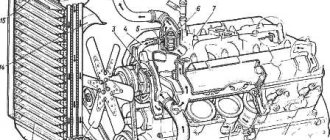
Design of the cooling system of Lada Kalina 1 - expansion tank; 2 — radiator outlet hose; 3 - inlet hose; 4 - radiator; 5 — steam exhaust hose; b — radiator supply hose; 7 — electric fan; 8 — electric fan casing; 9 — coolant temperature sensor; 10 — coolant temperature indicator sensor; 11 — throttle assembly; 12 — bracket for the coolant pump pipe; 13 — coolant pump; 14 — coolant pump pipe; 15 — heater radiator supply hose; 16 — heater radiator outlet hose; 17 — exhaust pipe; 18 — coolant pump pipe hose; 19 — thermostat housing
To determine that the evaporator temperature sensor is faulty, you should first conduct a visual inspection, thorough and consistent
Particular attention should be paid to wires and their connections, since this is where microscopic breaks most often occur. In addition, rust deposits, even in minute doses, can lead to failure.
Cracks in the housing cause coolant to leak, which is also bad. So, if Kalina’s control unit receives dubious information about the coolant level, if the engine begins to give unjustified failures and then completely stalls, if the engine suddenly begins to lose power and controllability while driving, in 80 percent of cases this may indicate sensor malfunction.
Therefore, in order to determine the location of the breakdown, you should first check this device. In addition to these symptoms, the following signs indicate that the coolant temperature sensor needs repair:
- at idle speed the engine is unstable, starting is difficult, stalling occurs;
- fuel consumption suddenly increases;
- The control lamp warns of overheating.
You can determine whether the interior temperature sensor is working by checking the resistance and voltage. To diagnose, you need to remove the sensor, then lower it into a container of water, the temperature of which is alternately changed. In warm water, the voltage should vary from 3 to 1 W for 4-5 minutes. In addition to monitoring the sensor, other systems should be carefully checked.
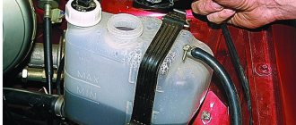
Radiator and coolant level
It is very important to know here that the radiator cap can only be removed when the engine has cooled down, otherwise it is easy to get a serious burn. The tightness of the lid should also be checked. If the cover is not airtight, then air enters the system, which leads to overheating of the motor and, as a result, distorted sensor data
And lastly, it is necessary to monitor the performance of the fan, on which a lot also depends. To dismantle the Kalina DTOZh device, you must first disconnect the negative wire from the battery. Next, you need to drain all the coolant. The third step is to disconnect the wiring from the sensor. Now we arm ourselves with a 21 key and unscrew the device.
Install the new one in the reverse order. Don't forget to fill the radiator with antifreeze at the end of the job. The temperature sensor is changed only as a last resort, when it is known for sure that it is faulty. Checking the device was discussed in the previous paragraph. But sometimes the sensor changes even in its functional state. When is this done? If it is necessary to completely overhaul the Kalina engine or replace it.
Such changes primarily affect the operation of the sensor, so in order to avoid possible difficulties and troubles, it is better to replace the device with a new one. In the event of emergency overheating of the power unit and the sensor, problems occur
Therefore, when doing repairs, do not forget to pay attention to the sensor
Signs of a malfunctioning coolant temperature sensor
Since the DTOZH is responsible for many functions in the car, its malfunction will lead to various problems in the operation of the entire system. Here are some signs of a malfunctioning coolant temperature sensor:
- instability of engine operation - troits, stalls;
- idle speed range from 200 to 1500 per minute, sudden jumps;
- difficulty starting the engine;
- sudden turning on of the cooling fan in cold weather;
- unreasonable increase in fuel consumption;
- dark, black smoke from the exhaust pipe.
These alarming symptoms may also indicate other problems in the car, but the first thing you should pay attention to is the sensor.
Replacing the sensor
To begin repairing the coolant sensor, you need to determine its location. Most often it is installed near the thermostat or radiator; in some cases, the on-board computer uses readings from both sensors or one of them, depending on the make and model of the car. For example, this is how the sensor is located in Renault, Chevrolet, Citroen, Skoda, Chery, KIA, Subaru Impreza.
There are several ways to help you find out that the sensor needs to be replaced. If all other systems in your car are working, then the dashboard will indicate a malfunction using a light signal. If the car has computer control, then the problem can be determined by deciphering the combination on the monitor.
Photo - temperature sensor on the dashboard
Depending on the year of manufacture of the car, as well as its brand, many car enthusiasts note an increase in engine fuel costs. But at the same time, you need to understand that diesel cannot be defined this way (UAZ, PAZ and others). If you have a mechanic and not a computer control system, then here are the signals that you need to buy a new coolant temperature sensor:
- The car began to consume more fuel than usual;
- When the car starts and the engine reaches its maximum temperature, it stalls;
- There were problems starting up;
- Black smoke comes out of the muffler pipe.
Let's look at how to replace the G62 coolant temperature sensor on a Kia Sportage with a 2-liter engine. Similar instructions will also be useful when repairing Acura, BMW, Buick, Chevrolet, Ford, Toyota, Volkswagen, VAZ 2110/2112 injector, Renault Grand Scenic and others.
Photo - different coolant temperature sensors
In this model, if the coolant sensor breaks down, alarm 117 is received, which indicates that further operation of the device is impossible and it is necessary to install a new alarm. In Chevrolet the number PO118 is a high signal. The general scheme of work looks like this:
- To get to the sensor, you need to remove the air duct that cools the air filter housing and is connected to the radiator using two bolt connections and an air supply hose. Unscrew the bolts and remove the clamp, carefully remove the entire system. Disconnect the electrical wires from the sensor to correctly measure the resistance. Set the multimeter to ohmmeter mode and set the value to 1000 ohms. Connect the device pins to the positive and negative terminals. Normal resistance should be within 2700 Ohms when the motor is off. To check the sensor with the engine running, you need to move the tester away from the rotating parts of the car;
- Once you are sure that the temperature sensor needs repair, you need to disconnect it from the engine. To continue removal, you must first drain the antifreeze fluid from the radiator using the drain valve. Afterwards, check the radiator and sensor contacts again and unscrew the adjusting bolt as in the photo;
- Assembly is done in reverse form. It must be remembered that practically the main characteristic of the coolant temperature sensor is the material of the washer. If the washer is copper, then the thread of the alarm does not need to be treated with sealant; otherwise, be sure to lubricate the device.
Advice from car enthusiasts on the forums: if for some reason you cannot immediately understand the coolant temperature sensor after a breakdown, then you can connect an additional one instead (such a connection may differ slightly in temperature from the main one).
Checking the coolant temperature sensor
If the inspection does not produce results, it is necessary to measure the resistance and voltage of the sensor at different temperatures
. After starting a cold engine, as it warms up, the resistance should drop (or increase in the case of a positive temperature coefficient of the sensor) in accordance with normal values.
You can check the coolant temperature sensor yourself
Normal resistance and voltage readings for a NTC coolant temperature sensor
| Coolant temperature (°C) | Resistance (Ohm) | Voltage (V) |
| 4800 – 6600 | 4,00 – 4,50 | |
| 10 | 4000 | 3,75-4,00 |
| 20 | 2200 – 2800 | 3,00 – 3,50 |
| 30 | 1300 | 3,25 |
| 40 | 1000-1200 | 2,50 – 3,00 |
| 50 | 1000 | 2,5 |
| 60 | 800 | 2,00-2,50 |
| 80 | 270 – 380 | 1,00-1,30 |
| 110 | 0,5 | |
| open circuit | 5,0 ±0,1 | |
| short circuit to ground |
Normal resistance and voltage indicators for DTOZh with a positive temperature coefficient
AutoOt.ru » Car repair » Where is the coolant temperature sensor located?
Purpose of the DPKV sensor
In the electronic ignition systems of modern cars, the injection of the fuel mixture into the cylinders and the supply of a spark from the spark plug after its compression is carried out by the on-board computer. The DPKV sensor is used to determine the spatial position of the pistons at each moment of time. It is this electronic device that transmits a signal to the computer to carry out the specified sequence of actions by electronic ignition of the car.
Purpose of the crankshaft sensor in the on-board network
Regardless of what modification the crankshaft sensor is used, signs of malfunction of this device are expressed in the absence of a spark/fuel injection or disruption of this cycle. In other words, the internal combustion engine either cannot be started, or the engine stalls spontaneously after a while. This indicates that the piston position signal at bottom and top dead center is distorted.
Less often, the wire connecting the DPKV to the ECU gets damaged; in this case, the signal does not enter the on-board computer, and engine operation is impossible in principle.
On which internal combustion engines is it installed?
Such a device cannot be mounted on cars without an on-board computer and on carburetor engines. Therefore, DPKV is present only on diesel engines and injection engines. To find out the location of the crankshaft sensor, you need to take into account the features of its operation:
- parts of the crank group, pulleys and flywheel are attached to the crankshaft;
- The crankshaft is hidden in a tray; belts of gears of the same name are put on the pulleys, so it is very difficult to attach the sensor near these parts;
- The flywheel is the largest part and relates to several engine systems at once, so the DPKV is connected near it to ensure quick access during replacement.
DPKV is installed only in internal combustion engines with electronic ignition
DPRV sensor
In addition to the crankshaft sensor, the internal combustion engine can be equipped with a DPRV sensor, which is responsible for supplying the fuel mixture and spark to a specific engine cylinder. It is not the main electrical device; unlike the crankshaft, it is mounted on the camshaft. Its second name is pulse-type phase sensor.
DPRV sensor
If the DPRV is faulty, the motor will not stop working, but the injectors will fire twice as often in pair-parallel mode until the problem is resolved.
DTNV Installation Guide
How to install or replace an outdoor temperature sensor at home?
If your machine is not equipped with this regulator, the installation procedure is as follows:
- First you need to purchase an ambient temperature sensor and select a location for its installation. It must be taken into account that the controller should not be exposed to high temperatures from the power unit. The most suitable location for installation is next to the radiator unit.
- The device needs to be fixed, after which the cable with ground needs to be routed into the car interior.
- The dashboard is being dismantled. Depending on the vehicle model, you need to find a contact for connecting the regulator; at this stage you should use the service manual.
- If errors occur in the operation of the controller, you need to disconnect the battery for some time (usually 10-15 minutes is enough), then turn it on again and check the functionality of the device.
Operating principles and design of the speed sensor
The operating principles of all vehicles have seriously improved over time. Thus, mechanical speed detectors, based on the analysis of the rotation of special cables, have sunk into oblivion, and they have been replaced by digital speed sensors. How does a typical representative of such devices work? It’s extremely simple, using the Hall effect, that is, by analyzing electrical impulses coming from a rotating wheel. To be more precise, a typical car speed sensor (abbreviated as DSA) is a small element of the speedometer drive and is usually located in the area of the engine gearbox.
Today it is customary to distinguish three types of sensors:
- reed;
- inductive;
- based on the Hall effect (modern electronic speed sensors).
“Hall” identifiers are the most used in the modern automotive industry and are used in the design of most cars. A similar sensor for measuring the speed of a car operates on the basis of the Hall phenomenon, which involves determining certain physical indicators (in our case, the speed of movement) by analyzing the frequency of electromagnetic pulses. Considering the principle of operation of the device in more detail, it is worth highlighting the following main stages of its operation:
- The pulse speed sensor is mounted in the speedometer drive, which monitors the rotation speed of one of the wheels, and together with it forms a single electrical circuit;
- The speed detector is made in such a way that during its operation, it transmits 6004 electronic pulses to a special controller per 1 kilometer of vehicle movement. The frequency of pulse transmission increases proportionally with increasing machine speed;
- Analyzing this change, the previously noted controller with an electronic “brain” calculates the exact speed of the car at a given time and transmits the obtained indicators to the control units of some vehicle components (injector, carburetor, gas pump, etc.), as well as to the driver through the speedometer . Note that the sensor has virtually no resistance, so its physical design does not affect the resulting speed one bit.
Cleaning and main signs of system failure
At the first stage of cleaning, the recirculation channels are placed in a special cleaning solution. Many experienced drivers use carburetor flushing agent as a solution. At the second stage, the channels are blown out using special devices. It is recommended to do this work only with the valve open.
If it was not possible to clean the device, then the only correct solution would be to purchase a new copy. Carbon deposits are not the only reason for the failure of the USR. A number of other malfunctions associated with the vacuum booster and thermal valves occur in the recirculation system. The valve itself is considered the most vulnerable point in the system. In addition to clogging and soot, it is constantly exposed to high temperature. For this reason, it may periodically jam in the open or closed position.
The valve breaks down, the system stops performing its duties, the amount of nitrogen oxide in the exhaust gases exceeds all permissible levels. But this is not the only problem that arises due to EGR failure. The following symptoms are usually classified as malfunctions:
- At idle, unstable engine operation is noted;
- Decrease in diesel power;
- Manifestation of vehicle jerking at high speeds;
- Rapid wear of spark plugs and clogging of injectors.
Is there an effective way to determine the cause of a breakdown and which specific system component has failed? A quick and effective diagnostic method is scanning the system using electronic equipment. This pleasure is not cheap, but even if it is possible to undergo diagnostics, the result will not always be positive. The reason is that there is not a sufficient information base on errors and there is no way to compare the actual and nominal characteristics of the element.
Some of the most common mistakes:
- USR system error - code P0400;
- EGR valve error - code P1403;
- Gas recirculation circuit error - code P0403;
- Error in valve operating elements - code P0404.
Drivers also often wonder: where is the EGR valve located? It is impossible to give a definite answer to this question, since the location of this element in different brands of cars varies significantly. But, as a rule, the valve is always located near the main power unit of the machine. For example, on the Opel Astra the USR valve is located under the engine protective cover in the right corner, and on the Opel Omega on the right side of the ignition distributor. In any case, if you cannot find this element of the engine compartment, you should always first focus on the tube that is connected to the valve.
Where to look for a breakdown?
Which sensor is responsible for engine speed?
The answer to this question is both simple and complex at the same time. The reason may be in 4 different sensors:
- (DHH);
- (DPDZ);
- (DFID);
- Exhaust gas recirculation ().
Also, in very rare cases, the cause of floating speed may be the crankshaft position sensor. But this happens extremely rarely and we will not consider this option here. Typically, problematic sensors are identified during computer diagnostics. But sometimes it is not possible to visit the service for this procedure. Therefore, you can completely do it yourself to check them.
Finally, make sure you are testing the correct sensor. Hot fuel has the same effect as higher cetane fuel at a lower temperature in that it burns more easily. Injection timing and quantity are also based on many other factors, fuel temperature being just one of them. This allows for a rollback setting so that fuel economy and engine performance are negligibly affected. The dealership may tell you that the entire injection pump is bad and needs to be replaced, even though the sensor is actually beneficial to the user.
Idle speed sensor
It should be noted that if it is damaged, the speed will float mainly at idle. But in any case, the check should begin with DXX. To do this, you need to remove the wire block from the sensor. Then the voltage is checked. To do this, one terminal of the wires is connected to ground, that is, applied to the engine. The second wire is connected to the sensor and the voltage is measured.
The multimeter must output a voltage of at least 12V. If the indicator is lower, then the battery may be low. After its charge is restored, engine operation may be restored. You also need to check the resistance at the terminals, it should be 53 ohms. Measurements must be made on paired contacts. You need to change the sensor if the resistance is lower or higher.
Why not just ignore the light? Checking the engine light will fail the emissions test in many states that do emissions testing, and the engine will not inject the correct amount of fuel. The car is still safe to drive, but your fuel will be slightly behind peak economy.
Here are some values you might see if you put the sensor in water for testing. The injection pump top cap can also leak, this article shows you how to replace it. Procedure for replacing the sensor or seal. First, clean the area around the injection pump cover. You don't want any debris to get into the sensitive area of the injection pump. Make sure the engine compartment is cool and there is a fire extinguisher in your work area. Ensure that all flammable gases are exhausted from the area and do not introduce any sources of ignition or sparks when operating the fuel system.
On throttle position
This sensor is designed for the controller to calculate the throttle opening level. It is installed on the throttle axis. When you press the accelerator pedal, it turns along with the throttle. Essentially, this is a variable resistor that, depending on the angle of rotation, changes the voltage level supplied to the controller.
It is checked this way. The ignition is turned on and the voltage at the sensor terminals is measured. It should fluctuate from 0 V at the starting position, to 12 V at the maximum. You can also measure resistance, but this is not necessary. If the voltage is absent or increases unstably, then the TPS is faulty and needs to be replaced.
Place some paper towels behind the injection pump. At least 5-6 paper towels are required to catch the fuel. The injection pump cover should come off easily, ready to allow some fuel to escape. You don't want any fuel on the coolant lines or any other rubber hoses, so make sure paper towels are stuffed behind the pump! Unscrew the fuel temperature sensor and replace it. It's a black thermistor that looks like it's holding a pill.
Any more and you will split the head of the stick. The gauge will only fit well one way, the numbers should be facing up. You can also check the resistance of the fuel temperature sensor and compare it with the old sensor. Also check for unusual wear or dirt in the injection area. It should be very clean with no visible wear.
Mass air flow sensor
This sensor controls and normalizes the flow of air into the fuel mixture. Signs of its malfunction are the following problems:
- Unstable speed;
- Problems starting a warm engine;
- Reduced power.
This sensor is checked in different ways. The simplest of them is to turn off the mass air flow sensor and drive without it. If the negative aspects disappear, then most likely the reason is in the sensor. Also, sensor failure can be caused by poor-quality firmware. To do this, place a 1 mm thick plate under the throttle valve stop. At the same time, the speed should increase slightly. Then remove the chip from the sensor we are interested in. If the engine continues to run, the reason is the “crooked” firmware.
The test is also performed by measuring the voltage. To do this, take a multimeter; it should be set to a maximum voltage of 2 V. Next, measure the voltage at the terminals. On a new, fully operational sensor, it should fluctuate between 0.98-1.01 V. A malfunction of the mass air flow sensor is indicated by a voltage of more than 1.05 V. In this case, it should be replaced.
Inspect the electronics and plastic for bubbles or specks - there shouldn't be any. In my case, the bad sensor was due to an electrical short in the wiring harness. Carefully check the wiring harness for shorts, cracks or chafing. A bad sensor may also be due to water in the fuel.
Symptoms of a problem
The AndRamons channel provided a video about the controller verification process.
The main symptom of a controller malfunction is the inoperability of the ventilation device when the power unit warms up. But the machine can also be equipped with a fan activation sensor that performs the switching function. Then the reason should be sought in damage to the electrical circuit or failure of the controller.
What other symptoms can be used to determine the inoperability of the DTOZH:
- increased fuel consumption;
- difficult engine start when the unit is warmed up;
- increased idle speed;
- engine detonation;
- unit overheating.
Many modern cars have an electronic fault detection system. Errors may appear on a special screen on the dashboard when the DTOZ breaks down. But usually fault codes indicate both a possible breakdown of the sensor and damage to the wiring or controller connector.
Checking the DTO on a car
Correspondence table for temperature, resistance and voltage parameters for checking DTOZH
The essence of diagnosing the controller on the car and outside the car is to check the resistance and voltage values.
Checking the second parameter is done using a voltmeter:
- Connect the probes of the device to grounding, as well as to the signal contact of the controller.
- The engine must be cold. Turn on the ignition.
- Measure the voltage parameter and compare the data obtained in accordance with the table.
To diagnose the temperature parameter you will need a thermometer:
- measure the temperature of the consumable;
- start the engine and let it warm up, while heating the internal combustion engine, measure the voltage value taking into account the temperature change;
- If the obtained parameters do not correspond to the table ones, then the device has failed.
Using an ohmmeter, perform a resistance test:
- Diagnostics are carried out at different temperatures of the machine motor. The parameters are compared with the table ones.
- If the resistance value on a cold engine is in the correct range, then the temperature of the consumable may deviate to the side by several degrees.
Check outside the car
For diagnostics outside the car:
- Place the device in a tank of water and check the temperature.
- Measure the DTOZ resistance parameter. Check the results obtained with those indicated in the table.
- The container with water gradually heats up. During warm-up, periodically check the resistance level and temperature.
Mass air flow sensor
Installation is performed in reverse order. If you decide to damage your triangle head bolt by hammering a socket onto it to remove it, here are some specifications on the bolts. They are important parts of your car that transmit information to the engine computer system. They also control the functions of ignition timing, fuel delivery, engine torque, alternator output variation, gear shifting and emissions control. These sensors are also responsible for throttle control and cruise control control.
Signs of a malfunctioning idle air valve
— unstable engine speed at idle; — spontaneous increase or decrease in engine speed; — the engine stalls when shifting gears or idling; — no increased speed when starting a cold engine; — reduction in engine idle speed when the load is turned on (headlights, stove, etc.).
The idle control valve will not be able to function normally in this state.
The check error does not always appear.
The best prevention is considered to be periodic cleaning and removal of the idle air valve, usually done in the fall and spring. The valve is located near the throttle valve.
The pointer or the temperature sensor is faulty
There is one small but very insidious nuance in this matter. The fact is that both the pointer itself and the temperature sensor can fail. In the first case, the driver only receives unreliable instrument readings, which in most cases, if the car is in good condition and there are no faults in it, does not lead to serious consequences, however, it is a rather unpleasant breakdown.
However, if the DTOZ breaks, the consequences can be much more dire. And the whole point is that modern cars are “stuffed” with electronics, which are designed to protect the car from possible breakdowns. The operation of all this electronics is based on sensors, and it is the data received from them that is the basis for generating signals to control mechanisms that correct the operation of vehicle components.
If the on-board computer receives incorrect data from them, then as a result it incorrectly regulates the operation of the vehicle components, which can lead to extremely unpleasant consequences. Therefore, if you have problems with engine temperature indicators, then first of all you need to decide whether the problem is in the temperature indicator or in the sensor.
Design and principle of operation of the coolant temperature sensor
The “progenitor” of the modern coolant temperature sensor was a thermal relay
, which was installed on some engines (for example, in the K-Jetronic distributed injection system). The thermal relay contact is open - the engine is warming up, the contact is closed - the engine is operating at its normal temperature.
Currently, the basis of the coolant temperature sensor is a thermistor
(a resistor that measures resistance depending on temperature). The coolant temperature is monitored continuously. The material used to make a thermistor is usually nickel or cobalt oxide. The peculiarity of these compounds is that as the temperature increases, the number of free electrons increases and, accordingly, the resistance decreases.
Most often, the thermistor, which is located inside the DTOZH, has a negative temperature coefficient
. The sensor has maximum resistance when the engine is cold. A voltage (5V) is applied to the coolant temperature sensor, and as the resistance changes, it decreases. The engine control unit records voltage changes and, in accordance with it, determines the coolant temperature.